NT9PICOCOCKPITRemote Control Transmitter
Multiplex USA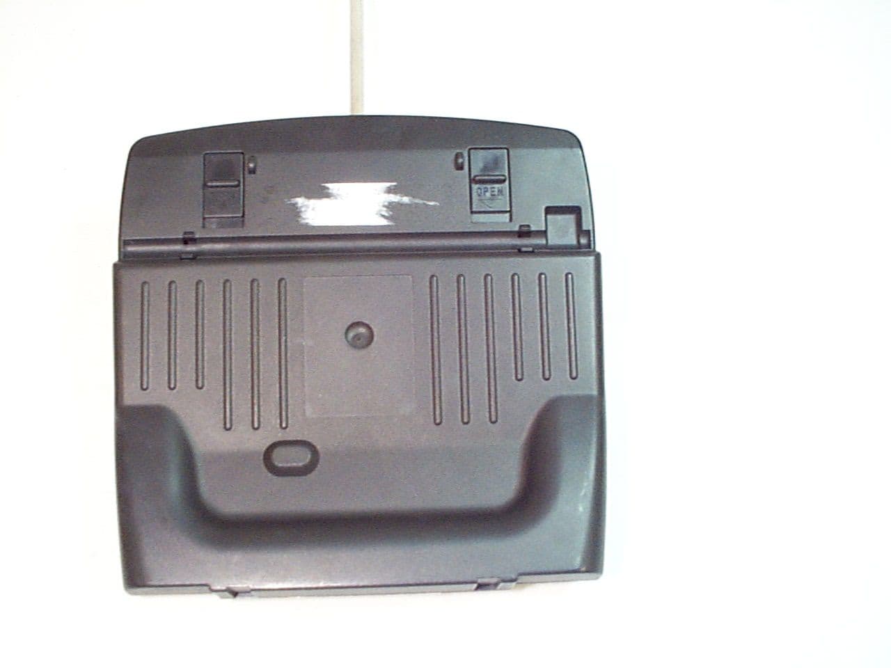
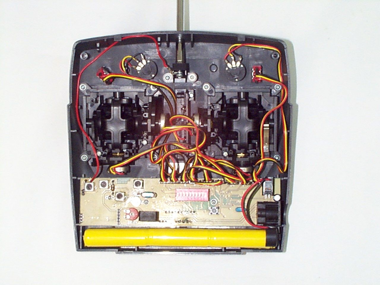
Click to zoom
Application Details
- Equipment Class
- TNB - Licensed Non-Broadcast Station Transmitter
- Date of Grant
- Dec 14, 1999
- Application Purpose
- Original Equipment
- Date of Application
- Sep 16, 1999
- Equipment Note
- Remote Control Transmitter
- Frequency Range
- 72.01000000 - 72.99000000
- Company
- Multiplex USA
- Country
- United States
Documents & Files
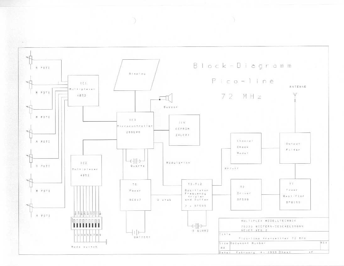
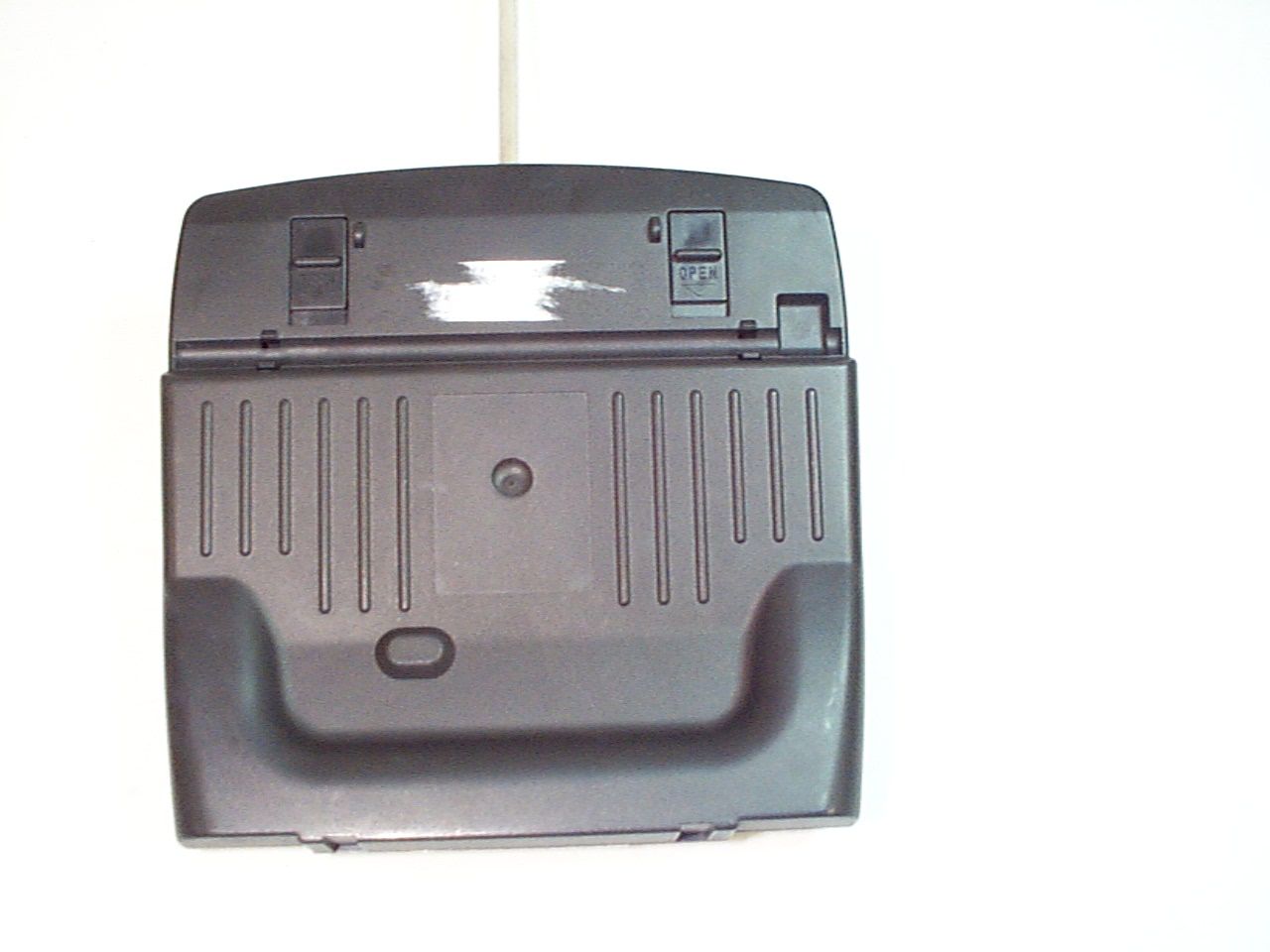
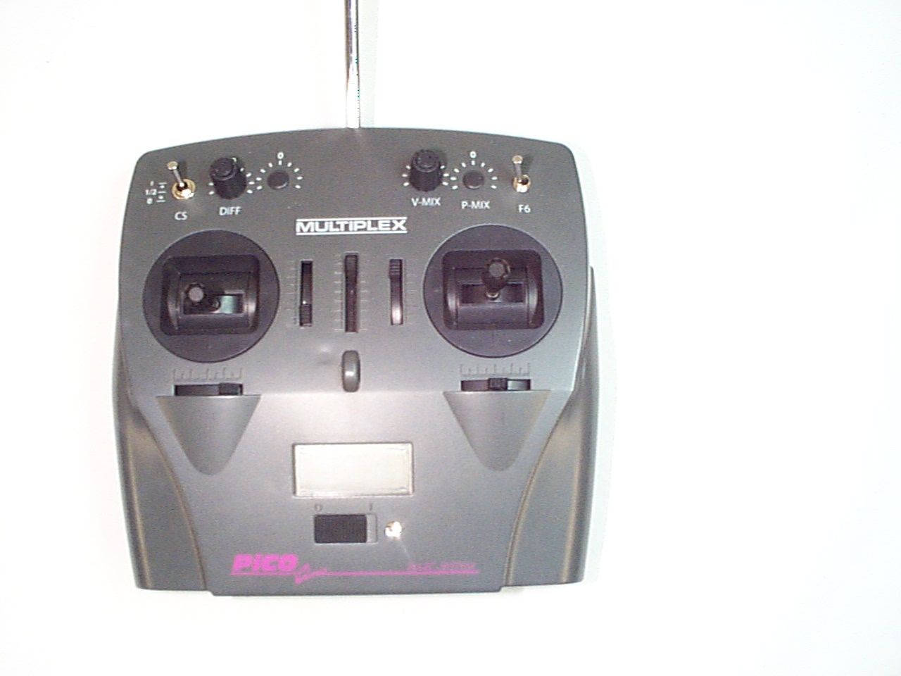
Document Text
Text extracted from the exhibit documents filed with the FCC. Open a document above to read the original.
Cover Letter(s)
September 20, 1999 Chief Authorizations Branch Federal Communications Commission 7435 Oakland Mills Road Columbia, MD 21046 Re:FCC ID:NT9PICOCOCKPIT; Confirmation #: EA95432 To Whom It May Concern: A application for Type Acceptance under Part 95 was electronically submitted for the above-referenced FCC ID and Confirmation Number on Friday, September 20, 1999. An incorrect product description was used (DSC Part 15). The correct description (Part 95) is “Family Radio Base Transmitter” with the code “FRB”. I have submitted a hand- typed 159 form to Pittsburgh with the correct fee code, EFT, and payment of $475.00. The unit is a R/C Transmitter for control of a model aircraft. Should you have any questions or concerns regarding these matters, please do not hesitate to contact me. Sincerely, Ann S. Miller Technical Report Write Enclosure WLL Project #: 5206X
ID Label/Location Info
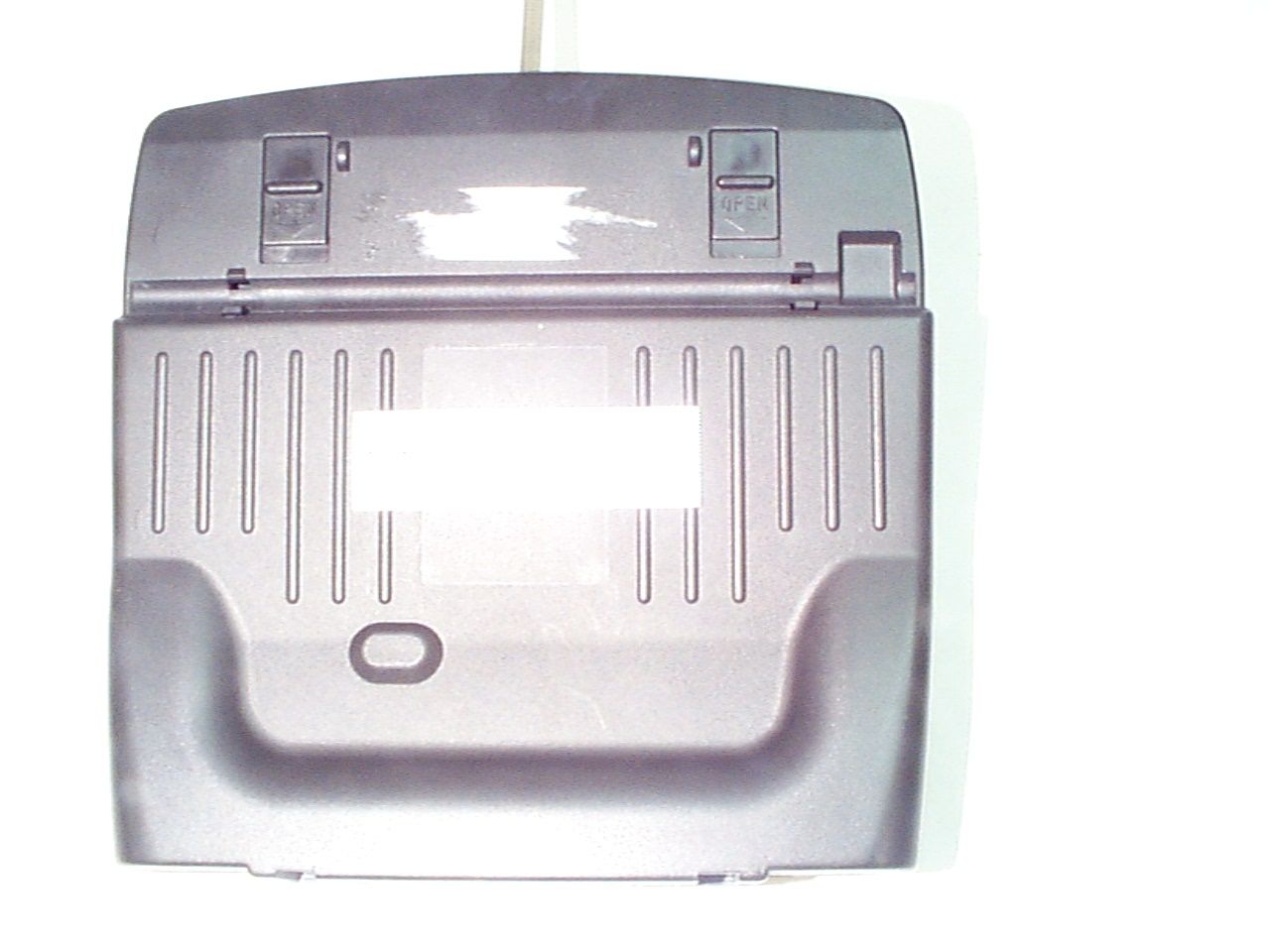
MULTIPLEX Model: PICO Line FCC ID: NT9PICOCOCKPIT
Test Report
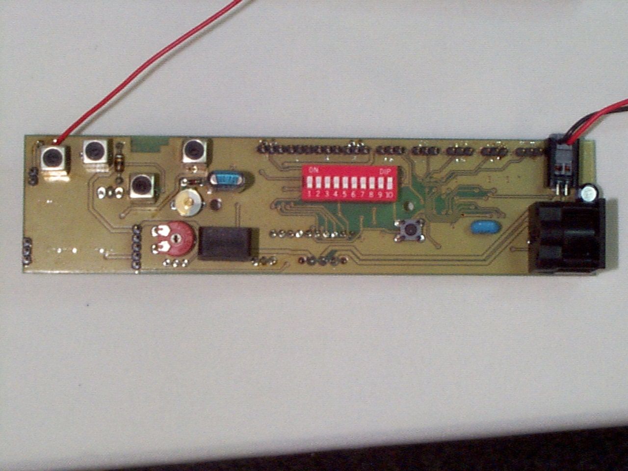
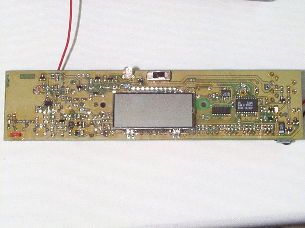
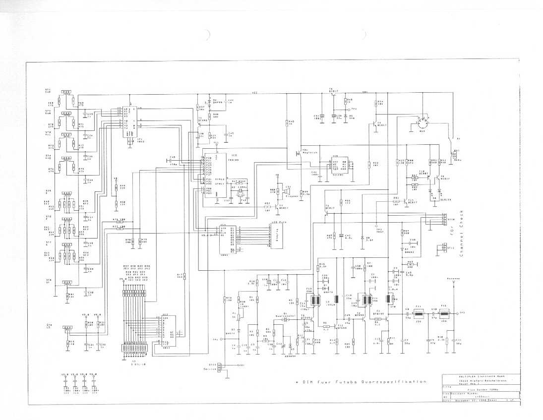
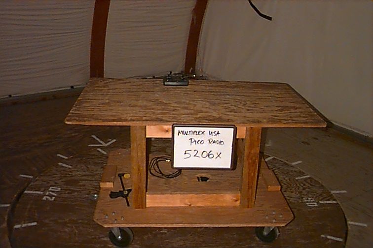
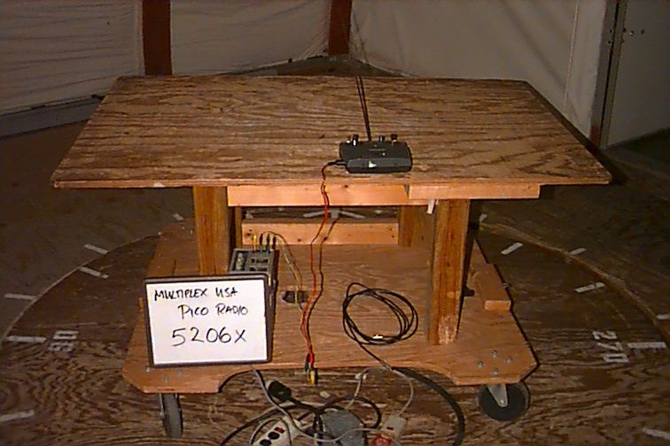
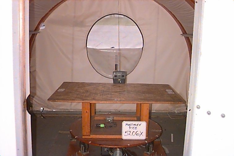
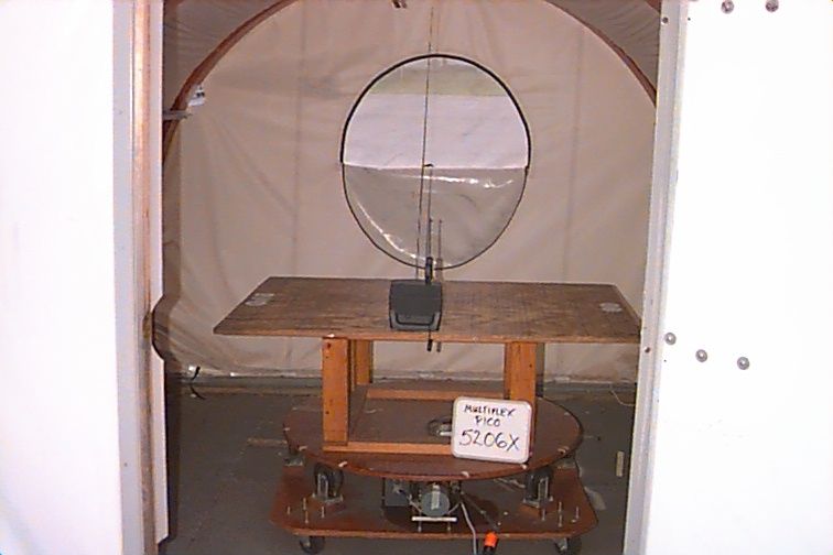
FCC CERTIFICATION TEST REPORT prepared for MULTIPLEX USA 14751 Calvert Street Van Nuys, CA 91411 FCC ID: NT9PICOCOCKPIT September 14, 1999 WLL PROJECT #: 5206X This report shall not be reproduced, except in full, without the prior written consent of Washington Laboratories, Ltd. MULTIPLEX USA FCC ID: NT9PICOCOCKPIT WLL Project #: 5206X i TABLE OF CONTENTS Statement of Qualifications ________________________________________________ 1.0 INTRODUCTION................................................................................................................................................. 2 1.1 S UMMARY............................................................................................................................................................ 2 2.0 DESCRIPTION OF EQUIPMENT UNDER TEST (EUT) ............................................................................... 2 3.0 TEST CONFIGURATION................................................................................................................................... 2 3.1 RF O UTPUT POWER (FCC RULE PART 95.639) ................................................................................................... 3 3.2 A UTHORIZED BANDWIDTH (FCC RULE PART 95.633) ......................................................................................... 3 3.3 R ADIATED EMISSIONS TESTING (FCC RULE PART 95.635) .................................................................................. 3 3.3.1 Radiated Data Reduction and Reporting ..................................................................................................... 4 3.4 F REQUENCY STABILITY (FCC RULE PART 95.623) .............................................................................................. 7 TABLES Table 1.Radiated Emissions Data Table 2.Measurement Equipment Used APPENDICES Appendix A.Occupied Bandwidth Plot Appendix B.Statement of Measurement Uncertainty MULTIPLEX USA FCC ID: NT9PICOCOCKPIT WLL Project #: 5206X 1 MULTIPLEX USA FCC ID: NT9PICOCOCKPIT WLL Project #: 5206X 2 FCC CERTIFICATION REPORT for MULTIPLEX USA 1.0 Introduction This report has been prepared on behalf of MULTIPLEX USA in support of their application for FCC Certification under Part 95 of the FCC Rules and Regulations for an R/C transmitter. The Equipment Under Test was the PICO Radio model aircraft remote control transmitter. All measurements were performed at Washington Laboratories, Ltd. test center in Gaithersburg, MD. Site description and site attenuation data have been placed on file with the FCC's Sampling and Measurements Branch at the FCC laboratory in Columbia, MD. Washington Laboratories has been accepted by the FCC and approved by NIST NVLAP (NVLAP Lab Code 200066-0) as an independent FCC test laboratory. Measurements were made on the Equipment Under Test in accordance with FCC Rule Part 2 and Part 95, specifically the requirements stipulated in Part 95 Subpart E – Technical Regulations All results reported herein relate only to the item tested. This report shall not be used to claim product endorsement by NVLAP or any agency of the US Government. The measurement uncertainty of the data contained herein is ±2.3 dB. Refer to Appendix C for Statement of Measurement Uncertainty. 1.1 Summary The MULTIPLEX USA PICO Radio complies with the technical requirements of Part 95 of the FCC Rules and Regulations. 2.0 Description of Equipment Under Test (EUT) The MULTIPLEX USA PICO Radio is a model aircraft remote control transmitter. The EUT is hand-held battery powered and provides for the remote operation of model aircraft. The unit operates in the 72.01-72.99 MHz band reserved for this purpose and provides control for full aircraft flight. The R/C transmitter uses FM-PPM modulation with a frequency deviation of 1.5 kHz. 3.0 Test Configuration To complete the test configuration required by the FCC, the R/C Transmitter was tested with the transmitter being set to continuously transmit. For emissions testing the EUT antenna was placed both horizontally and vertically. A power supply was used to power the EUT and to avoid battery drain. MULTIPLEX USA FCC ID: NT9PICOCOCKPIT WLL Project #: 5206X 3 3.1 RF Output Power (FCC Rule Part 95.639) The EUT was placed on a 0.8m table with the antenna fully extended. A power charging cord was connected to keep the unit at full charge power, however, the unit only runs off batteries. The output from the transmitter was connected to a 20 dB attenuator and then to the input of an HP 8564E RF Spectrum Analyzer. The analyzer offset was adjusted to compensate for the 10 dB attenuator. The RF output power across a 50 ohm load termination was measured directly by the analyzer. RESULTS: The measured RF output power was 20 dBm, or 0.1 W. LIMIT:For 72-76 MHz operation: 0.75 W 3.2 Authorized Bandwidth (FCC Rule Part 95.633) The authorized bandwidth was measured using the same setup that was used for the RF power measurements test except for the spectrum analyzer resolution bandwidth was set to 1000 Hz. Results of the testing are displayed in Appendix A of this report. RESULTS:7.05 kHz LIMIT:8 kHz 3.3 Radiated Emissions Testing (FCC Rule Part 95.635) The EUT was placed on an 80 cm high, 1 X 1.5 meters non-conductive motorized turntable for radiated testing on a 3 meter open field test site. The emissions from the EUT were measured continuously at every azimuth by rotating the turntable. Broadband antennas were mounted on an antenna mast to determine the height of maximum emissions. The height of the antenna was varied between 1 and 4 meters. Horizontal and vertical field components were measured. The EUT was setup in a fixed in an upright position with the antenna vertical and laying flat and with the antenna horizontal. The batteries were fully charged during testing. Emissions were measured in both vertical and horizontal polarization. The output from the antenna was connected, via a preamplifier, to the input of the spectrum analyzer. The d…
Text truncated - open the document above for the full version.
Contact Information
Applicant
Tony Ohm(Service Manager)
858-748-8440Fax: 858-859-2618
Technical Contact
Washigton Laboratories, Ltd.Greg M Snyder
[email protected]301/417-0220
7560 Lindbergh Drive · Gaithersburg, Maryland · United States
Non-Technical Contact
Washington Laboratories, Ltd.Ann S Miller
[email protected]301/417-0220
Test Firm
Washington Laboratories, Ltd.Michael Violette
Technical Specifications
| # | Rule Parts | Frequency Range | Power Output | Emission | Tolerance |
|---|---|---|---|---|---|
| 1 | 95 | 72.01 MHz - 72.99 MHz | 100.00 mW | 6K00A1D | 0.0020000000 % |
Other Applications from Multiplex USA

NT9-PROFI-CAR
Jun 28, 2000Model Aircraft Radio Control Transmitter
Equipment Class
TNB - Licensed Non-Broadcast Station Transmitter
NT9PROFIROYAL
Mar 05, 2000Model Aircraft Radio Control Transmitter
Equipment Class
TNB - Licensed Non-Broadcast Station Transmitter