NTRNSA1800AMPS Band Cellular Modem
Niigata Seimitsu Co Ltd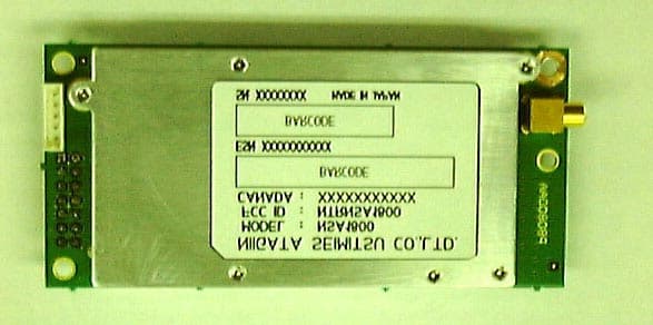
Click to zoom
Application Details
- Equipment Class
- TNB - Licensed Non-Broadcast Station Transmitter
- Date of Grant
- May 02, 2001
- Application Purpose
- Original Equipment
- Date of Application
- May 02, 2001
- Equipment Note
- AMPS Band Cellular Modem
- Frequency Range
- 824.04000000 - 848.97000000
- Company
- Niigata Seimitsu Co Ltd
- Country
- Japan
Documents & Files
Document Text
Text extracted from the exhibit documents filed with the FCC. Open a document above to read the original.
Users Manual
Niigata Seimitsu LTD, Co. NSA-1800 © USER MANUAL Revision 1.0 NSA-1800 © © 2001 Copyright Fluent Data Systems LLC all rights Reserved Page 2 FCC/IC Compliance Statement This device complies with Part 15 of FCC Rules and with RSS-210 of Industry and Science Canada. Operation is subject to the following conditions: (1) This device may not cause interference, and (2) This device must accept any interference, including interference that may cause undesired operation of this device. Thank you for trusting your RF communication needs to Niigata Seimitsu LTD, Co. and our NSA- 1800 family of products. You have selected a high performance, small footprint, AMPS RF device with advanced OEM development features. We encourage you to review this user guide to help familiarize yourself with the operation of the NSA-1800. © 2001 Copyright Fluent Data Systems LLC all rights Reserved Page 3 Index SAFETY INFORMATION..............................................4 WARNING - FCC RF EXPOSURE REQUIREMENTS...4 NSA-1800 SAFETY TIPS...............................................6 ELECTRONIC DEVICES...............................................7 GENERAL DESCRIPTION............................................9 NSA-1800 MODELS.....................................................10 TECHNICAL SPECIFICATIONS.................................11 Absolute Maximum Ratings........................................11 General ( Ta=-30ºC to +60ºC )..................................11 Receiver (Ta=-30ºC to +60ºC, VCC=+4.8VDC)...........12 Transmitter (Ta=-30ºC to +60ºC, VCC=+4.8VDC)......12 INTERFACE CONNECTOR (J1)..................................13 ANTENNA CONNECTOR (J2)....................................14 AUDIO INTERFACE CONNECTOR (J3).....................15 MECHANICAL LAYOUT............................................16 SUPPORT.....................................................................17 © 2001 Copyright Fluent Data Systems LLC all rights Reserved Page 4 SAFETY INFORMATION WARNING - FCC RF EXPOSURE REQUIREMENTS EXPOSURE TO RADIO FREQUENCY SIGNALS Your wireless device is a low power radio transmitter and receiver. When installed the device receives and transmits RF signals. In August 1996 the Federal Communications Commission (FCC) adopted RF exposure guidelines with safety levels for mobile wireless devices. Those guidelines are consistent with the safety standards previously set by both U.S. and international standards bodies: American National Standards Institute – ANSI C95.1 (1992) National Council on Radiation Protection and Measurements – NCRP Report 86 (1986) International Commission on Non-Ionizing Radiation Protection – ICNIRP (1996) Those standards were based on comprehensive and periodic evaluations of the relevant scientific literature. For example, over 120 scientists, engineers, and physicians from universities, government’s health agencies, and industry reviewed the available body of research to develop the ANSI Standard (C95.1) © 2001 Copyright Fluent Data Systems LLC all rights Reserved Page 5 WARNING! To comply with FCC RF Exposure compliance requirement, the following antenna installattion and device operating configurations must be satisfied: • The antenna, p/n EX00-0336-00, used for this transmitter must be installed to provide a separation distance of at least 20 cm from all persons and must not be co-located or operating in conjunction with any other antenna or transmitter. • Vehicle antenna mounting: Antenna must be mounted externally to the vehicle. This mounting could be anywhere excepted windows. • Fixed application – Home or Business: o The antenna, used with this device, must be fixed-mounted on indoor or outdoor permanent structures providing a separation distance of at least 20 cm from all persons during normal operation. © 2001 Copyright Fluent Data Systems LLC all rights Reserved Page 6 NSA-1800 SAFETY TIPS Your NSA-1800 gives you the ability to communicate by data-almost anywhere, anytime. But an important responsibility accompanies the benefits of wireless devices, one that every user/installer must uphold. When installing this device please keep the following items in mind: 1. Get to know your NSA-1800 and its features such as voltage, ground, mounting and data connections. 2. The antenna system is 50 ohms. Please use the least amount of distance when installing. We recommend the use of Niigata Seimitsu LTD, Co. antennas and accessories. Please ask your representative about optional antennas and cables. 3. Position your NSA-1800 within RF coverage. Cellular coverage may be poor in basements or tunnels. 4. Install in well-ventilated areas. Excessive heat will damage the NSA-1800 or hinder the optimal operation. © 2001 Copyright Fluent Data Systems LLC all rights Reserved Page 7 ELECTRONIC DEVICES Most electronic equipment is shielded from RF signals. However, certain electronic equipment may not be shielded against the RF signals from your NSA- 1800. Pacemakers The Health Industry Manufacturers Association recommends that a minimum separation of six (6") inches be maintained between a NSA-1800 and a pacemaker to avoid potential interference with the pacemaker. These recommendations are consistent with the independent research by and recommendations of Wireless Technology Research. Other Medical Devices If you install this device near a personal medical device, consult the manufacturer of your device to determine if they are adequately shielded from external RF energy. Vehicles RF signals may affect improperly installed or inadequately shielded electronic systems in motor vehicles. Check with the manufacturer or its representative regarding the vehicle. You should also consult the manufacturer of any equipment that has been added to the vehicle. © 2001 Copyright Fluent Data Systems LLC all rights Reserved Page 8 AIRCRAFT FCC regulations prohibit using this device on aircraft. BLASTING AREAS To avoid interfering with blasting operating, the NSA- 1800 must be disabled or in the “OFF”…
Text truncated - open the document above for the full version.
Attestation Statements
American Telecommunications Certification Body Inc. 6731 Whittier Ave, McLean, VA 22101 March 28, 2001 RE: FCC ID: NTRNSA1800 I have a few problems with this application that much be addressed. You are cautioned that transmitters, which do not meet the RF power Categorical Exclusion rules of 1.1307, are not eligible for TCB approval. For equipment in this frequency range this is defined as 1.5 Watts conducted, and 1.5 Watts EIRP. All others must be filed with the FCC. 1.) The Product Description refers to this as a module. All licensed modular approvals are currently excluded from the scope of TCB authorization. Please explain. This is not an application for a modular approval. We have corrected the Product Description and provided a new document.. 2.) A simpler RF exposure equation exists in OET Bulletin 65. See Section 4: Prediction Methods ,; Equations for Predicting RF Fields. Equation 4) is most commonly used by simply re-arranged to solve for R. Be sure to enter your EIRP in milliwatts. S would represent the limit. Noted. Thank you 3.) Power output on 731 does not match RF exposure evaluation. The 731 Form has been corrected and is provided. 4.) The file for External Photos would not open. Please upload again. Submitting new file. Please let me know if you still have problems 5.) For clarity, calculated method in 3.1 in the test report should not even be mentioned. Calculated method in 3.1 has been removed from the report. Please see the Revised Report Body 6.) Radiated ERP using the substitution method is usually much more accurate than +/- 1.5 dB. Variations of 40% are a bit high. Noted. Thank you 7.) Occupied Bandwidth looks much better. Noted. Thank you 8.) Tx Radiated and Conducted spurs well presented. Noted. Thank you 9.) Graphs in Section 8.2.2 and 11.2 will never print properly on B&W printers. If possible please remove gray background. Background was changed per your request. Please see the Revised Report Body 10.) Please provide a listing of instantaneous deviations of all signals listed in 22.915(b). Please see section 11.2 of the revised report body. 11.) Please provide explanation of ESN encryption under 22.919. Attestation is provided. Please see Attestation Letter provided in cover letter. l Page 2 April 10, 2001 12.) Please provide attestation to 22.933. Attestation is provided with number 11 of this document. Please see Attestation Letter provided in cover letter. 13.) Will only 2.15 dBi antennas be used with this device? Please provide listing of all applicable antennas. Please see the files uploaded in RF Exposure file on the ATCB Web Site 14.) Confidentiality letter is not on Applicant letterhead. Rhein Tech Laboratories, Inc. is acting as agent for the applicant and can send the letter on their behalf. In section 0.459 of the FCC Rules and Regulations it is not stated that a letter head must be used for a confidential letter. It does however list other requirements. 15.) Please identify where in the application I can find the DC I and E to the finals per 2.1033(c)(8) Please see Section 13 of the revised report body. 16.) There are no installation instructions to assure this equipment will be properly installed in compliance with the fixed or mobile transmitter distance rules. Revised manual is provided. Please see Revised Manual. 17.) The contact information for “NTR” is incorrect. Please inform Bette Taube at FCC. Noted will take care of this matter. 18.) What is the relationship between Niigata and Fluent? Would it not be best if Fluent be the Applicant? Fluent is acting as agent for Niigata. I have already made the suggestion but they do not want to do this for this application but probably will for future applications William H. Graff Examining Engineer President and Director of Engineering The items indicated above must be submitted before processing can continue on the above referenced application. Failure to provide the requested information within 30 days of the original e-mail date may result in application dismissal pursuant to Section 2.917(c). Correspondence should be considered part of the permanent submission and may be viewed from the Internet after a Grant of Equipment Authorization is issued. Please do not reply to this correspondence using the email reply button. In order for your response to be processed expeditiously, you must attach your answers to email correspondence. Reply to the examiner at the email address shown below. Also, please note that partial responses increase processing time and should not be submitted. Any questions about the content of this correspondence should be directed to the e-mail address listed below the name of the sender.
Cover Letter(s)
Engineering and Testing for EMC and Safety Compliance 360 Herndon Parkway, Suite 1400 Herndon, VA 20170 Phone: 703-689-0368; Fax: 703-689-2056; Metro: 703-471-6441 March 22, 2001 Federal Communications Commission 7435 Oakland Mills Road Columbia, MD 21046 To Whom It May Concern: The following information is to be held confidential pursuant of 47 CFR Part 0 §0.457 and Section 552(b)(4) of the Freedom of Information Act, because the information provided contains trade secrets and proprietary. If made public, the information might be used to the disadvantage of the applicant in the market place. • Schematics • Product Description • Block Diagram Best Regards, Melissa Fleming. [email protected] Rhein Tech Laboratories, Inc.
Cover Letter(s)
American Telecommunications Certification Body Inc. 6731 Whittier Ave, McLean, VA 22101 March 28, 2001 RE: FCC ID: NTRNSA1800 I have a few problems with this application that much be addressed. You are cautioned that transmitters, which do not meet the RF power Categorical Exclusion rules of 1.1307, are not eligible for TCB approval. For equipment in this frequency range this is defined as 1.5 Watts conducted, and 1.5 Watts EIRP. All others must be filed with the FCC. 1.) The Product Description refers to this as a module. All licensed modular approvals are currently excluded from the scope of TCB authorization. Please explain. 2.) A simpler RF exposure equation exists in OET Bulletin 65. See Section 4: Prediction Methods ,; Equations for Predicting RF Fields. Equation 4) is most commonly used by simply re-arranged to solve for R. Be sure to enter your EIRP in milliwatts. S would represent the limit. 3.) Power output on 731 does not match RF exposure evaluation. 4.) The file for External Photos would not open. Please upload again. 5.) For clarity, calculated method in 3.1 in the test report should not even be mentioned. 6.) Radiated ERP using the substitution method is usually much more accurate than +/- 1.5 dB. Variations of 40% are a bit high. 7.) Occupied Bandwidth looks much better. 8.) Tx Radiated and Conducted spurs well presented. 9.) Graphs in Section 8.2.2 and 11.2 will never print properly on B&W printers. If possible please remove gray background. 10.) Please provide a listing of instantaneous deviations of all signals listed in 22.915(b). 11.) Please provide explanation of ESN encryption under 22.919. 12.) Please provide attestation to 22.933. 13.) Will only 2.15 dBi antennas be used with this device? Please provide listing of all applicable antennas. 14.) Confidentiality letter is not on Applicant letterhead. 15.) Please identify where in the application I can find the DC I and E to the finals per 2.1033(c)(8) 16.) There are no installation instructions to assure this equipment will be properly installed in compliance with the fixed or mobile transmitter distance rules. 17.) The contact information for “NTR” is incorrect. Please inform Bette Taube at FCC. 18.) What is the relationship between Niigata and Fluent? Would it not be best if Fluent be the Applicant? William H. Graff Examining Engineer President and Director of Engineering The items indicated above must be submitted before processing can continue on the above referenced application. Failure to provide the requested information within 30 days of the original e-mail date may result in application dismissal pursuant to Section 2.917(c). Correspondence should be considered part of the permanent submission and may be viewed from the Internet after a Grant of Equipment Authorization is issued. Please do not reply to this correspondence using the email reply button. In order for your response to be processed expeditiously, you must attach your answers to email correspondence. Reply to the examiner at the email address shown below. Also, please note that partial responses increase processing time and should not be submitted. Any questions about the content of this correspondence should be directed to the e-mail address listed below the name of the sender.
Cover Letter(s)
American Telecommunications Certification Body Inc. 6731 Whittier Ave, McLean, VA 22101 April 16, 2001 RE: FCC ID: NTRNSA1800 In order for this product to qualify for TCB approval, two conditions must still be met. First, I must be satisfied that this is equipment will NOT be used in a modular configuration [licensed modular approvals are currently excluded from TCB approval]. Second, I must be satisfied the conducted RF output and radiated ERP will not exceed 1.5W. The following questions address these two points. 1.) The parts list includes a low profile “Disc” antenna with 3dBi gain. This is in excess of the 0dBd for all antennas claimed in the RF exposure report, and puts the total ERP in excess of 1.5W. Please explain. 2.) This equipment claims to be compliant with IS-19B. This specification has very wide tolerances for conduced power output. How does the manufacture intend to insure compliance with the 1.5W-conducted limit? Please provide as a signed attestation. 3.) It appears that this device can easily be viewed as a modular application, and therefore excluded from TCB approval. Please provide examples for its end use. Also, please provide Applicant attestation that this device will not be used as a module. William H. Graff Examining Engineer President and Director of Engineering mailto:[email protected] The items indicated above must be submitted before processing can continue on the above referenced application. Failure to provide the requested information may result in application termination. Correspondence should be considered part of the permanent submission and may be viewed from the Internet after a Grant of Equipment Authorization is issued. Please do not respond to this correspondence using the email reply button. In order for your response to be processed expeditiously, you must submit your documents through the AmericanTCB.com website. Also, please note that partial responses increase processing time and should not be submitted. Any questions about the content of this correspondence should be directed to the sender.
External Photos
360 Herndon Parkway Suite 1400 Herndon, VA 20170 http://www.rheintech.com FCC And Canadian Certification Report Page 52 21 EXTERNAL PHOTOGRAPHS Model No.: NSA 1800 General Top View Model No.: NSA 1800 General Bottom View 360 Herndon Parkway Suite 1400 Herndon, VA 20170 http://www.rheintech.com FCC And Canadian Certification Report Page 53 Model No.: NSA 1800 Exterior Top View Model No.: NSA 1800 Exterior Bottom View
ID Label/Location Info
360 Herndon Parkway Suite 1400 Herndon, VA 20170 http://www.rheintech.com FCC And Canadian Certification Report Page 43 14 LABEL INFORMATION
Internal Photos
360 Herndon Parkway Suite 1400 Herndon, VA 20170 http://www.rheintech.com FCC And Canadian Certification Report Page 50 20.1 INTERNAL PHOTOGRAPHS Model No.: NSA 1800 Inside Top View - PCB 360 Herndon Parkway Suite 1400 Herndon, VA 20170 http://www.rheintech.com FCC And Canadian Certification Report Page 51 Model No.: NSA 1800 Inside Bottom View - PCB
Parts List/Tune Up Info
360 Herndon Parkway Suite 1400 Herndon, VA 20170 http://www.rheintech.com FCC And Canadian Certification Report Page 48 19 PARTS LIST 2SA1037AK / 2SA1576A / 2SA1774 / Transistors 2SA1774H / 2SA933AS General Purpose Transistor ( − 50V, − 0.15A) 2SA1037AK / 2SA1576A / 2SA1774 / 2SA1774H / 2SA933AS ! Features 1) Excellent h FE linearity. 2) Complements the 2SC2412K / 2SC4081 / 2SC4617 / 2SC4617H / 2SC1740S. ! Structure Epitaxial planar type. PNP silicon transistor ! External dimensions (Units : mm) 2SA1037AK Abbreviated symbol : F ∗ Abbreviated symbol : F ∗ ∗ Denotes h FE Abbreviated symbol : F ∗ Abbreviated symbol : F ∗ ROHM : SMT3 EIAJ : SC-59 (3) Collector (1) Emitter (2) Base Each lead has same dimensions 0.8 0.15 0to0.1 0.3to0.6 1.1 ( 2 ) ( 1 ) 2.8 1.6 0.4 ( 3 ) 2.9 1.9 0.95 0.95 2SA1774 ROHM : EMT3 EIAJ : SC-75A (3) Collecto (1) Emitter (2) Base 0.7 0.15 0.1Min. 0.55 0to0.1 0.2 1.6 1.61.0 0.3 0.8 ( 2 ) 0.5 0.5 ( 3 ) 0.2 ( 1 ) 2SA1576A ROHM : UMT3 EIAJ : SC-70 (3) Collector (1) Emitter (2) Base Each lead has same dimensions 1.25 2.1 0.3 0.15 0to0.1 0.1to0.4 ( 3 ) 0.9 0.7 0.2 0.65 ( 2 ) 2.0 1.3 ( 1 ) 0.65 2SA933AS ROHM : SPT EIAJ : SC-72 0.45 2.5 ( 1 ) ( 2 ) ( 3 ) (3) Base (1) Emitter (2) Collector ( 15Min. ) 5 3 3Min. Taping specifications 0.45 0.5 42 2SA1774H ROHM : EMT3 Flat lead EIAJ : SC-89 (1) Emitter (3) Collector (2) Base 0.12 0to0.1 0.27 ( 3 ) 0.7 1.0 0.5 0.5 1.6 1.6 0.85 ( 1 ) ( 2 ) 2SA1037AK / 2SA1576A / 2SA1774 / Transistors 2SA1774H / 2SA933AS ! Absolute maximum ratings (Ta=25 ° C) Collector-base voltage Collector-emitter voltage Emitter-base voltage Collector current Collector power dissipation Junction temperature Storage temperature Parameter V CBO VCEO VEBO IC PC Tj Tstg −60V V V A (DC) ̊C ̊C −50 −6 −0.15 W 0.2 0.15 0.3 2SA1037AK, 2SA1576A 2SA1774H, 2SA1774 2SA933AS 150 − 55~+150 SymbolLimitsUnit ! Electrical characteristics (Ta=25 ° C) Collector-base breakdown voltage Collector-emitter breakdown voltage Emitter-base breakdown voltage Collector cutoff current Emitter cutoff current DC current transfer ratio Collector-emitter saturation voltage Transition frequency Output capacitance ParameterSymbol BV CBO BVCEO BVEBO ICBO IEBO hFE VCE(sat) fT Cob Min. −60 −50 −6 - - 120 - - - - - - - - - - 140 4.0 - - - −0.1 −0.1 560 −0.5 - 5.0 VI C=−50μA I C=−1μA I E=−50μA V CB=−60V V EB=−6V V CE=−6V, IC=−1mA I C/IB=−50mA/−5mA V CE=−12V, IE=2mA, f=30MHz V CB=−12V, IE=0A, f=1MHz V V μA μA - V MHz pF Typ.Max.UnitConditions ! Packaging specifications and h FE Package Code Taping Basic ordering unit (pieces) QRS h FE 2SA1037AK T146 3000 - -QRS 2SA1576A T106 3000 - - TL 3000 - - -QRS 2SA1774 - - -QRS 2SA1774H -- T2L 8000 - - - - -QRS 2SA933AS --- TP 5000 Type h FE values are classified as follows: ItemQRS h FE120~270180~390270~560 2SA1037AK / 2SA1576A / 2SA1774 / Transistors 2SA1774H / 2SA933AS ! Electrical characteristic curves Fig.1 Grounded emitter propagation characteristics −0.2 COLLECTOR CURRENT : Ic ( mA) −50 −20 −10 −5 −2 −1 −0.5 −0.2 −0.1 −0.4−0.6−0.8−1.0−1.2−1.4−1.6 VCE=−6V BASE TO EMITTER VOLTAGE : VBE (V) Ta=100 ̊C 25 ̊C −40 ̊C Fig.2 Grounded emitter output characteristics (I) −0.4 −4 −8 −1.20 −2 −6 −10 −0.8−1.6−2.0 −3.5μA −7.0 −10.5 −14.0 −17.5 −21.0 −24.5 −28.0 −31.5 I B=0 Ta=25 ̊C −35.0 COLLECTOR CURRENT : I C ( mA) COLLECTOR TO MITTER VOLTAGE : VCE (V) Fig.3 Grounded emitter output characteristics (II) −40 −80 −5−3−4−2−1 −20 −60 −100 0 IB=0 Ta=25 ̊C COLLECTOR CURRENT : I C ( mA ) COLLECTOR TO EMITTER VOLTAGE : VCE (V) −50μA −100 −150 −200 −250 −500 −450 −400 −350 −300 Fig.4 DC current gain vs. collector current (I) 500 200 100 50 −0.2−0.5−1−2−5−10−20−50−100 DC CURRENT GAIN : h FE Ta=25 ̊C VCE=−5V −3V −1V COLLECTOR CURRENT : IC (mA) Fig.5 DC current gain vs. collector current (II) 500 200 100 50 −0.2−0.5−1−2−5−10−20−50−100 DC CURRENT GAIN : h FE COLLECTOR CURRENT : IC (mA) VCE=−6V Ta=100 ̊C −40 ̊C 25 ̊C Fig.6 Collector-emitter saturation voltage vs. collector current (I) −0.1 −0.2−0.5−1−2−5−10−20−50−100 −1 −0.5 −0.2 −0.05 Ta=25 ̊C COLLECTOR CURRENT : IC (mA) IC/IB=50 20 10 COLLECTOR SATURATION VOLTAGE : V CE(sat) ( V) Fig.7 Collector-emitter saturation voltage vs. collector current (II) −0.1 −0.2−0.5−1−2−5−10−20−50−100 −1 −0.5 −0.2 −0.05 COLLECTOR CURRENT : IC (mA) lC/lB=10 Ta=100 ̊C 25 ̊C −40 ̊C COLLECTOR SATURATION VOLTAGE : V CE(sat) ( V) Fig.8 Gain bandwidth product vs. emitter current 501000.520 50 100 200 500 1000 12 510 EMITTER CURRENT : I E (mA) TRANSITION FREQUENCY : f T ( MHz) Ta=25 ̊C VCE=−12V Fig.9 Collector output capacitance vs. collector-base voltage Emitter inputcapacitance vs. emitter-base voltage COLLECTOR TO BASE VOLTAGE : VCB (V) EMITTER TO BASE VOLTAGE : V EB (V) COLLECTOR OUTPUT CAPACITANCE : Cob ( pF) EMITTER INPUT CAPACITANCE : Cib ( pF) −0.5−20 2 5 10 −1−2−5−10 20 Cib Cob Ta=25 ̊C f=1MHz IE=0A IC=0A (96-134-B92) FExternal dimensions (Units: mm) 227 Transistors Low Frequency Transistor (*32V, *0.8A) 2SB1197K FFeatures 1) Low V CE(sat). V CE(sat) x *0.5V (I c/IB = *0.5A /*50mA) 2) I C = *0.8A. 3) Complements the 2SD1781K. FStructure Epitaxial planar type PNP silicon transistor FAbsolute maximum ratings (Ta = 25_C) FElectrical characteristics (Ta = 25_C) 228 Transistors2SB1197K FPackaging specifications and hFE hFE values are classified as follows : FElectrical characteristic curves (96-100-B208) (96-181-D208) 291 2SA1797 / 2SB1443 Transistors 2SC4672 © 1995 DATA SHEET SILICON TRANSISTOR The 2SC5289 is ideal for the final stage amplifier in 1.9G Hz-band digital cordless phones (DECT, PHS, etc.). FEATURES •P–1 = 27 dBm TYP. @f = 1.9 GHz, V CC = 3.6 V, ICq = 1 mA (Class AB), Duty = 1/8 • 4-Pin Mini Mold Package EIAJ: SC-61 ORDERING INFORMATION Part NumberQuantityPacking Style 2SC5289-T13 Kpcs/Reel Embossed tape 8 mm wide. Pin 3 (Base), Pin 4 (Emitter) face to perforation side of the tape. RemarkIf you require an evaluation sample, please contact an NEC Sales Representative. (Unit sample quantity is 50 pcs.) ABSOLUTE MAXIMUM RATINGS (TA = 25 °C) ParameterSy…
Text truncated - open the document above for the full version.
Test Report
Engineering and Testing for EMC and Safety Compliance 360 Herndon Parkway, Suite 1400 Herndon, VA 20170 Phone: 703-689-0368; Fax: 703-689-2056; Metro: 703-471-6441 CERTIFICATION REPORT Niigata Seimitsu Co., Ltd Shiba Daimon, 116 Bldg 8F, 16-3 1-Chome Shiba Daimon, Minato-Ku, Tokyo 105-0012 Japan MODEL: NSA1800 FCC ID: NTRNSA1800 March 6, 2001 STANDARDS REFERENCED FOR THIS REPORT PART 2: 1999 FREQUENCY ALLOCATIONS AND RADIO TREATY MATTERS; GENERAL RULES AND REGULATIONS PART 22: 1998 PUBLIC MOBILES SERVICES ANSI C63.4-1992 STANDARD FORMAT MEASUREMENT/TECHNICAL REPORT PERSONAL COMPUTER AND PERIPHERALS ANSI/TIA/EIA603- 1992 LAND MOBILE FM OR PM COMMUNICATIONS EQUIPMENT MEASUREMENT AND PERFORMANCE STANDARDS ANSI/TIA/EIA 603-1-1998 ADDENDUM TO ANSI/TIA/EIA 603-1992 RSS-118: Issue 2 Aug. 19, 1990, Supplement 1993-1 June 12, 1993, Amendment Issue 2 Aug. 24, 1996, Addendum Sept. 1, 1990 LAND AND SUBSCRIBER STATIONS: VOICE, DATA AND TONE MODULATED, ANGLE MODULATION RADIOTELEPHONE TRANSMITTERS AND RECEIVERS OPERATING IN THE CELLULAR MOBILE BANDS 824-849 MHz AND 869-894 MHz FCC Rules Parts Frequency Range Output Power Conducted (W) Freq. Tolerance Emission Designator 22 824-849 MHz 1.4 2.5 ppm 40K0F1D 22 824-849 MHz 1.4 2.5 ppm 40K0F8W Canadian Frequency Range Output Power Conducted (W) Freq. Tolerance Emission Designator RSS-118 824-849 MHz 1.4 2.5 ppm 40K0F1D RSS-118 824-849 MHz 1.4 2.5 ppm 40K0F8W REPORT PREPARED BY: Test Engineer: Daniel Baltzell Administrative Writer: Melissa Fleming Document Number: 2001040 No part of this report may be reproduced without the full written approval of Rhein Tech Laboratories, Inc. 360 Herndon Parkway Suite 1400 Herndon, VA 20170 http://www.rheintech.com FCC And Canadian Certification Report Page 2 TABLE OF CONTENTS 1 GENERAL INFORMATION.................................................................................................................................4 1.1 TEST FACILITY...................................................................................................................................................... 4 1.2 RELATED SUBMITTAL(S)/GRANT(S) .................................................................................................................... 4 1.3 CONFORMANCE STATEMENT...............................................................................................................................5 1.4 TESTED SYSTEM DETAILS.................................................................................................................................... 6 1.5 CONFIGURATION OF TESTED SYSTEM................................................................................................................. 6 1.6 FIELD STRENGTH CALCULATION......................................................................................................................... 7 1.7 RADIATED MEASUREMENT.................................................................................................................................. 8 2 FCC RULES AND REGULATIONS PART 2 §2.1046 (A): RF POWER OUTPUT: CONDUCTED.......9 2.1 TEST PROCEDURE................................................................................................................................................. 9 2.2 TEST EQUIPMENT.................................................................................................................................................. 9 2.3 TEST DATA.........................................................................................................................................................10 3 PART 2.1046 (A) AND PART 22.913 RF POWER OUTPUT: RADIATED - ERP....................................11 3.1 TEST PROCEDURE...............................................................................................................................................11 3.2 TEST DATA.........................................................................................................................................................12 3.3 TEST EQUIPMENT................................................................................................................................................12 4 FCC RULES AND REGULATIONS PART 2 §2.1051: SPURIOUS EMISSIONS AT ANTENNA TERMINALS ..................................................................................................................................................................13 4.1 TEST PROCEDURE...............................................................................................................................................13 4.2 TEST DATA.........................................................................................................................................................13 4.3 TEST EQUIPMENT................................................................................................................................................14 5 FCC RULES AND REGULATIONS PART 2 §2.1053 (A): FIELD STRENGTH OF SPURIOUS RADIATION ...................................................................................................................................................................15 5.1 TEST PROCEDURE...............................................................................................................................................15 5.2 TEST DATA.........................................................................................................................................................15 5.3 TEST EQUIPMENT................................................................................................................................................16 6 FCC RULES AND REGULATIONS PART 2 §2.1049 (C) (1): OCCUPIED BANDWIDTH...................17 6.1 TEST PROCEDURE...............................................................................................................................................17 6.2 TEST DATA..........................…
Text truncated - open the document above for the full version.
Test Setup Photos
360 Herndon Parkway Suite 1400 Herndon, VA 20170 http://www.rheintech.com FCC And Canadian Certification Report Page 49 20 TEST CONFIGURATION PHOTOGRAPHS Radiated Front View Radiated Back View
Contact Information
Applicant
Hiroshi Miyagi
03 3437-3570Fax: 03 3437-5622
Technical Contact
Rhein Tech Laboratories, Inc.Bruno Clavier
[email protected]703 689 0368
360 Herndon arkway · Herndon, Virginia · United States
Test Firm
Rhein Tech Laboratories, Inc.Rick McMurray
Technical Specifications
| # | Rule Parts | Frequency Range | Power Output | Emission | Tolerance |
|---|---|---|---|---|---|
| 2 | 22H | 824.04 MHz - 848.97 MHz | 1.4 W | 40K0F1D | 2.5 ppm |
Other Applications from Niigata Seimitsu Co Ltd
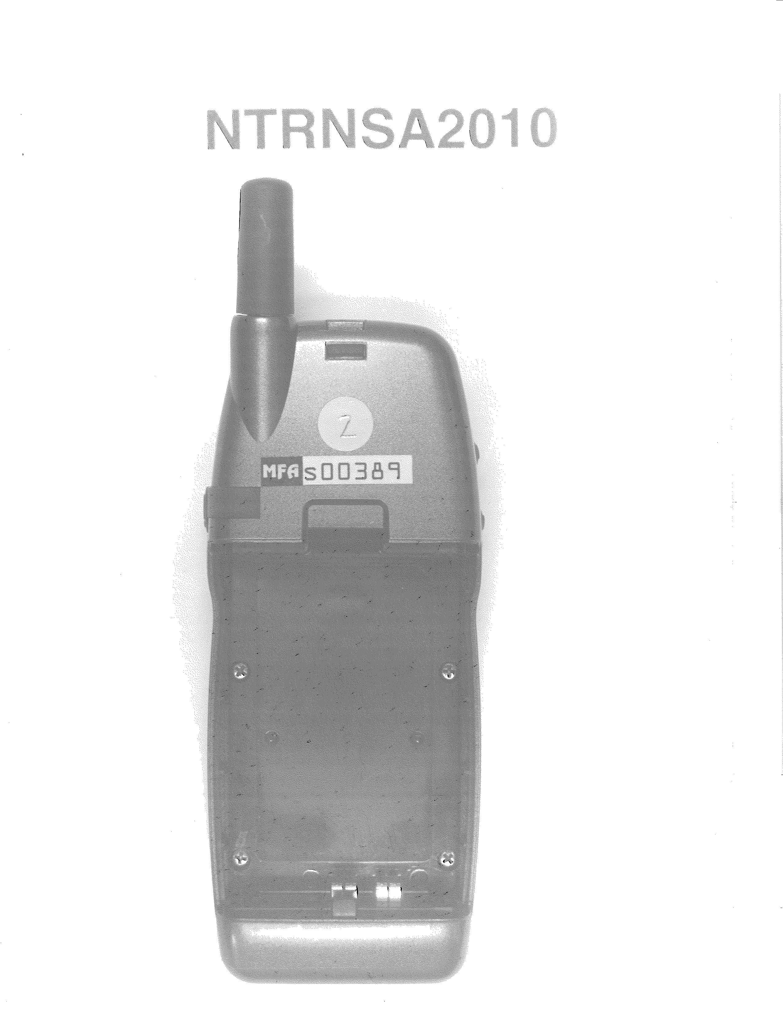
NTRNSA2010
Nov 14, 1999TNE - Licensed Non-Broadcast Transmitter Held to Ear
Equipment Class
TNE - Licensed Non-Broadcast Transmitter Held to EarNTRNST-100
Mar 22, 1998TNF - Licensed Non-Broadcast Transmitter Held to Face
Equipment Class
TNF - Licensed Non-Broadcast Transmitter Held to Face