NUX-ISP2401LAN transmitter
Clearwire Technologies Inc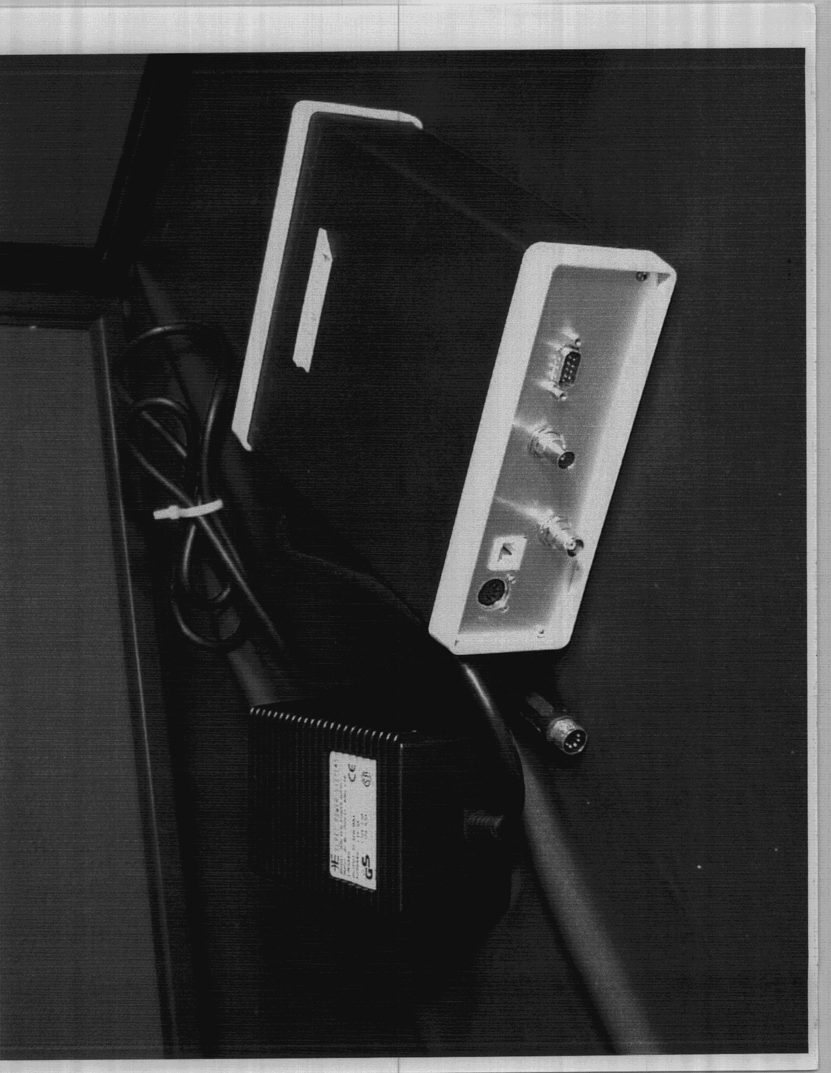
Click to zoom
Application Details
- Equipment Class
- DSS - Part 15 Spread Spectrum Transmitter
- Date of Grant
- Aug 18, 1998
- Application Purpose
- Original Equipment
- Date of Application
- Apr 13, 1998
- Equipment Note
- LAN transmitter
- Frequency Range
- 2408.62000000 - 2464.88000000
- Company
- Clearwire Technologies Inc
- Country
- United States
Documents & Files
Document Text
Text extracted from the exhibit documents filed with the FCC. Open a document above to read the original.
Attestation Statements
INTERAIR WIRLESSFCC ID: NUX-ISP2401 FCC REFERENCE NO.: 1696 InterAir Wireless – FCC response. 1. SAR question: -InterAir Proprietary – The InterAir ISP Direct Model 2401 is used to transmit LAN traffic from one location to another. The distance between locations can be up to 25 miles. The product consists of an indoor unit (IDU), outdoor unit (ODU), coaxial cable assembly, and external brick power supply. The interface to the system is TCP/IP running over 10BaseT ethernet. These components are professionally installed by InterAir Wireless certified technicians at each user’s location. The IDU and power supply are installed indoors. The IDU contains the system processor, 10BaseT ethernet interface, and radio. The ODU is installed outdoors (typically on the roof) and contains the radio power amplifier/preamplifier and the antenna. The ODU is supplied to the installer with the antenna permanently attached to the box containing the amplifier electronics. The IDU and ODU connect together using a single 50 ohm coaxial cable. The cable is available in eight standard lengths (from 40 to 400 feet) and is supplied to the installer as a completed assembly. This cable is used to transmit all RF, DC power, and control signals between the IDU and ODU. An InterAir Wireless Proprietary electrical interface is used to transmit these signals between the two units. The requirements of CFAR 47 Part 15.203 are met by having the antenna permanently attached to the unit. In addition, the unit is professionally installed by certified technicians. The IDU contains an interlock which prohibits it from transmitting unless a properly functioning ODU is connected using one of the eight standard coaxial cable assemblies. The ODU also contains circuitry which assures that the transmit power limit is not exceeded. IDU and ODU fault indicators are located on the front panel of the IDU and are illuminated when the interlock is activated. The ODU/antenna assembly is typically mounted on the roof away from people. Therefore, it is not necessary to perform the SAR or RF Safety Requirement tests. - InterAir Proprietary – 2. The measured maximum RF output power of 190 mW or 22.8 dBm is the actual power delivered to the transmitting antenna with the minimum 10.1 dB loss cable between the indoor and outdoor units. Please note that the transmitter will not function if the indoor unit is not connected to the outdoor unit. There is no correction necessary to FCC form 731. Please also note that selection of cable and antenna are determined by InterAir Wireless so that the total peak radiated power shall not exceed 36 dBm. For example: if the Conifer 18T-2400 reflector antenna is used the cable length is selected so that it has INTERAIR WIRLESSFCC ID: NUX-ISP2401 FCC REFERENCE NO.: 1696 minimum cable loss of 36 dBm (max EIRP allowed) – [22.8 dBm + 10.1 dBi] (power delivered from indoor unit) – 17 dBi (antenna gain)= 13.9 dB. We, InterAir Wireless, confirm that the cables listed on page 7 of the test report are the only cables that will be supplied. 3. Process Gain tests: See Attached Discussion Indoor UnitOutdoor UnitPower Meter 190 mW This port directly connects to antenna through 0.3 dB loss cable 10.1 dB loss cable INTERAIR WIRLESSFCC ID: NUX-ISP2401 FCC REFERENCE NO.: 1696 InterAir Wireless 485 Cayuga Rd, PO Box 222 Buffalo, NY 14225-0222 Contact: David Chauncey, Director of RF Engineering Voice716-631-6409 Fax716-631-7849 [email protected] Product: ISP Direct Indoor and Outdoor Units Model: 2401-01 (indoor) and 2401-02 (outdoor) FCC ID: NUX-ISP2401 Reference: EA89226 CFR 47 Part 15.247 calls for a process gain of at least 10 dB for a direct sequence system. This is measured using the jamming margin method where a CW jammer is injected and the jamming margin is measured. This is done in 50 kHz increments across the passband of the system. The worst 20% of the data points are discarded. System Losses of 2 dB are assumed. The system losses of the unit were measured and found to be in excess of 2 dB. This made the system fail the process gain requirement when previous measurements were taken. A change was made in the receiver DSP software to reduce the system losses. The unit was found to pass when measured using this new software. A summary of the measurement follows: Measured Process Gain G p = (S/N) o + L sys + M j (S/N) o = 10.8 dB for BER of 10 -4 , See Appendix 1 L sys = 2 dB System Passband = +/- 8.5 MHz for Wideband Mode (6 dB IF Bandwidth) = +/- 4.5 MHz for Narrowband Mode (6 dB IF Bandwidth), See Appendix 2 G p = 10.8 dB + 2 dB + M j Must be at least 10 dB Insert Test Data Here INTERAIR WIRLESSFCC ID: NUX-ISP2401 FCC REFERENCE NO.: 1696 1. Processing Gain of A Direct Sequence Spread Spectrum, FCC CFR 47, Para. 15.247(e) PRODUCT NAME:ISP DIRECT INDOOR & OUTDOOR UNITS, Model No.: 2401-01 (indoor) and 2401-02 (outdoor) FCC REQUIREMENTS: The processing gain of a direct sequence system shall be at least 10 dB. The processing gain shall be determined from the ratio in dB of the signal-to-noise ratio with the system spreading code turned off to the signal-to-noise ratio with the system spreading code turned on, as measured at the demodulated output of the receiver. CLIMATE CONDITION: Standard Temperature and Humidity: • Ambient temperature: 23 o C • Relative humidity: 43 % POWER INPUT: AC 120 V 60Hz from Elpac external switching power supply, model WRI4232. TEST EQUIPMENT: • Advantest Spectrum Analyzer, Model R3271, S/N: 15050203 • Bird 20 dB Attenuator, 50 Ohm IN/OUT • IBM PS/1 & IBM 350 ThinkPad Host Computer(s) • Fluke RF Signal Generator, Model 6061A, Freq. range: 10 KHz - 1050 MHz. • HP 8900 RF Peak Power Meter, Measuring Frequency Range: 100 MHz - 18 GHz. METHOD OF MEASUREMENT: METHOD #1:- Jamming Margin Method The processing gain may be measured using the CW jamming margin method. Figure 1 shows the test configuration. The test consists of stepping a signal generator in 50 KHz increments across the pass…
Text truncated - open the document above for the full version.
Test Report
June 22, 1998 INTERAIR WIRELESS 485 Cayuga Road. P.O. Box 222 Buffalo, New York USA, 14225-0222 Attn.:Mr. Dave Chauncey, Director RF Engineering Subject:Certification Application under FCC Part 15, Subpart C, Para. 15.247, Direct Sequence Spread Spectrum (DSSS) Transmitters Operating in the Frequency Band 2408.625 - 2464.875 MHz. Product: ISP DIRECT INDOOR & OUTDOOR UNITS Model: 2401-01 (indoor) and 2401-02 (outdoor) FCC ID: NUX-ISP2401 Correspondance ID: 1050, 731 Confirmation No.: EA89226 Dear Mr. Chauncey, Enclosed please find correspondance to FCC regarding to questions and additional tests requested by FCC. Please feel to contact us if you have any further questions. Best Regards, Tri M. Luu, P.Eng. V.P. Engineering June 22, 1998 Federal Communications Commission 7435 Oakland Mills Road Columbia, MD 21046 USA Attention: Mr. Joe Dichoso, Subject:FCC ID: NUX-ISP2401, Correspondance ID: 1050, 731 Confirmation No.: EA89226 Dear Mr. Dichoso, This concerns your correspondance ID: 1050 on Monday 08 June 1998: (1) The EUT is professionally installed by InterAir and the Outdoor Unit (M/N: 24001-2) is mechanically and permanently secured to the antenna as one complete assembly; please kindly refer to the photograph for assembly details. The Indoor Unit is not able to be operated without its associated Outdoor Unit/Antenna Assembly connected to it. (2) Enclosed please find the test data for transmitter radiated emissions with all different available antennas. Also, we would like to exclude the Huber Suhner 3x3 Patch Antenna, P/N: 65119522, Gain 16.5 dBi, in this application since the rf emissions from it at 2377 MHz did not comply with the FCC Limit @ 15.209. (3) The system block diagrams are inside the Technical Description documents which has already been requested for confidentiality filing. You may void the request for the System Block Diagrams separately if you think it is redundant. (4) Per page 17 of our engineering test report (note below the table of measurement data), the outdoor unit/antenna assembly is professionally installed and always mounted at a distance from 40 to 400 feet away from the indoor unit; typically the outdoor unit/antenna assembly is installed on the roof of the office-building where users are not likely possible to reach it. Therefore, the SAR or RF Safety Requirements are not necessary to be performed. (5) According to our page 17 of the test report (above the table of measurement data), the maximum power delivered to the antenna terminal is calculated as follows: FCC Total Peak Power at the Antenna terminal = 30 dBm – (17 dBi maximum antenna gain – 6dBi) /3 = 29.3 dBm or 851 mWatts, while the EUT’s RF output is at the antenna is only 190 mWatts. In real life, the RF power deliver to the antenna can be much less than 190 mWatts since our measurement use the least cable loss and shortest cable provided by the applicant. Please kindly advise us if we apply FCC 14.247(b)(i) rules correctly: maximum peak power of the intentional radiator is reduced by 1 dB for every 3 dB that the directional gain of the antenna exceed 6 dBi. (6) Applicant wishes to use their measured system loss to calculate the Processing Gain (instead of the FCC- suggested 2 dB system loss). Enclosed find the re-calculated Process Gain. The hard copies of system loss measurement will be forwarded to you by courrier since it has two many pages to scanned and uploaded. Through FCC OET Electronic Filing System. Best Regards, Tri M. Luu, P.Eng. V.P. Engineering - INTERAIR PROPRIETARY - The InterAir ISP Direct Model 2041 is used to transmit LAN traffic from one location to another. The distance between locations can be up to 25 miles. The product consists of an indoor unit (IDU), outdoor unit (ODU), coaxial cable assembly, and external brick power supply. The interface to the system is TCP/IP running over 10BaseT ethernet. These components are professionally installed by InterAir Wireless certified technicians at each user’s location. The IDU and power supply are installed indoors. The IDU contains the system processor, 10BaseT ethernet interface, and radio. The ODU is installed outdoors (typically on the roof) and contains the radio power amplifier/preamplifier and the antenna. The ODU is supplied to the installer with the antenna permanently attached to the box containing the amplifier electronics. The IDU and ODU connect together using a single 50 ohm coaxial cable. The cable is available in eight standard lengths (from 40 to 400 feet) and is supplied to the installer as a completed assembly. This cable is used to transmit all RF, DC power, and control signals between the IDU and ODU. An InterAir Wireless Proprietary electrical interface is used to transmit these signals between the two units. The requirement of CFAR 47 Part 15.203 are met by having the antenna permanently attached to the unit. In addition, the unit is professionally installed by certified technicians. The IDU contains and interlock which prohibits it from transmitting unless a properly functioning ODU is connected using one of the eight standard coaxial cable assemblies. The ODU also contains circuitry which assures that the transmit power limit is not exceeded. IDU and ODU fault indicators are located on the front panel of the IDU and are illuminated when the interlock is activated. -INTERAIR PROPRIETARY- From:Mr. David Chauncy InterAir WireLess 485 Vayuga Road, P.O. Box 22 Buffalo, New York USA 14225-0222 FCC ID: NUX-ISP2401, Correspondance ID: 1050, 731 Confirmation No.: EA89226Page 1 MEASUREMENT DATA RADIATED EMISSIONS MEASUREMENTS @ 3 METERS TEST CONFIGURATION • This lowest, middle and highest channels were established at its full rated output power. The emissions were investigated from the lowest frequency generated by the transmitter up to the 10th harmonic of the fundamental emissions in each case. the measured level of the carrier was recorded and compared to the level of the emissions as required in Parts 15.247(c) or 15.…
Text truncated - open the document above for the full version.
Contact Information
Applicant
Dave Chauncey(Director RF Engineering)
Technical Contact
UltraTech Engineering Labs Inc.Tri M. Luu
[email protected]800 263 7670
33-4181 Sladeview Crescent · Mississauga, Ontario · Canada
Non-Technical Contact
UltraTech Engineering Labs Inc.Tri M. Luu
[email protected]800 263 7670
Technical Specifications
| # | Rule Parts | Frequency Range | Power Output | Tolerance |
|---|---|---|---|---|
| 1 | 15C | 2.41 GHz - 2.46 GHz | 190.00 mW | % |
Other Applications from Clearwire Technologies Inc
NUXG2CPE-SE1
Nov 12, 2001Fixed, Point-to-Point 2.4 GHz DSSS Transceiver
Equipment Class
DSS - Part 15 Spread Spectrum Transmitter
NUX-ISP2401-2
Apr 01, 1999DSS - Part 15 Spread Spectrum Transmitter
Equipment Class
DSS - Part 15 Spread Spectrum Transmitter