NUXG2CPE-SE1Fixed, Point-to-Point 2.4 GHz DSSS Transceiver
Clearwire Technologies Inc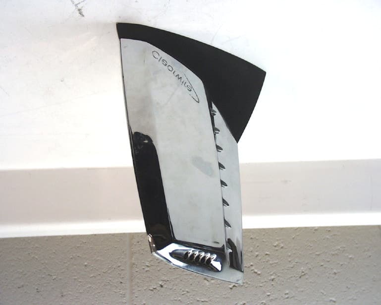
Click to zoom
Application Details
- Equipment Class
- DSS - Part 15 Spread Spectrum Transmitter
- Date of Grant
- Nov 12, 2001
- Application Purpose
- Original Equipment
- Date of Application
- Nov 12, 2001
- Equipment Note
- Fixed, Point-to-Point 2.4 GHz DSSS Transceiver
- Frequency Range
- 2408.04000000 - 2465.32800000
- Company
- Clearwire Technologies Inc
- Country
- United States
Documents & Files
Document Text
Text extracted from the exhibit documents filed with the FCC. Open a document above to read the original.
Users Manual
TOC-1 Click on upper PDF icon for an Acrobat Reader printable/viewable version of this chapter. Click on lower PDF icon for an Acrobat Reader printable/viewable version of the entire manual. CPE INSTALLATION MANUAL Table of Contents revision 2.1 25-Sep-01 Software Version S2.3.0 Chapter 1 - INTRODUCTION describes the equipment and features of the Clearwire wireless network. Chapter 2 - INSTALLATION PLANNING describes site requirements, site survey procedures, and required tools and equipment for survey and installation. Chapter 3 - INSTALLATION PROCEDURES provides procedures for installing network equipment, including the antenna and outdoor unit (ODU), the indoor unit (IDU), power supply and wiring connections. It also provides instructions for system startup and configuration, and troubleshooting the installation. Chapter 4 - PARTS LIST identifies part numbers for the Clearwire wireless equipment. Chapter 5 - TROUBLESHOOTING describes troubleshooting network operation, including interpretation of IDU front panel LEDs, and correcting problems detected by the network manager. INTRODUCTION This manual explains how to install, troubleshoot Clearwire wireless equipment. This manual is intended for the person responsible for installing and maintaining the Clearwire wireless equipment. The procedures included herein should only be performed by qualified, trained personnel. FCC INFORMATION This device complies with Part 15 of the FCC Rules. Operation is subject to the following two conditions: (1) this device may not cause harmful interference and (2) this device must accept any interference received, including interference that may cause undesired operation. NOTE: This equipment has been tested and found to comply with the limits for a Class A digital device, pursuant to Part 15 of the FCC Rules. These limits are designed to provide reasonable protection against harmful interference when the equipment is operated in a commercial environment. This equipment generates, uses, and can radiate radio frequency energy and, if not installed and used in accordance with the instruction manual, may cause harmful interference to radio communications. Operation of this equipment in a residential area is likely to cause harmful interference in which case the user will be required to correct the interference at his own expense. RF EXPOSURE FOR ACCESSIBLE ANTENNA Warning: Changes or modifications not expressly approved by Clearwire could void the user’s authority to operate the equipment. WARNING: For compliance with the RF exposure requirements regulated by the FCC (Federal Communications Commission), the separation distance of more than 2 meters shall be maintained between the transmitter, and any part of the user’s body. TOC-2 TRADEMARKS: Clearwire is the trademark of Clearwire Equipment, LLC. Adobe, the Adobe logo, Acrobat, and the Acrobat logo are trademarks of Adobe Systems. Castle Rock SNMPc is a trademark of Castle Rock Computing. Windows 95, Windows 98, Windows NT, Windows 2000, Excel, Hyper Terminal are trademarks of Microsoft Corporation. Other brands and product names are the trademarks of their respective owners. THE SPECIFICATIONS AND INFORMATION REGARDING THE PRODUCTS IN THIS MANUAL ARE SUBJECT TO CHANGE WITHOUT NOTICE. ALL STATEMENTS, INFORMATION, AND RECOMMENDATIONS IN THIS MANUAL ARE BELIEVED TO BE ACCURATE BUT ARE PRESENTED WITHOUT WARRANTY OF ANY KIND, EXPRESS OR IMPLIED. IN NO EVENT SHALL CLEARWIRE EQUIPMENT OR ITS SUPPLIERS BE LIABLE FOR ANY INDIRECT, SPECIAL, CONSEQUENTIAL, OR INCIDENAL DAMAGES, INCLUDING WITHOUT LIMITATION, LOST PROFITS OR LOSS OR DAMAGE TO DATA ARISING OUT OF THE USE OR INABILITY TO USE THIS MANUAL, EVEN IF CLEARWIRE EQUIPMENT OR ITS SUPPLIERS HAVE BEEN ADVISED OF THE POSSIBILITY OF SUCH DAMAGES.
Users Manual
Chapter 1-1 Click on this icon for an Acrobat Reader printable/viewable version of this chapter. CPE INSTALLATION MANUAL Chapter 1 revision 2. 1 25-Sep-01 Software Version 2.3.0 TOPICS: Overview Features Equipment Supplied Glossary OVERVIEW / DESCRIPTION The Clearwire Wireless Access Server is a multiple access, wireless, metropolitan area network device that enables ISP’s to provide their subscribers direct local Internet access. Figure 1-1 shows a typical Clearwire network. Each Clearwire subscriber site has a radio link to the ISP, either direct or through a base station. Customer Premise Equipment (CPE) at each subscriber site includes an antenna with co-located Outdoor Unit (ODU), and an Indoor Unit (IDU). Figure 1-1 Typical Clearwire Wireless Network Chapter 1-2 FEATURES: • Internet Connection - Secure, carrier class connection for Internet, intranet, extranet, virtual private network access, and all IP applications. • Wireless - Real time configurable and controllable software radio • 100Base-T 802.3 Ethernet connection to subscriber LAN using TCP/IP protocol. • No router required. • 100% reliable connection with retransmissions. • Broadband — Up to 2 Mbps to each customer. • Radios operate in Industrial, Scientific and Medical (ISM) spectrum (2.4000 — 2.4835 GHz) under FCC Regulation Part 15.247. No license is required in the U. S. and Canada. • Frequency tunable Direct Sequence Spread Spectrum (DSSS) waveform for interference rejection. • Reed-Solomon error correction encoding and decoding for accurate data transmission. • Scalability - Add users and base stations as needed to cover a large metropolitan area. • Network Management — Real time configuration control and monitoring by network manager at ISP site. • Customized SNMP compatible network management software, supporting MIB II, and enterprise specific MIB for configuration and monitoring. • Over-the-network upgrades of base station and CPE software. Chapter 1-3 EQUIPMENT SUPPLIED: Clearwire CPE hardware for subscriber sites includes the IDU, power supply, ODU/ antenna (one of two types), and connecting cables. • Indoor Unit (IDU). The IDU is a computation capable radio. Its processor, a high speed communications engine, is capable of running standard TCP/IP and Ethernet protocol stacks as well as processing its node’s role in the proprietary Clearwire air protocol. Processing includes precision timing, error control, and radio configuration/control. Figure 1-2 shows the IDU front panel. Table 1-1 describes the front indicators. Figure 1-3 shows the IDU bottom panel. Table 1-2 describes the bottom panel connectors. Figure 1-2 IDU STATUS Blue— Lit indicates power on. FAULT IDU — Lit indicates IDU fault detected by self test. Table 1-1 LEDs Chapter 1-4 Figure 1-3 IDU Bottom View DC PWR Power input port (+5V DC power from power supply). LAN 10Base-T Ethernet LAN connection port. RF RF connection port (cable connection to ODU) Table 1-2 Bottom Panel Connectors Chapter 1-5 • ASY_Power 5V Power Supply. The power supply (see Figure 1-4) uses 95 to 250 Vac, 47 to 63 Hz power to provide +5V and ±12V DC power to the IDU. Figure 1-4 Power Supply Chapter 1-6 • The ODU is included as part of the antenna assembly (see Figure 1-5) and contains the receiver front end and the final stage of transmit power amplification. Power, signal and control all flow through a single thin coax cable to allow remote ODU location without a separate power source. Connector J1 is used for connection to the IDU by coax cable. Connector J2 is permanently attached to the antenna port by coax cable. Figure 1-5 ODU (for illustration only, Part of the Antennae Chapter 1-7 • ANT_3X3 High Gain Panel Antenna Assembly. The high gain panel antenna assembly (see Figure 1-6) is usually used for sites 1 to 25 miles from the base station, with minimal signal path obstructions. It comprises a Clearwire panel antenna, permanently connected to the ODU. Figure 1-6 ANT_3X3 High Gain Panel Antenna Chapter 1-8 • ANT_CONIFER High Gain Reflector Antenna Assembly. The high gain reflector antenna assembly (see Figure 1- 7) is usually used for sites 6 to 25 miles from the base station, with moderate signal path obstructions. It comprises a Conifer 26T-2400 reflector antenna, permanently connected to the ODU. Figure 1-7 ANT_CONIFER High Gain Reflector Antenna Chapter 1-9 Glossary BER Bit Error Rate CPE Customer Premise Equipment DBPSK Differential Binary Phase Shift Keying DQPSK Differential Quadrature Phase Shift Key IDU Indoor Unit ISM Industrial, Scientific and Medical ISP Internet Service Provider LAN Local Area Network MIB Management Information (data) Base ODU Outdoor Unit PVC Permanent Virtual Circuit SNMP Simple Network Management Protocol SVC Switched Virtual Circuit TCP/IP Transport Control Protocol/Internet Protocol WAN Wide Area Network
Users Manual
Chapter 2 - 1 Click on this icon for an Acrobat Reader printable/viewable version of this chapter. CPE INSTALLATION MANUAL Chapter 2 revision 2. 1 25-Sep-01 Software Version S2.3.0 TOPICS: Site Requirements Clearwire Site Survey Sheet Required Tools and Equipment Cable Selection SITE REQUIREMENTS: • General. Each subscriber site must meet the following criteria: • Located within the Basestation coverage area (this can be determined by the network manager using the Network Propagation Tool). • Has a suitable location for antenna mounting (usually a rooftop or tower, at a minimum of height of 3 meters ) with Line of Sight (LOS) to the base station. • Provides a suitable location for the IDU for connection to the customer LAN, with standard power outlet (95-250VAC, 47 - 63 Hz) available. • Initial Site Check. The Clearwire network manager performs the initial site check using the Network Propagation Tool. If the subscriber site is within the coverage area, the network manager provides the following information to the installer: • Bearing and range from subscriber site to base station. • Probable antenna type. RF EXPOSURE FOR ACCESSIBLE ANTENNA WARNING: For compliance with the RF exposure requirements regulated by the FCC (Federal Communications Commission), the separation distance of more than 2 meters shall be maintained between the transmitter, and any part of the user’s body. Chapter 2 - 2 • Site Survey. The installer performs a site survey with the appropriate client contact. You’ll need permission from the building manager or owner regarding the antenna and IDU locations, and the RF cable run between the two. Record the appropriate information on the Clearwire Site Survey Sheet. 1. Identify the IDU installation location. Keep in mind these considerations: a. There must be an AC outlet within 6 feet. b. The RF cable must be run to the antenna. c. The IDU must be connected to the customer’s LAN. 2. Perform a radio test to confirm a link to the ISP. NOTE: the IDU must be configured with the proper IDU IP address, subnet mask, Sector assignment, Tx and Rx channels and maintenance mode must be disabled. See the IDU configuration section in chapter 3 of this manual a. Set up a test antenna of the same type recommended by the network manager as close as possible to the selected antenna location. b. Connect the antenna to the test IDU. Using a GPS receiver or magnetic compass, point the antenna toward the bearing of the base station. c. Power up the test IDU and check the front panel LEDs. Normal Blue LEDs should be indicated with no FAULT LEDs. A good link should be indicated. If not, try any or all of the following; 1. Slowly rotate the antenna to maximize signal strength. 2. Move the antenna location to avoid interference or obstructions. This may include raising the antenna height. 3. Perform the Antenna Null Steering procedure (see appendix I) 4. Try to establish a link to a different base station, if available. 5. Try a higher gain antenna type. d. Once a solid link is indicated contact the Network manager to confirm and asses the quality of the link. 3. Identify the antenna installation location. Install the Outdoor Unit and Antenna for Compliance with FCC RF Safety Regulations at a minimum height of 3 meters. The Outdoor Unit is mechanically and permanently secured to the antenna as one complete assembly. The whole assembly is, at all times, required to be installed on the roof of the building, pointing outward, or on an antenna tower or mast located outside of the building. 4. The installation shall be performed by professional installers in accordance with Clearwire's procedures. The installer should note that while the Clearwire Access Server System is a metropolitan area multiple access networking system, the CPE end equipment is to be used exclusively for fixed, point-to-point operations. Consider the following while planning a CPE installation: a. Maximize antenna performance by keeping clear of obstructions. b. Minimize visual impact. c. Identify RF cable run and building entry point with aesthetics and system performance in mind. 5. Map out the RF cable run. Identify drilling locations, conduit runs, drop ceilings, etc. as needed. Determine the minimum length of cable required. Chapter 2 - 3 REQUIRED TOOLS AND EQUIPMENT: The CPE installer should have the following tools and equipment: • Site Survey Equipment – Test IDU, both antenna types (high gain reflector, and panel), connecting cables, GPS locator or magnetic compass, cell phone or radio, electrical extension cord. • Antenna Installation Equipment – Common hand tools including a drill, assorted wrenches and screwdrivers, necessary safety equipment, non metal, non conductive ladder, caulk and other sealing material. • Site Configuration Equipment - laptop computer or PC with JET terminal emulation application. • Cable cutting and stripping tools, Connector crimping tool and weatherproofing kits for RG6U. CABLE, CONNECTORS AND TOOLS: The Cable used on the G2CPE is of the RG6U type cable, specifically Belden 5339B5. This type is recommended due to the low DC resistance over length and consistent loss specifications at the IF frequencies. This cable can be installed in a continuous run of 10 to 300 feet. The cable is to be made (cut to length and ends installed) on-site. Under no circumstances should RG59U cable be used. The Outside diameter is wrong for the specified connector, the loss at IF frequencies varies from manufacturer to manufacturer and the DC resistance is too high for longer runs. The Connector specified to be used is Thomas and Belts “Snap N Seal”, part number SNS6. This connector was selected for ease of use and environmental integrity. The coax tool used for the coax preparation and connector installation can be obtained from Augut. The part number is Augut LRC IT1000. The Bottom end of the tool is used to strip and prepare the coax, and the top is used to crimp the Snap N Seal connector onto the coax. INSTAL…
Text truncated - open the document above for the full version.
Users Manual
Chapter 3 - 1 Click on this icon for an Acrobat Reader printable/viewable version of this chapter. CPE INSTALLATION MANUAL Chapter 3 revision 2. 1 25-Sep-01 Software Version S2.3.0 TOPICS: 1. Antenna Installation: - Safety Precautions - Site Preparation - Antenna Mounting - Grounding - RF Cable Run 2. IDU Installation 3. PC Communications 3. IDU Configuration 4. PC Configuration ANTENNA INSTALLATION: CAUTION: THE ANTENNA ASSEMBLY MUST BE INSTALLED BY AN AUTHORIZED, APPROVED CONTRACTOR IN ACCORDANCE WITH STATE AND LOCAL BUILDING AND ELECTRICAL CODES. RF EXPOSURE FOR ACCESSIBLE ANTENNA Warning: Changes or modifications not expressly approved by Clearwire Equipment could void the user’s authority to operate the equipment. WARNING: For compliance with the RF exposure requirements regulated by the FCC (Federal Communications Commission), the vertical separation distance of more than 2 meter sshall be maintained between the transmitter, and any part of the user’s body. Chapter 3 - 2 Figure 3-1 High Gain Panel Antenna Installation Figure 3-2 High Gain Reflector Antenna Installation Typical antenna installations WARNING: INSTALLING ANTENNAS NEAR POWER LINES IS DANGEROUS. FOLLOW THE MANUFACTURER’S INSTRUCTIONS IN ACCORDANCE WITH THE RECOMMENDATIONS OF THE U.S. CONSUMER PRODUCT SAFETY COMMISSION. Antenna installation includes the following: 1. Safety Precautions: • Check for overhead power lines before beginning installation. Stay at least twice the length of the antenna away from all power lines. TOUCHING MASTS, CABLES, METAL GUY WIRES, ANTENNAS OR ANY METAL OBJECT TO POWER LINES CAN CAUSE A FATAL SHOCK! • If any part of the installation comes in contact with a power line, DO NOT TOUCH IT OR TRY TO REMOVE IT! Call the local power company. • Do not use a metal ladder. • Avoid installing antennas on a windy day. • Properly ground the installation in accordance with state and local electrical codes. Chapter 3 - 3 2. Site preparation: 2. Site preparation: • Erect masts or towers with grounding systems in accordance with state and local codes. • Drill holes as needed and prepare antenna for mounting. • Drill and prepare RF cable access and cable run holes as needed. • Other custom mounting accommodations as needed (fabricate custom brackets or the like). 3. Antenna Mounting: • Mount antenna assembly on wall, mast or tower according to manufacturer’s instructions. NOTE: The antenna must be mounted for vertical polarization. • Point antenna toward the assigned cell site. For all antenna locations, point the antenna towards the designated cell site identified by the Network Manager. Use the methods described in the Site Survey section of Chapter 2 of this manual to maximize performance and minimize interference. 4. Grounding: • ROOFTOP INSTALLATIONS o Rooftop installations require 2-point grounding using #2 AWG solid copper wire. Bond to any of the following: ß Building steel or lightning protection ground wire. ß Cold water main. ß Ground conductor to exit or halo down. o Ground the RF cable at the entry to building or cabinet. • TOWER INSTALLATIONS o Ground all antennas at the top of the tower. Bond to the tower itself, or run a ground conductor down. o If the tower is over 200 feet tall, ground the RF cable at the middle of tower. o Ground the RF cable at the bottom of the tower. o Cadwelds underground. o Double lug compression above ground. Bolts must be stainless steel. o Kopr-Shield all mechanical interfaces. o 2-Point grounding to inside of building. o Halo ground installed at least 18 in. below grade. o Halo comprised of #2 AWG tinned solid copper wire. o Test the grounding system to prove system less than 10 ohms. o All grounds should "flow downstream" with minimum bend radius (6 in. for #6, 12 in. for #2). o Halo must have 10 ft. ground rods driven down approximately every 10 ft. Rods must be 5/8 in. steel clad with pure copper not less than 0.0012 in. Chapter 3 - 4 5. RF Cable Run: • Run RF cable from antenna to IDU location, again keeping aesthetics in mind. Make it as unobtrusive as possible. • Form a drip loop close to where the cable enters the building. Caulk and seal around the entrance. • Connect the RF cable to the ODU and weatherproof the connection following the Installation Instructions in Chapter 2. IDU INSTALLATION: Once the antenna assembly is installed and the RF cable is run, install the IDU as follows. 1. Connect the RF cable to the IDU RF connector. 2. Plug the subscriber Ethernet LAN connector into the IDU LAN port. When connecting to the LAN via a hub, use a straight through cable (standard). When connecting directly to a PC, use a crossover cable. 3. Connect the power supply output to the IDU DC PWR connector. 4. Install JET (Java Ethernet Terminal Program) on the PC in accordance with the JET procedure listed below, and start the program. 5. Plug the power supply into an AC outlet to power up the IDU. Check the IDU Indicator LEDs. The PWR and CPU LEDs should be lit, and blinking (blue), and FAULT LEDs (red) should be off, and the LINK LED should be lit (yellow). (Note: The equipment may require up to 3 minutes to establish the link.) 6. Configure the IDU (using JET) with the proper IDU IP Address and Ethernet Host Address (if using NAT) in accordance with the procedure below 7. Once a link is established, contact the network manager to confirm the link and complete the IDU configuration. Chapter 3 - 5 CONFIGURATION: Before beginning normal operation you should perform a communications test. You then must perform, the PC configuration, and the IDU configuration. PC Communications: Each participating PC on the subscriber LAN must be properly configured for connection to the Internet using Clearwire Wireless. Table 3-1 lists the information you’ll need before configuring each PC. Obtain this information from your ISP Direct network manager. Table 3-1 - PC Configuration Information Site Name IP Address of Clearwire G2CPE IDU (Gateway) Available IP range for this site (…
Text truncated - open the document above for the full version.
Users Manual
Chapter 4 - 1 Click on this icon for an Acrobat Reader printable/viewable version of this chapter. CPE INSTALLATION MANUAL Chapter 4 revision 2.0 Software version 2.3.0 Part Number Description Quantity G2CPE-SE1 Clearwire Customer Premise Equipment 1 .G2IDU-SE1 . Indoor Unit IDU 1 . ASY_PWR_5V . Power Supply (ELPAC W4232-D5) 1 . SCA-ST54PVU-568B . LAN Cable 1 .ANT_3X3 High Gain Panel Antenna Assembly 1 .G2ODU-SE1 ODU Assembly 1 ..9714-2740-1 or 2" Ubolt Mounting Kit 2 ..9714-2760-1 or Pole Strap Mount Kit 2 ..9714-2770-1 or Azimuth Mount Kit 1 ..9714-2780-1 or Down Tilt Mount Kit 1 Supplied by Installer Antenna Grounding Strap ..ANT_CONIFER High Gain Reflector Antenna Assembly 1 .G2ODU-SE1 ODU Assembly 1 ..9714-2740-1 or 2" Ubolt Mounting Kit 2 Supplied by Installer Antenna Grounding Strap .CAB_RG6U Assy Supplied by Installer Antenna Grounding Strap Chapter 4 - 2
Users Manual
Chapter 5 - 1 Click on this icon for an Acrobat Reader printable/viewable version of this chapter. CPE INSTALLATION MANUAL Chapter 5 revision 2.1 25-Sep-01 Software version S2.3.0 TOPICS: Panel LEDs Faults detected by network manager FAULTS DETECTED BY INTERNAL SELF TESTING: THIS SECTION IS UNDER DEVELOPMENT FAULTS DETECTED BY NETWORK MANAGER: The network manager can remotely detect and diagnose a variety of faults and conditions. This may lead directly to identification of a component to be replaced, or may require on-site troubleshooting while in contact with the network manager.
Cover Letter(s)
Sep.03, 2001 TIMCO ENGINEERING INC. P.O. Box 370 849 N.W. State Road 45 Newberry, Florida 32669 Subject:FCC Certification Authorization Application under FCC PART 15, Subpart C, Sec. 15.247 - Direct Sequence Spread Spectrum Transmitters operating in the frequency band 2408.040 - 2465.328 MHz. Product:Clearwire G2 Access Server (Fixed, Point-to-Point 2.4 GHz DSSS Transceiver) Model No.:G2IDU-SE1 FCC ID:NUXG2CPE-SE1 Dear Sir/Madam As appointed agent for CLEARWIRE TECHNOLOGIES INC., we would like to submit the application to the Federal Communications Commission for certification of the above product. Please review all necessary files uploaded to FCC OET site for detailed information. • Compliance with RF Exposure Requirements: - The transmitter complies with FCC 2.1091 with the minimum RF safety distance of 2 meters. Please refer to Chapters 0, 2 & 3 of the Users Manual for details of the antenna installation instruction for details. - The antenna is required to be professionally installed by the manufacturer or parties who are trained to install the antenna for ensuring compliance with the RF exposure requirements. If you have any queries, please do not hesitate to contact us. Yours truly, Tri Minh Luu, P. Eng., V.P., Engineering Encl 2 3000 Bristol Circle Oakville, Ontario, Canada L6H 6G4 Telephone (905) 829-1570 Facsimile (905) 829-8050 Website: www.ultratech-labs.com Email: [email protected] [email protected] UltraTech Group of Labs
Cover Letter(s)
C:\windows\TEMP\probonholdemail.doc TIMCOTIMCO ENGINEERING INC. 849 NW State Road 45 Newberry, Florida 32669 http://www.timcoengr.com 888.472.2424 F 352.472.2030 email: [email protected] 13 November 2001 FCC SUBJECT: CLEARWIRE TECHNOLOGIES INC. FCC ID: NUXG2CPE-SE1 To Whom It may Concern, The photographs show a indoor portion to this system, the indoor unit does not have RF output. The RF Power output is only for the outdoor unit. The antenna is always mount outdoors at a height that insures 2.0 meters separation from any person. Sincerely, Sid Sanders
Cover Letter(s)
FCCID: NUXG2CPE-SE1 1 of 1 Authorization Exhibit Clearwire Equipment, LLC Voice 716-631-4545 485 Cayuga Road Fax 716-631-6080 Buffalo, New York 14225-0850 Subject: Request for withholding from public disclosure the schematic diagrams and system block diagrams pursuant to an application for certification. Federal Communications Commission Authorization and Evaluation Division 7435 Oakland Mills Road Columbia, MD 21046 August 11, 2001 To whom it may concern: As appointed agent for Clearwire Equipment, LLC, we would like to request that the schematic diagrams and system block diagrams, labeled Exhibit Schematic and Exhibit Theory of Operation submitted with the application for certification be withheld from public disclosure as per Section 0.459 of FCC Rules. This request is made under the provisions of Section 0.457(d) of the Commissions Rules, and Section 552(b)(4) of the Freedom of Information Act. These section authorize as a withholding from public inspection material which would be privileged as a matter of law if retained by the person submitting them, and materials which would not customarily be released to the public by that person The detailed confidential materials are listed as follows: No. Title Drawing number Sheet No. 1 Schematic Diagram, Radio Outdoor Digital G2CPE-SE1-ODU1-5.JPG 1 TO 5 2 Schematic Diagram, Radio Outdoor RF G2CPE-SE1-ODU6-8.JPG 1 TO 3 3 Theory of Operation THEORY OF OPERATION 1 TO 19 If you have any questions regarding this notification, please do not hesitate to contact the undersigned at the phone number, address and/or email address listed. Sincerely Yours, David Chauncey CTO [email protected]
External Photos
ANNEX 3 - EXTERNAL PHOTOGRAPHS OF THE EQUIPMENT UNDER TESTSPHOTO # 1 Clearwire Model G2IDU-SE1 – Indoor Unit ANNEX 3 - EXTERNAL PHOTOGRAPHS OF THE EQUIPMENT UNDER TESTSPHOTO # 2 Clearwire Model G2IDU-SE1 – Indoor Unit
External Photos
ANNEX 3 - EXTERNAL PHOTOGRAPHS OF THE EQUIPMENT UNDER TESTSPHOTO # 3 Clearwire Model G2IDU-SE1 – Outdoor Unit ANNEX 3 - EXTERNAL PHOTOGRAPHS OF THE EQUIPMENT UNDER TESTSPHOTO # 4 Clearwire Model G2IDU-SE1 – Outdoor Unit
External Photos
ANNEX 3 - EXTERNAL PHOTOGRAPHS OF THE EQUIPMENT UNDER TESTSPHOTO # 5 Andrew Model 26T-2400 Mag Grid (Conifer) Antenna, Antenna Gain: 24 dBi maximum ANNEX 3 - EXTERNAL PHOTOGRAPHS OF THE EQUIPMENT UNDER TESTSPHOTO # 6 Andrew Model 26T-2400 Mag Grid (Conifer) Antenna, Antenna Gain: 24 dBi maximum ANNEX 3 - EXTERNAL PHOTOGRAPHS OF THE EQUIPMENT UNDER TESTSPHOTO # 7 Huber & Suhner 3”x3” Patch Monoband Antenna, Model SPA 2400/27/17 ANNEX 3 - EXTERNAL PHOTOGRAPHS OF THE EQUIPMENT UNDER TESTSPHOTO # 8 Huber & Suhner 3”x3” Patch Monoband Antenna, Model SPA 2400/27/17
ID Label/Location Info
485 Cayuga Rd., Buffalo, NY 14225 Phone: (716) 631-6600; Fax: (716) 631-6080 Annex7- FCCA-Label-Location 2/18/99HR.7024.FRM Placement of FCC Compliance Label for G2IDU-SE1.
ID Label/Location Info
485 Cayuga Rd., Buffalo, NY 14225 Phone: (716) 631-6600; Fax: (716) 631-6080 ODU - FCC Label Placement 2/18/99HR.7024.FRM Placement of FCC Compliance Label for G2ODU-SE1.
Internal Photos
Annex 4 - Internal Photographs of Clearwire Model G2IDU-SE1 – Indoor UnitPhoto # 1 Annex 4 - Internal Photographs of Clearwire Model G2IDU-SE1 – Indoor UnitPhoto # 2
Internal Photos
Annex 4 - External Photographs of Clearwire Model G2IDU-SE1 – Indoor UnitPhoto # 3 Annex 4 - External Photographs of Clearwire Model G2IDU-SE1 – Indoor UnitPhoto # 4 Annex 4 - External Photographs of Clearwire Model G2IDU-SE1 – Indoor UnitPhoto # 5 Annex 4 - External Photographs of Clearwire Model G2IDU-SE1 – Indoor UnitPhoto # 6
Test Report
Sep.03, 2001 CLEARWIRE TECHNOLOGIES INC. 485 Cayuga Road, P.O. Box 222 Buffalo, New York USA, 14225-0222 Attn.:Mr. David Chauncey Subject:FCC Certification Application Testing under FCC PART 15, Subpart C, Sec. 15.247 - Direct Sequence Spread Spectrum Transmitters operating in the frequency band 2408.040 - 2465.328 MHz. Product:Clearwire G2 Access Server (Fixed, Point-to-Point 2.4 GHz DSSS Transceiver) Model No.:G2IDU-SE1 FCC ID:NUXG2CPE-SE1 Dear Mr. Chauncey, The product sample, as provided by you, has been tested and found to comply with FCC PART 15, Subpart C, Sec. 15.247 - Direct Sequence Spread Spectrum Transmitters operating in the frequency band 2408.040 - 2465.328 MHz. • Compliance with RF Exposure Requirements: - The transmitter complies with FCC 2.1091 with the minimum RF safety distance of 2 meters. Please refer to Chapters 0, 2 & 3 of the Users Manual for details of the antenna installation instruction for details. - The antenna is required to be professionally installed by the manufacturer or parties who are trained to install the antenna for ensuring compliance with the RF exposure requirements. Enclosed you will find copies of the engineering report. If you have any queries, please do not hesitate to contact us. Yours truly, Tri Minh Luu, P. Eng., V.P., Engineering Encl 2 3000 Bristol Circle Oakville, Ontario, Canada L6H 6G4 Telephone (905) 829-1570 Facsimile (905) 829-8050 Website: www.ultratech-labs.com UltraTech Group of Labs Clearwire G2 Access Server (Fixed, Point-to-Point 2.4 GHz DSSS Transceiver) Model No.: G2IDU-SE1 FCC ID: NUXG2CPE-SE1 Applicant: CLEARWIRE TECHNOLOGIES INC. 485 Cayuga Road, P.O. Box 222 Buffalo, New York USA, 14225-0222 In Accordance With FEDERAL COMMUNICATIONS COMMISSION (FCC) PART 15, SUBPART C, SEC. 15.247 Direct Sequence Spread Spectrum Transmitters operating in the frequency band 2408.040 - 2465.328 MHz UltraTech's File No.: IAW-019FCC15C This Test report is Issued under the Authority of Tri M. Luu, Professional Engineer, Vice President of Engineering UltraTech Group of Labs Date: Sep.03, 2001 Report Prepared by: Tri M. Luu . Tested by: Hung Trinh, RFI/EMI Technician Issued Date: Sep.03, 2001Test Dates: Aug. 28 - Sep. 04, 2001 The results in this Test Report apply only to the sample(s) tested, and the sample tested is randomly selected. UltraTech 3000 Bristol Circle, Oak…
Text truncated - open the document above for the full version.
Contact Information
Applicant
Dave Chauncey(Director RF Engineering)
Test Firm
UltraTech Engineering Labs Inc.Tri Luu
Technical Specifications
| # | Rule Parts | Frequency Range | Power Output |
|---|---|---|---|
| 1 | 15C | 2.41 GHz - 2.47 GHz | 174.00 mW |
Other Applications from Clearwire Technologies Inc
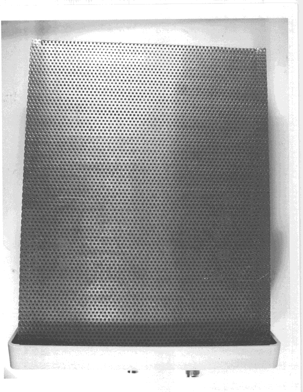
NUX-ISP2401-2
Apr 01, 1999DSS - Part 15 Spread Spectrum Transmitter
Equipment Class
DSS - Part 15 Spread Spectrum Transmitter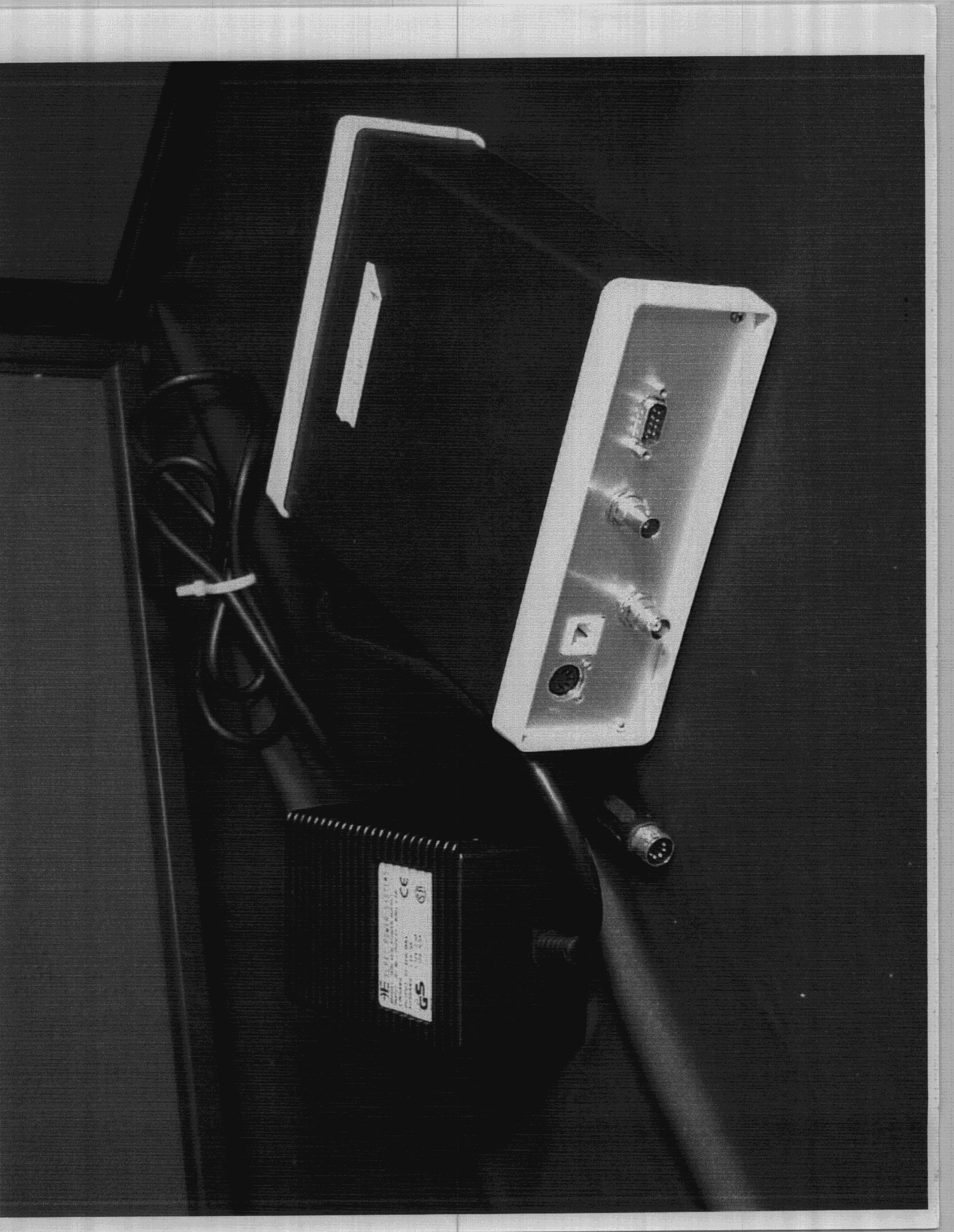
NUX-ISP2401
Aug 18, 1998LAN transmitter
Equipment Class
DSS - Part 15 Spread Spectrum Transmitter