NY8A2588Wireless Access Point
Emtac Technology Corp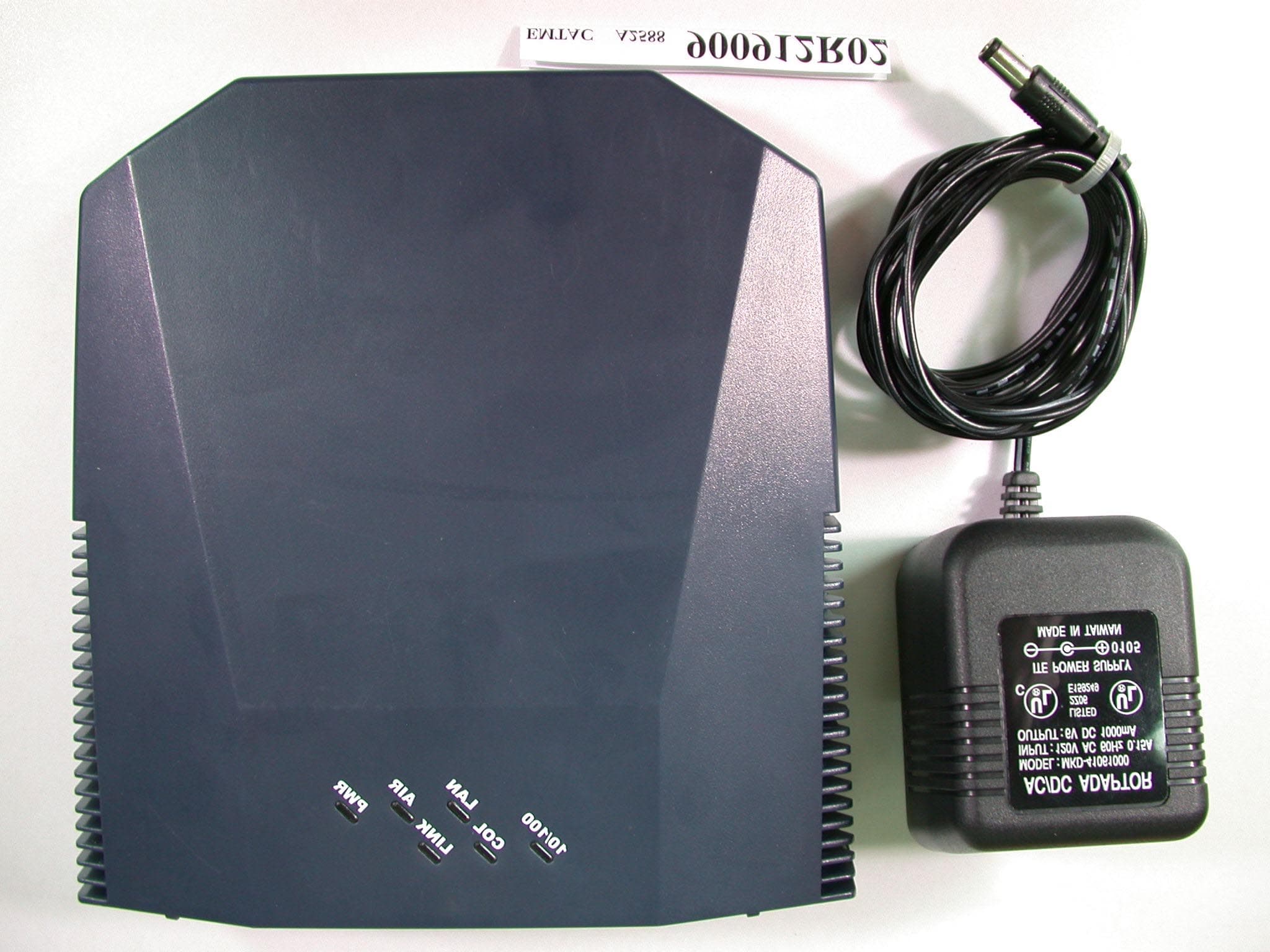
Click to zoom
Application Details
- Equipment Class
- DTS - Digital Transmission System
- Date of Grant
- Oct 08, 2001
- Application Purpose
- Original Equipment
- Date of Application
- Oct 08, 2001
- Equipment Note
- Wireless Access Point
- Frequency Range
- 2412.00000000 - 2462.00000000
- Company
- Emtac Technology Corp
- Country
- Taiwan
Documents & Files
Document Text
Text extracted from the exhibit documents filed with the FCC. Open a document above to read the original.
Users Manual
0 INSTALLATION MENU Wireless LAN Access Point 2.4 GHz / 11 Mbps / DSSS PN:A2588 1 FCC INFORMATION The Federal Communication Commission Radio Frequency Interference Statement includes the following paragraph: This equipment has been tested and found to comply with the limits for a Class B digital Device, pursuant to part 15 of the FCC Rules. These limits are designed to provide reasonable protection against harmful interference in a residential installation. This equipment generates, uses and can radiate radio frequency energy and, if not installed and used in accordance with the instruction, may cause harmful interference to radio communication. However, there is no guarantee that interference will not occur in a particular installation. If this equipment does cause harmful interference to radio or television reception, which can be determined by turning the equipment off and on, the user is encouraged to try to correct the interference by one or more of following measures: n Reorient or relocate the receiving antenna. n Increase the separation between the equipment and receiver. n Connect the equipment into and outlet on a circuit different from that to which the receiver is connected. n Consult the dealer or an experienced radio/TV technician for help. 2 This device complies with Part 15 of the FCC Rules. Operation is subject to the following two conditions: (1) This device may not cause harmful interference, and (2) This device must accept any interference received, including interference that may cause undesired operation. Radiation Exposure: This equipment complies with FCC RF radiation exposure limits set forth for an uncontrolled environment. This equipment should be installed and operated with a minimum distance of 20 centimeters between the radiator and your body. The user should not modify or change this equipment. Modification could void authority to use this equipment. 3 Notice The information in this document is subject to change in order to improve reliability, design, or function without prior notice and does not represent a commitment. No part of this document may be reproduced or transmitted in any form or by any means. Trademark Acknowledgments PRISM 2 is registered trademark of Intersil, Inc. Microsoft Windows are registered trademarks of Microsoft Corp. IBM and Thinkpad are a registered trademark s of International Business Machines Corp. All other product names or trademarks are property of their respective owners. Product and cooperate names mention in this publication are used for identification purpose only. 4 Package Contents The package should contain following items: 1. The EMTAC A2588 11Mbps WLAN Access Point. 2. Driver disc. 3. This menu. 4. USB cord 5. Power Adapter External Interface 1. USB Cord 2. Ethernet Cord 5 Software Installation Guide You should have an Access Point driver disk from our agent, it includes 2 major programs, one is “DFU” using USB port, and the other is “AP Configuration” using Ethernet port. For DFU 1. Run the “Setup.exe” in the folder of DFU of the driver disk. Follow the guideline on the screen, and select the directory where the application will be installed, it will deploy all files that needed at that. At the end, windows will show a message that installation is completed. 2. Power on the Access point. 3. After Access Point had powered on, then plug USB cord into both port of host PC and AP. 4. You can run the program of “DFU”, which you can find in “start” ‡”program” ‡”Atmel Utilities” ‡”DFU”. When the DFU is working correctly, it will tell you what both version of the Access Point firmware and this utility. 6 For AP Configuration 1. Run the “Setup.exe” in the folder of AP Configuration of the driver disk. Follow the guideline on the screen, and select the directory where the application will be installed, it will deploy all files that needed at that. At the end, windows will show a message that installation is completed. 2. Power on the Access point. 3. Plug the “cross over” type Ethernet cord into both port of host PC and AP. (If you don’t have “cross over” type Ethernet cord and have a hub, then you can use normal type Ethernet cable to connect both host PC and AP to hub.) 4. You can run the program of “AP Configuration”, which you can find in “start” ‡”program” ‡”Atmel Utilities” ‡”AP Configuration” 5. Make sure that the IP address of your host PC and AP are in the same sub-net, because this program is based on SNMP. The default setting of IP address of AP is 192.168.0.251 7 Utilities Using Guide Basic Configuration We highly recommend you that using “DFU” utility for the first time setting of AP, and “AP Configuration” for latter regular setting, (of course, you should already have a connect with AP through the Ethernet cable). Because the DFU utility configures the AP through USB port, it won’t care about any setting inside the AP. So you can change any setting you need and make sure what all the setting of AP are. After that, you may deploy the AP in a not-easily-reachable working place, it is very inconvenient to connect host PC and AP by USB cord, but it should have an Ethernet cable to connected to. For DFU When you run the DFU, you will see a page like below. 8 Press “Configuration” to get the configuration of AP. Note: Don’t download any file to AP, it will cause AP crashed, except that your vendor give you the correct firmware file(, like *.rom) and told you to download it. Now, you can see all the setting of AP. 9 1. First, set the field of “Eth_IP_Address”, that is the IP address of this AP. You should make sure that the IP address is a valid address in your sub-net. 2. Set the field of “Eth_SubMask”, that is the sub-net mask of this sub-net. It should be the same with your sub-net. 3. Set the field of “Wirel_ESSID”, that is the Extended Service Set ID (ESSID) of this AP. All wireless stations want to connect with this AP must have the same ESSID. 4. Set the field of “Wirel_Channel”, that is the channel that this …
Text truncated - open the document above for the full version.
External Photos
Page 1 ANNEX PHOTOGRAPHS OF EUT Page 2 Page 3
Internal Photos
Page 4 Page 5
Internal Photos
Page 6 Page 7
Operational Description
FCC ID: NY8A2588 ADT No.900912R02 Operational Description The transmitter of the EUT (Wireless Access Point) is powered by power adapter and connected with notebook through RJ45 port. The antenna is Inverted-F Antenna. There is no antenna connector. Under normal use condition, the user has to keep at least 20cm separation distance between radiator and the body of the user. The other instruction, please have a look at the users manual. DSSS Information This device is Direct Sequence Spread Spectrum, the data is mixed by pseudorandom code which is an orthogonal code. The mixed data is digital modulated by BPSK and QPSK technique depends on the data rates. The CCK coding is applied for increasing the data rate, and also the processing gain will be increased. The bit rates are 1,2,5.5,11Mbps, the symbol rates are 1,1,1.375,1.375Mbps, the chip rates are always 11Mbps. So, the Chip/symbol is 11,11,8 and 8 respectively. Although is higher bit rate, the processing gain is lower than 10, but the CCK coding used in higher bit rate will provide 2.2dB coding gain.
Test Report
FCC ID: NY8A2588 Report No.: RF900912R02 1 Issued: September 20, 2001 FCC TEST REPORT REPORT NO.: RF900912R02 MODEL NO.: A2588 RECEIVED: Sept. 12, 2001 TESTED: Sept. 12 ~ Sept. 15, 2001 APPLICANT: EMTAC Technology Corp. ADDRESS: 1F, No.60, Lane 91, Tong-Mei Road, Hsinchu, Taiwan, R.O.C. ISSUED BY: Advance Data Technology Corporation LAB LOCATION: 47 14th Lin, Chiapau Tsun, Linko, Taipei, Taiwan, R.O.C. This test report consists of 48 pages in total. It may be duplicated completely for legal use with the approval of the applicant. It should not be reproduced except in full, without the written approval of our laboratory. The client should not use it to claim product endorsement by CNLA, NVLAP or any government agencies. The test results in the report only apply to the tested sample. 0528 Lab Code: 200102-0 FCC ID: NY8A2588 Report No.: RF900912R02 2 Issued: September 20, 2001 Table of Contents 1CERTIFICATION ...........................................................................................4 2SUMMARY OF TEST RESULTS...................................................................5 3GENERAL INFORMATION ...........................................................................6 3.1GENERAL DESCRIPTION OF EUT..............................................................6 3.2DESCRIPTION OF TEST MODES................................................................7 3.3GENERAL DESCRIPTION OF APPLIED STANDARDS ...............................7 3.4DESCRIPTION OF SUPPORT UNITS..........................................................8 4TEST TYPES AND RESULTS.......................................................................9 4.1CONDUCTED EMISSION MEASUREMENT ................................................9 4.1.1LIMITS OF CONDUCTED EMISSION MEASUREMENT.................................................... 9 4.1.2TEST INSTRUMENTS....................................................................................................... 9 4.1.3TEST PROCEDURES..................................................................................................... 10 4.1.4TEST SETUP .................................................................................................................. 10 4.1.5EUT OPERATING CONDITIONS..................................................................................... 11 4.1.6TEST RESULTS ..............................................................................................................12 4.2RADIATED EMISSION MEASUREMENT ...................................................18 4.2.1LIMITS OF RADIATED EMISSION MEASUREMENT ...................................................... 18 4.2.2TEST INSTRUMENTS..................................................................................................... 19 4.2.3TEST PROCEDURES..................................................................................................... 20 4.2.4TEST SETUP .................................................................................................................. 21 4.2.5EUT OPERATING CONDITIONS..................................................................................... 21 4.2.6TEST RESULTS ..............................................................................................................22 4.36DB BANDWIDTH MEASUREMENT ..........................................................26 4.3.1LIMITS OF 6dB BANDWIDTH MEASUREMENT.............................................................. 26 4.3.2TEST INSTRUMENTS..................................................................................................... 26 4.3.3TEST PROCEDURE........................................................................................................ 27 4.3.4TEST SETUP .................................................................................................................. 27 4.3.5EUT OPERATING CONDITIONS..................................................................................... 27 4.3.6TEST RESULTS ..............................................................................................................28 4.4MAXIMUM PEAK OUTPUT POWER ..........................................................32 4.4.1LIMITS OF MAXIMUM PEAK OUTPUT POWER MEASUREMENT ................................. 32 4.4.2INSTRUMENTS...............................................................................................................32 4.4.3TEST PROCEDURES ..................................................................................................... 33 4.4.4TEST SETUP .................................................................................................................. 33 4.4.5EUT OPERATING CONDITIONS..................................................................................... 33 4.4.6TEST RESULTS ..............................................................................................................34 4.5POWER SPECTRAL DENSITY MEASUREMENT......................................35 4.5.1LIMITS OF POWER SPECTRAL DENSITY MEASUREMENT ......................................... 35 4.5.2TEST INSTRUMENTS..................................................................................................... 35 4.5.3TEST PROCEDURE........................................................................................................ 36 4.5.4TEST SETUP .................................................................................................................. 36 4.5.5EUT OPERATING CONDITION ....................................................................................... 36 4.5.6TEST RESULTS ..............................................................................................................37 4.6BAND EDGES MEASUREMENT ................................................................41 FCC ID: NY8A2588 Report No.: RF900912R02 3 Issued: September 20, 2001 4.6.1LIMITS OF BAND EDGES MEASUREMENT .......................................…
Text truncated - open the document above for the full version.
Test Setup Photos
FCC ID: NY8A2588 Report No.: RF900912R02 46 Issued: September 20, 2001 5 PHOTOGRAPHS OF THE TEST CONFIGURATION CONDUCTED EMISSION TEST FCC ID: NY8A2588 Report No.: RF900912R02 47 Issued: September 20, 2001 RADIATED EMISSION TEST
Contact Information
Applicant
Alan Lin(Engineer)
Technical Contact
Advance Data Technology CorporationAlan Lane
[email protected]+886 3 327 0910
13-1, Lane 19, WenShan 3rd St. · Taoyuan · Taiwan
Test Firm
Bureau Veritas CPS (H.K.) Ltd. Taoyuan BranchRichard Chen
Technical Specifications
| # | Rule Parts | Frequency Range | Power Output |
|---|---|---|---|
| 1 | 15C | 2.41 GHz - 2.46 GHz | 41.00 mW |
Other Applications from Emtac Technology Corp
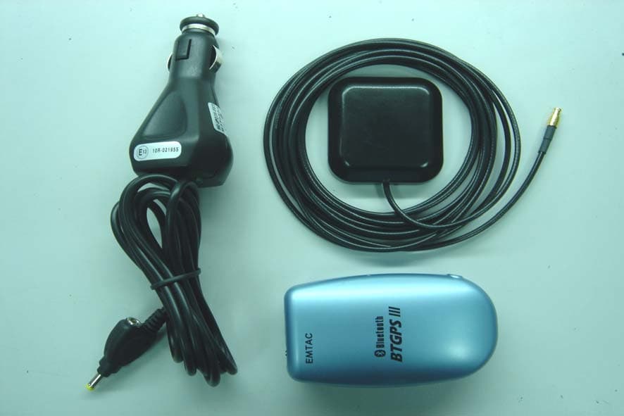
NY8D1599
Nov 02, 2004BTGPS III
Equipment Class
DSS - Part 15 Spread Spectrum Transmitter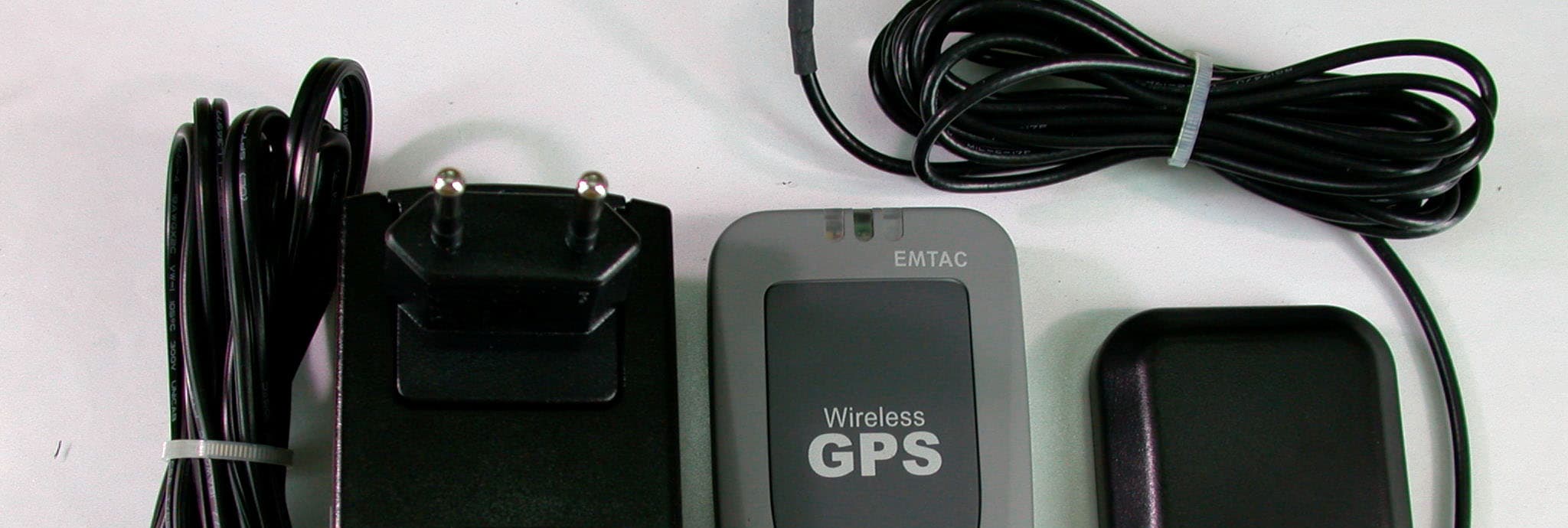
NY8D1598
Aug 13, 2002Bluetooth Wireless GPS
Equipment Class
DTS - Digital Transmission System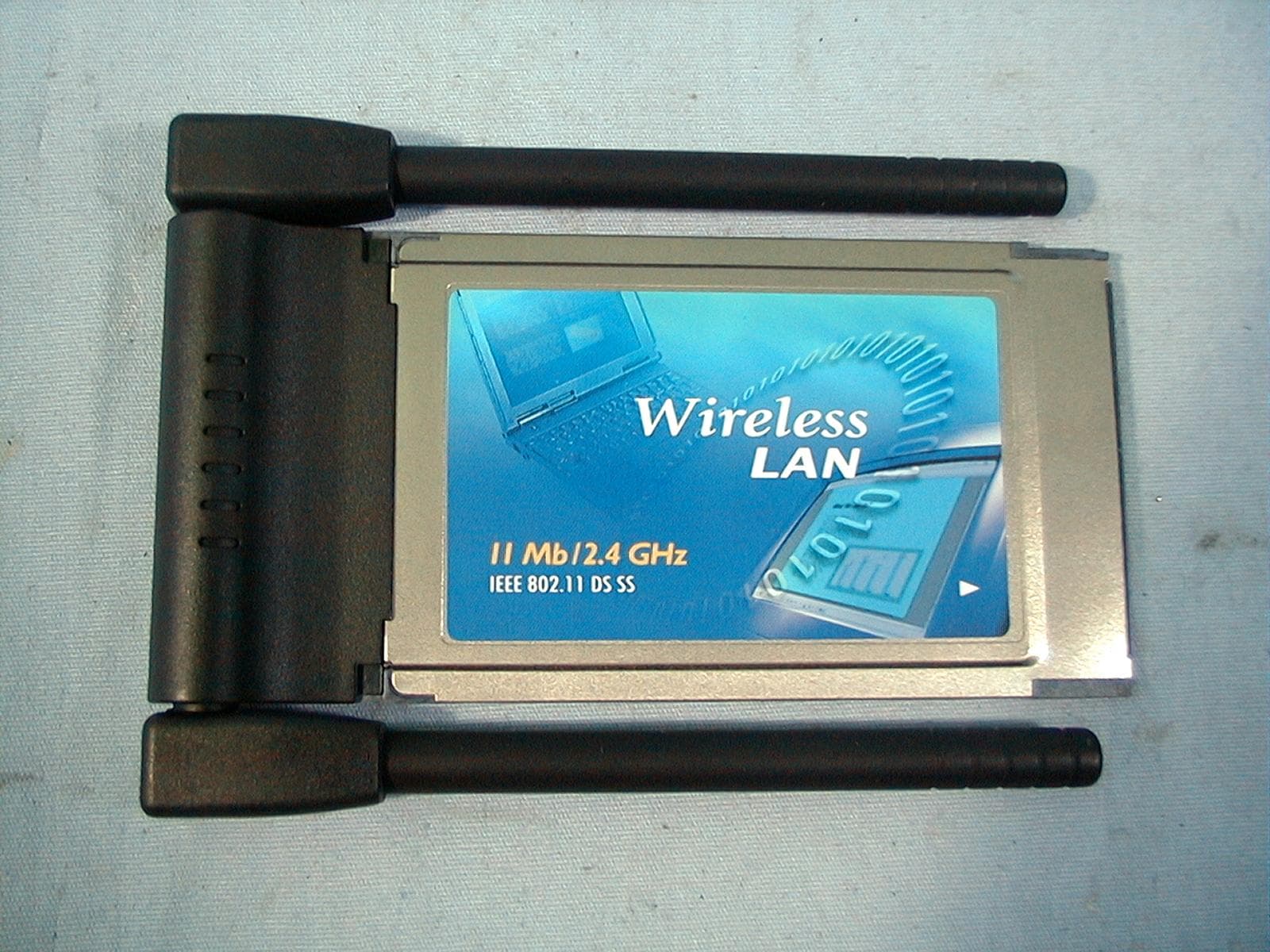
NY8A2424
Sep 26, 2000A 11Mpbs WLAN PC Card
Equipment Class
DSS - Part 15 Spread Spectrum TransmitterNY8A2422
Oct 08, 1998JBP - Part 15 Class B Computing Device Peripheral
Equipment Class
JBP - Part 15 Class B Computing Device Peripheral