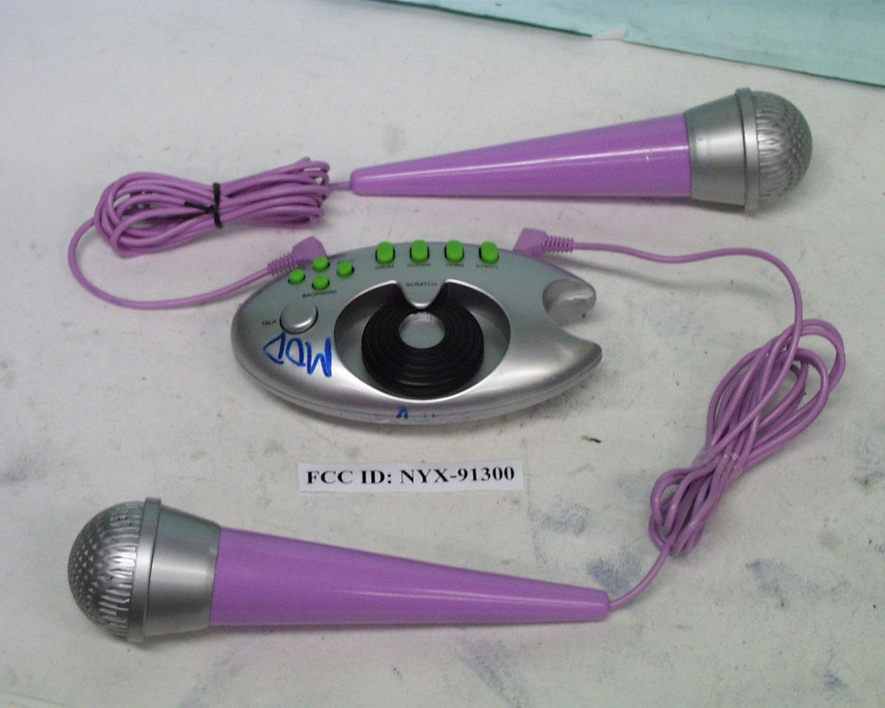
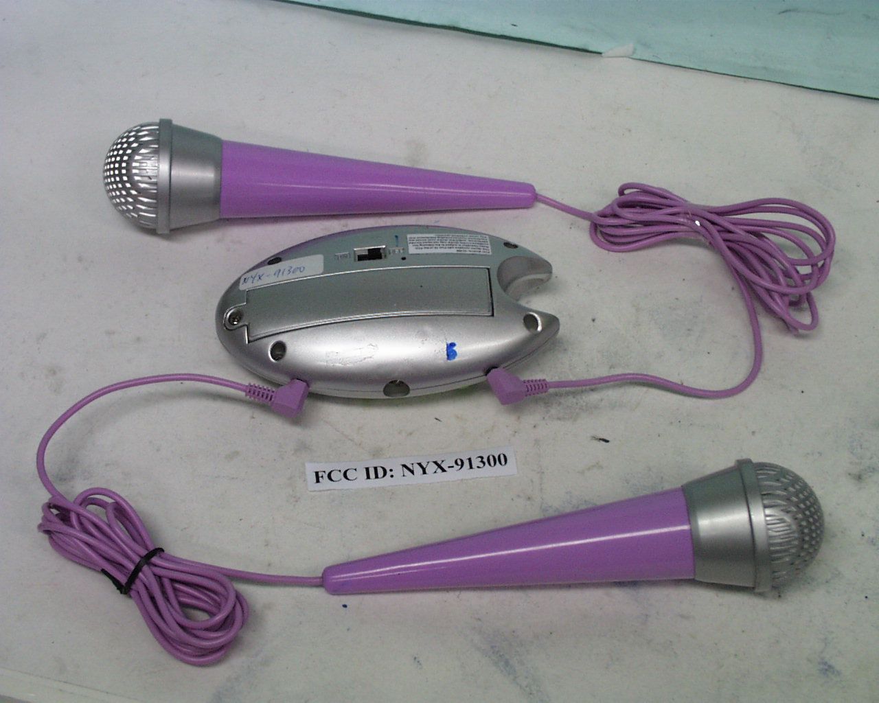
NYX-91300Radio Microphone
Trendmasters Inc.
Click to zoom
Application Details
- Equipment Class
- DXX - Part 15 Low Power Communication Device Transmitter
- Date of Grant
- Jul 06, 2001
- Application Purpose
- Original Equipment
- Date of Application
- Jul 06, 2001
- Equipment Note
- Radio Microphone
- Frequency Range
- 105.00000000 - 105.00000000
- Company
- Trendmasters Inc.
- Country
- Hong Kong
Documents & Files
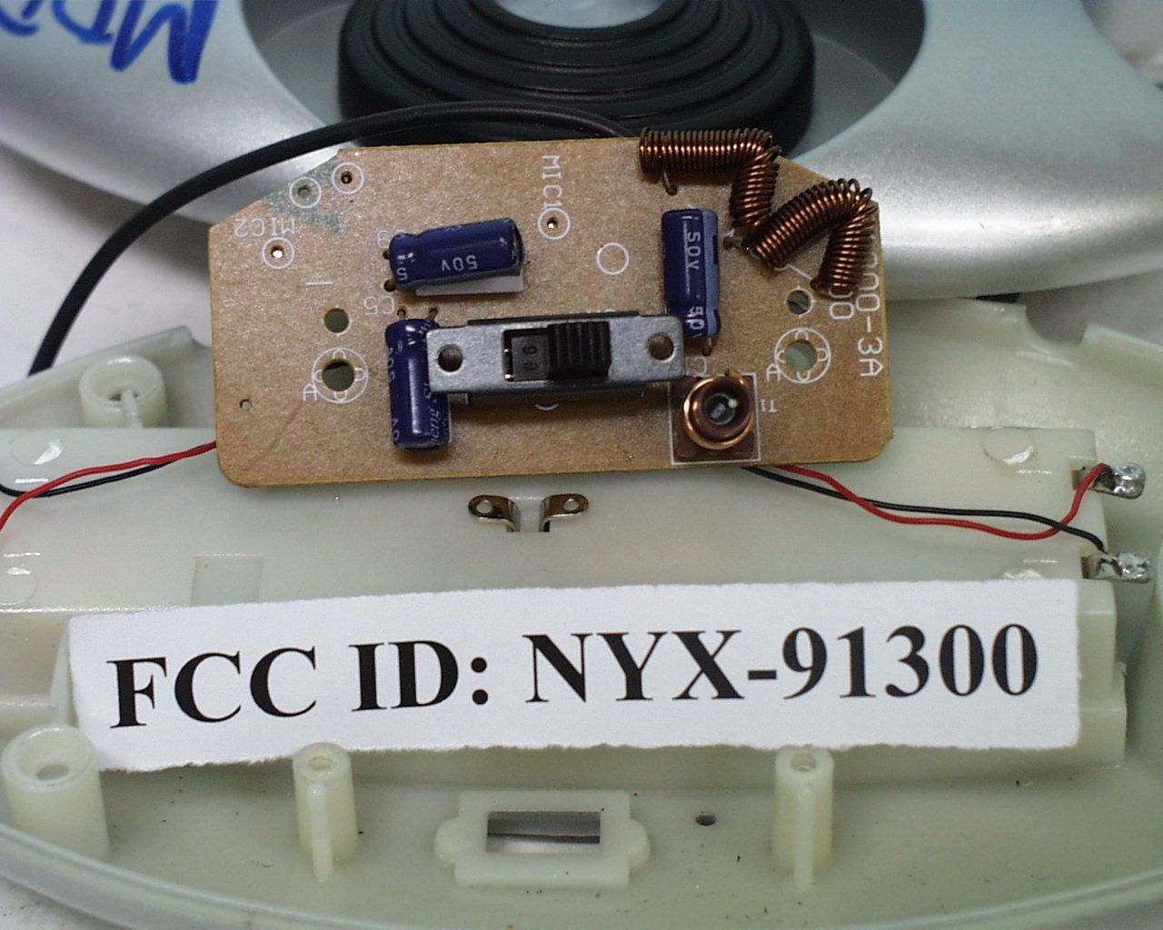
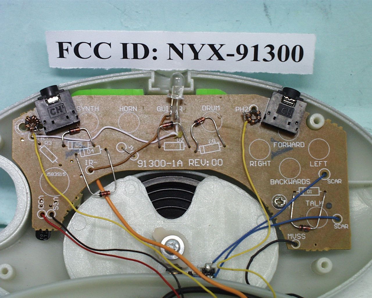
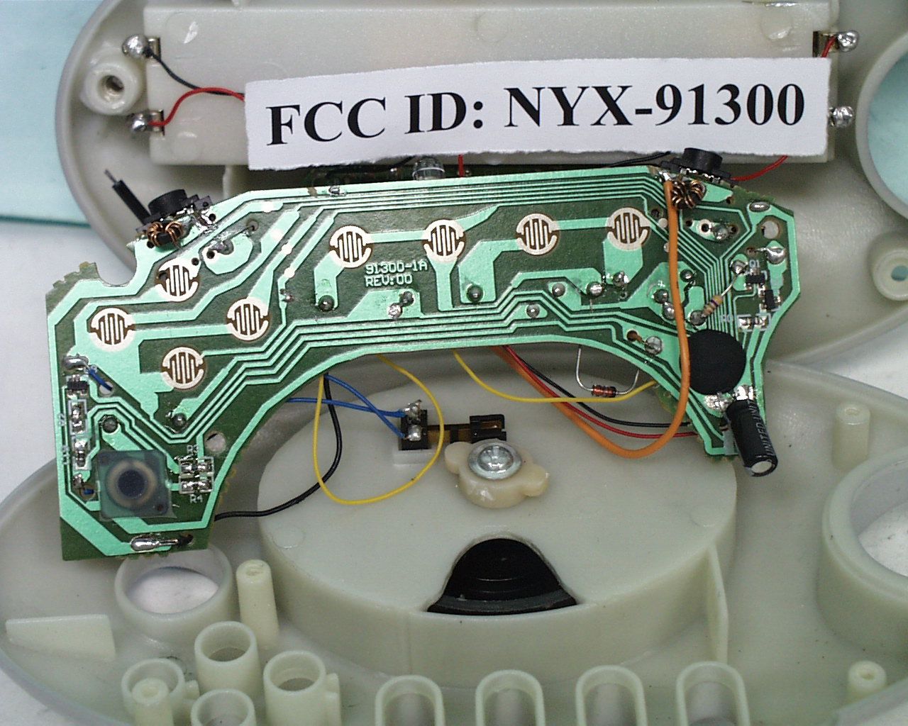
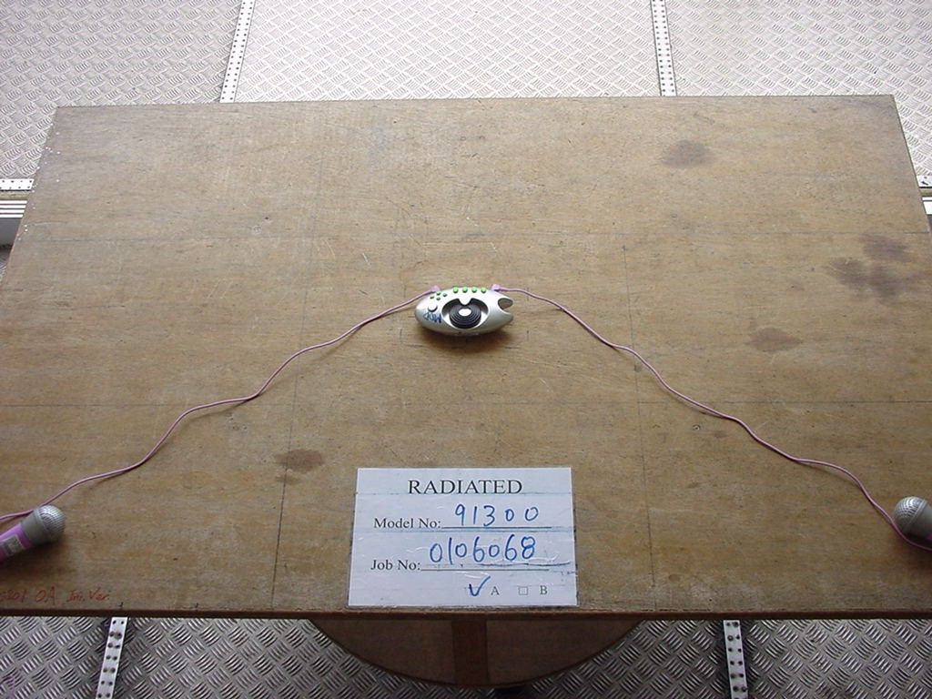
Document Text
Text extracted from the exhibit documents filed with the FCC. Open a document above to read the original.
Cover Letter(s)
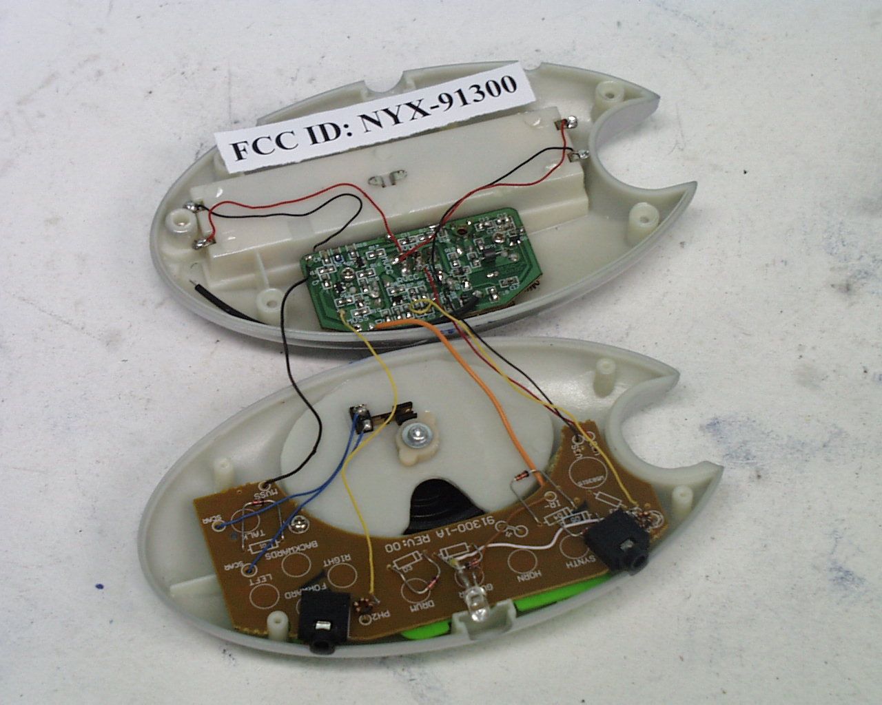
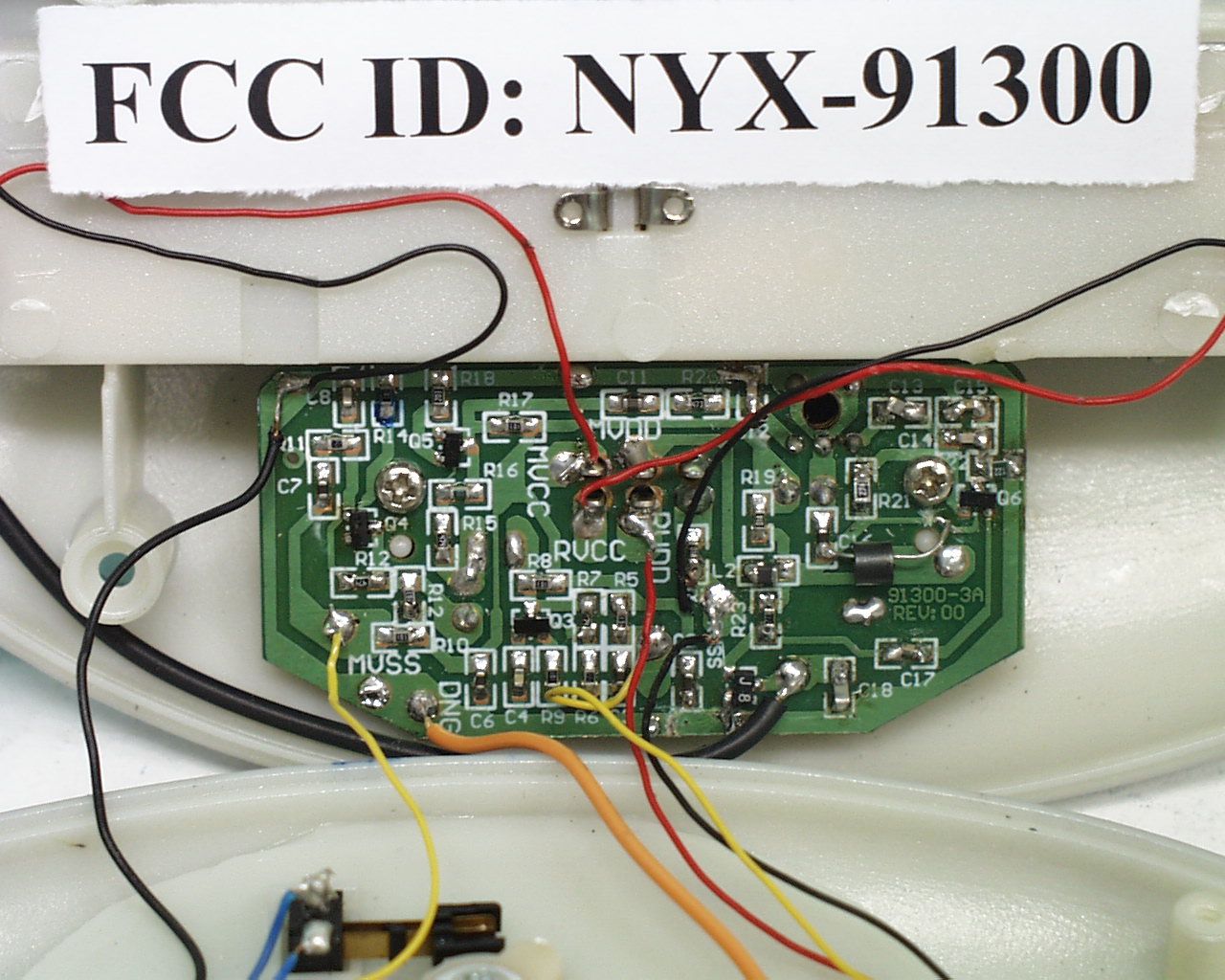
From: Ivan Wong ITS/ES-HKG Sent: Thursday, June 21, 2001 10:51 PM To: Roland Gubisch ITS/ES-Box Cc: Robert F. Martin ITS/ES-Box Subject: RE: FCC ID: NYX-91300 Dear Roland, Thank you for your comments, I would like to explain your question as belows: 1) The "Pop off" antenna is using on the receive unit only as show in the installation graph on the user manual. And the transmitter is using a internal wire antenna (the ruder black wire under the Surface Mount PCB) as show in the iphoto1.jpg. 2) There should be totally 5 internal photo (iphoto1.jpg-iphoto5.jpg), and the iphoto5.jpg shows the copper side (solder side) of the "C"-shape PCB. Maybe I missed sending to you, attached please find the file for your reference. 3) Yes, attached please find the bandwidth with 100kHz span, it show the span is less than 200kHz. Best regard, Ivan Wong -----Original Message----- From: Roland Gubisch ITS/ES-Box Sent: Friday, June 22, 2001 1:25 AM To: Lee Wing Yan ITS/ES-HKG Cc: Robert F. Martin ITS/ES-Box Subject: RE: FCC ID: NYX-91300 Dear Yan: Thank you for this application for a Part 15 transmitter in the FM broadcast band. Administrative review is complete, and the following are noted: 1) The user manual refers to a "pop off" antenna. The Operational description refers to an "internal wire antenna." Please explain this difference. Part 15 transmitters of this type must have a permanently-attached antenna. 2) The internal photos show only the component side of a "C"-shaped printed circuit board (iphoto1.jpg, iphoto4.jpg). Please provide a photo of the solder side of this circuit board. 3) The bandwidth plot confirms that the fundamental emission is wholly within the frequency range of 88-108 MHz, as required under 15.239(a). However, the plot does not demonstrate that the emission bandwidth is 200 kHz or less. Please provide another bandwidth plot with a much narrower span, perhaps 500 kHz, to demonstrate that the emission bandwidth is 200 kHz or less. Regards, Roland -----Original Message----- From: Lee Wing Yan ITS/ES-HKG Sent: Thursday, June 21, 2001 6:07 AM To: Roland Gubisch ITS/ES-Box Subject: FCC ID: NYX-91300 Dear Roland, Attached please find 5 files of application for FCC ID: NYX-91300. 1. Test report 2. Operation description 3. Radiated Emission Photo 1 4. Radiated Emission Photo 2 5. Bandwidth Plot Thanks & regards, Yan
Operational Description
FCC ID: NYX-91300 Operation Description: There are a on/off switch, 2 microphone jack and 9 control button on the EUT. Turn on the on/off switch, when the user speak to the microphone, the FM radio signal will be transmitted to the receiver, the 9 buttons can control the movement and sound effect of the receiver through infrared control. Circuit Description: The brief circuit description is listed as follows: - Q3, Q4, Q5 and associated circuit act as Audio Amplifier. - T1, Q6 and associated circuit act as Local Oscillator. - Q7 and associated circuit act as RF Amplifier. Antenna Used: A permanent internal wire antenna has been used.
Test Report
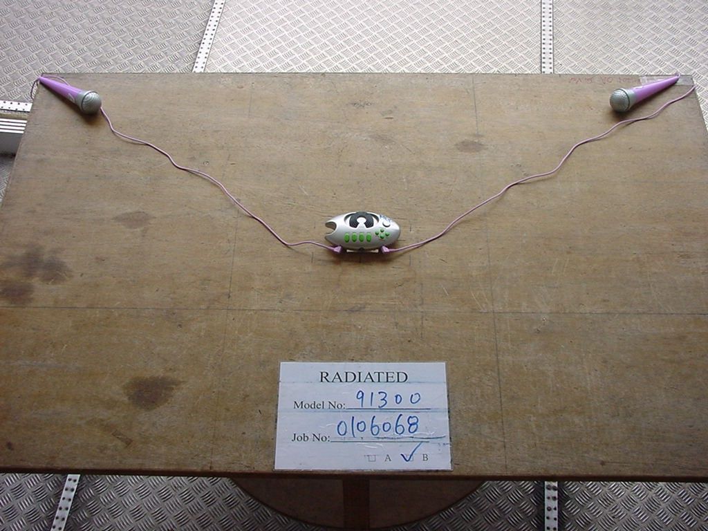
• The test results reported in this report shall refer only to the sample actually tested and shall not refer or be deemed to refer to bulk from which such a sample may be said to have been obtained. • This report shall not be reproduced except in full without prior authorization from Intertek Testing Services Hong Kong Limited FCC ID : NYX-91300 Trendmasters Inc. Application For Certification (FCC ID: NYX-91300) Transmitter, Model : 91300 We hereby certify that the sample of the above item is considered to comply with the requirements of FCC Part 15, Subpart C for Intentional Radiator, mention 47 CFR [10-1-99 edition] WO# 0106068 WN/at June 20, 2001 INTERTEK TESTING SERVICES FCC ID: NYX-91300 i LIST OF EXHIBITS INTRODUCTION EXHIBIT 1:General Description EXHIBIT 2:System Test Configuration EXHIBIT 3:Emission Results EXHIBIT 4:Equipment Photographs EXHIBIT 5:Product Labelling EXHIBIT 6:Technical Specifications EXHIBIT 7:Instruction Manual EXHIBIT 8:Miscellaneous Information INTERTEK TESTING SERVICES FCC ID: NYX-91300 ii MEASUREMENT/TECHNICAL REPORT Trendmasters Inc. - MODEL: 91300 FCC ID: NYX-91300 June 20, 2001 This report concerns (check one:)Original Grant X Class II Change Equipment Type: Low Power Transmitter (example: computer, printer, modem, etc.) Deferred grant requested per 47 CFR 0.457(d)(1)(ii)?Yes No X If yes, defer until: date Company Name agrees to notify the Commission by: date of the intended date of announcement of the product so that the grant can be issued on that date. Transition Rules Request per 15.37?Yes No X If no, assumed Part 15, Subpart C for intentional radiator Report prepared by:Wilbur Ng Intertek Testing Services 2/F., Garment Center, 576, Castle Peak Road, HONG KONG Phone:852-2173-8502 Fax:852-2742-9149 INTERTEK TESTING SERVICES FCC ID: NYX-91300 iii Table of Contents 1.0 General Description.......................................................................................................................2 1.1 Product Description...................................................................................................................2 1.2 Related Submittal(s) Grants.....................................................................................................2 1.3 Test Methodology......................................................................................................................3 1.4 Test Facility...............................................................................................................................3 2.0 System Test Configuration............................................................................................................5 2.1 Justification...............................................................................................................................5 2.2 EUT Exercising Software..........................................................................................................5 2.3 Special Accessories....................................................................................................................5 2.4 Equipment Modification...........................................................................................................6 2.5 Support Equipment List and Description.................................................................................6 3.0 Emission Results............................................................................................................................8 3.1 Field Strength Calculation........................................................................................................9 3.1 Field Strength Calculation (cont’d).........................................................................................10 3.2 Radiated Emission Configuration Photograph......................................................................11 3.3 Radiated Emission Data.........................................................................................................12 4.0 Equipment Photographs.............................................................................................................15 5.0 Product Labelling.........................................................................................................................17 6.0 Technical Specifications..............................................................................................................19 7.0 Instruction Manual......................................................................................................................21 8.0 Miscellaneous Information.........................................................................................................23 8.1 Measured Bandwidth..............................................................................................................24 8.2 Emissions Test Procedures.....................................................................................................25 8.2 Emissions Test Procedures (cont'd)........................................................................................26 INTERTEK TESTING SERVICES FCC ID: NYX-91300 iv List of attached file Exhibit typeFile Descriptionfilename Test ReportTest Reportreport.doc Operation DescriptionTechnical Descriptiondescri.pdf Test Setup PhotoRadiated Emissionradiated1.jpg to radiated2.jpg Test ReportBandwidth Plotbw.pdf External PhotoExternal Photoophoto1.jpg to ophoto2.jpg Internal PhotoInternal Photoiphoto1.jpg to iphoto5.jpg Block DiagramBlock Diagramblock.pdf SchematicsCircuit Diagramcircuit.pdf ID Label/LocationLabel Artwork and Locationlabel.pdf User ManualUser Manualmanual.pdf INTERTEK TESTING SERVICES FCC ID: NYX-91300 1 EXHIBIT 1 GENERAL DESCRIPTION INTERTEK TESTING SERVICES FCC ID: NYX-91300 2 1.0General Description 1.1Product Description The equipment under test (EUT) is a transmitter for Radio Microphone operating at 105 MHz which is controlled by a L.C. Oscillator. The EUT is powered by…
Text truncated - open the document above for the full version.
Contact Information
Applicant
Eddie Chan(Sr. Engineer)
852 2367-8892Fax: 852 2366-0789
Technical Contact
Intertek Testing Services Hong Kong Ltd.Wilbur Ng
[email protected]852-2173-8502
2/F., Garment Centre, · Kowloon · Hong Kong
Non-Technical Contact
Intertek Testing Services Hong Kong Ltd.Wilbur Ng
[email protected]852-2173-8502
Test Firm
Intertek Testing Services Hong KongBilly Chow
Technical Specifications
| # | Rule Parts | Frequency Range | Power Output |
|---|---|---|---|
| 1 | 15C | 105 MHz - 105 MHz | - |
Other Applications from Trendmasters Inc.

NYX-32135
Jun 19, 2001Walkie Talkie
Equipment Class
DXT - Part 15 Low Power Transceiver, Rx Verified
NYX-32138
Apr 16, 2001Toy walkie talkie 49.86MHz
Equipment Class
DXX - Part 15 Low Power Communication Device Transmitter
NYX-32139
Apr 16, 2001One way toy walkie talkie
Equipment Class
DXX - Part 15 Low Power Communication Device Transmitter
NYX-31268-27
Jul 30, 1998R\c Toy Transmitter
Equipment Class
DXX - Part 15 Low Power Communication Device Transmitter