NZ4GNT-FA1500-28Point-to-Point digital radio
Ceragon Networks Ltd.
Click to zoom
Application Details
- Equipment Class
- TNB - Licensed Non-Broadcast Station Transmitter
- Date of Grant
- Jul 02, 2000
- Application Purpose
- Original Equipment
- Date of Application
- Apr 15, 2000
- Equipment Note
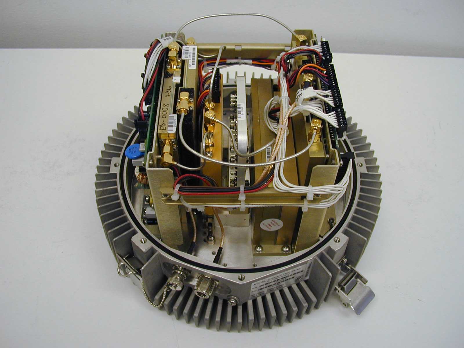
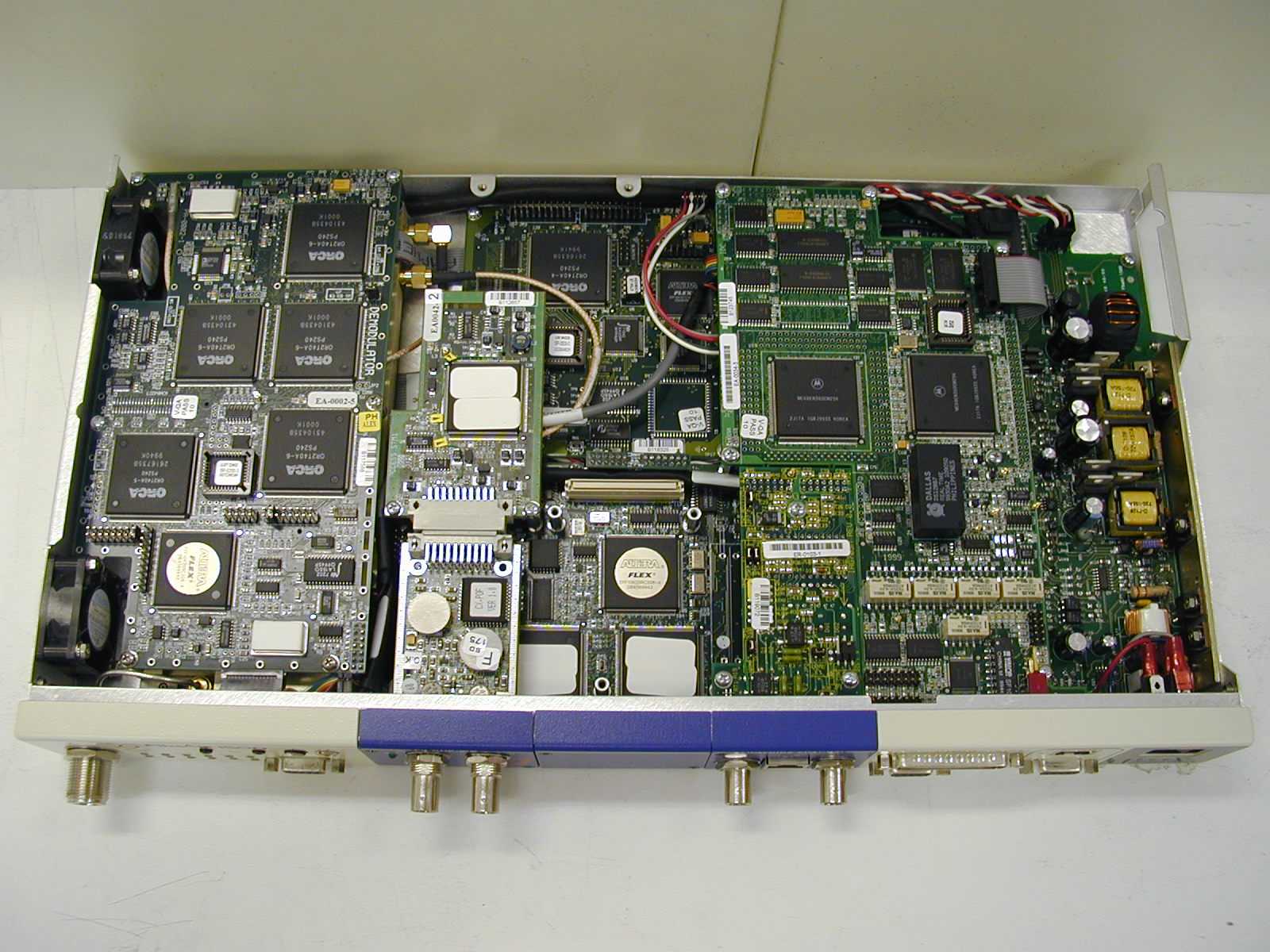
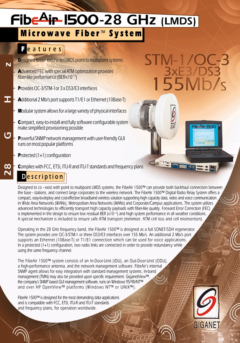
- Point-to-Point digital radio
- Frequency Range
- 29125.00000000 - 29225.00000000
- Company
- Ceragon Networks Ltd.
- Country
- Israel
Documents & Files
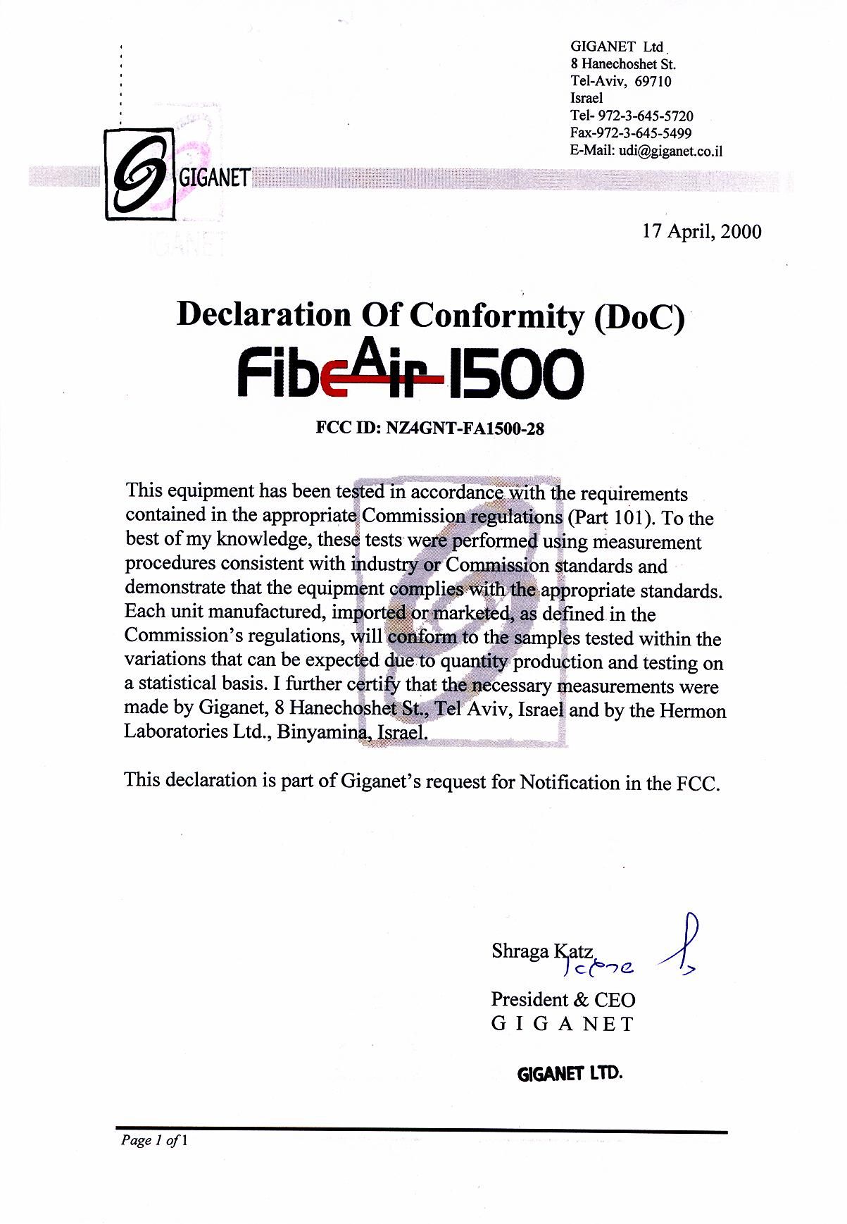
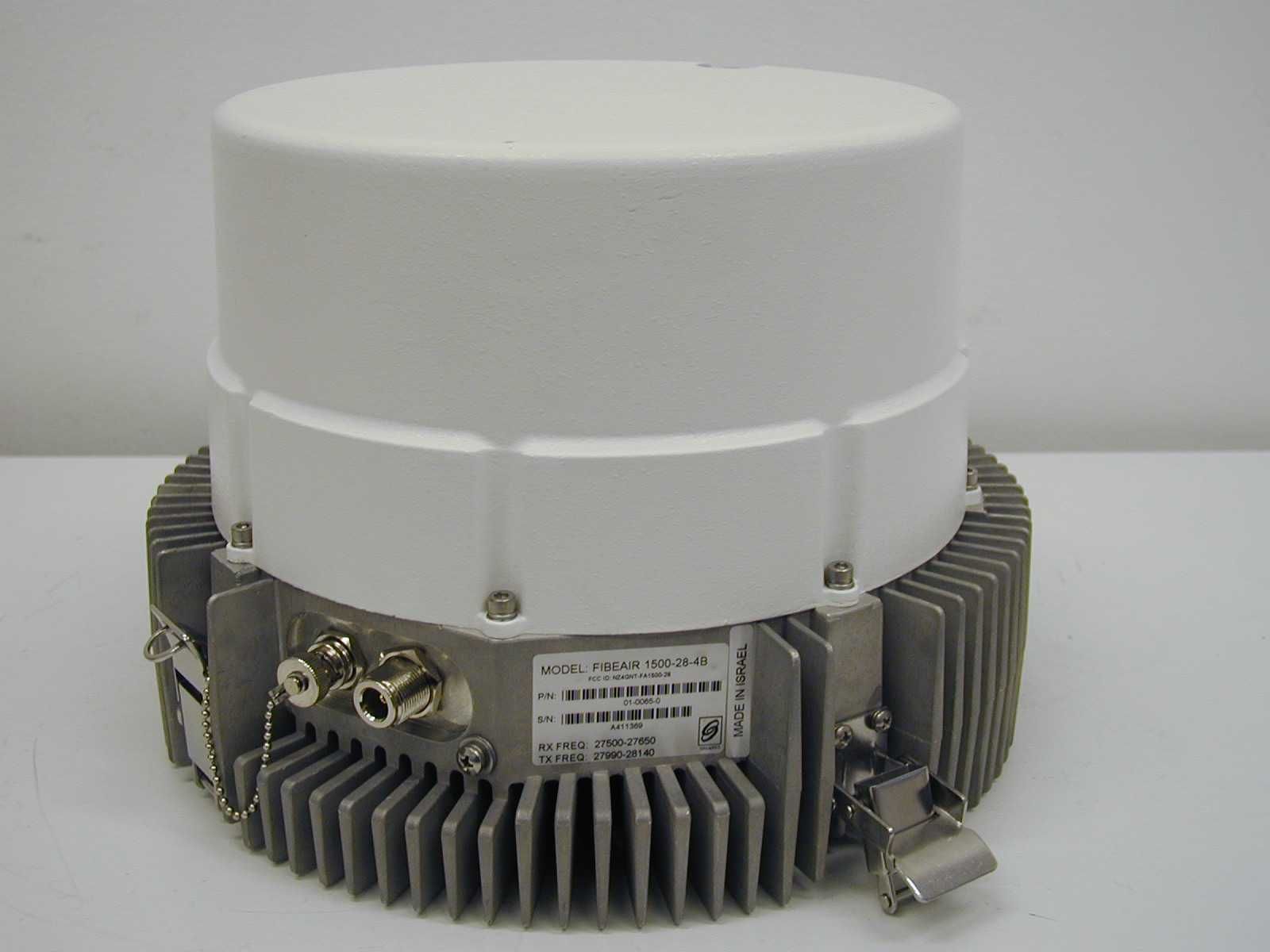
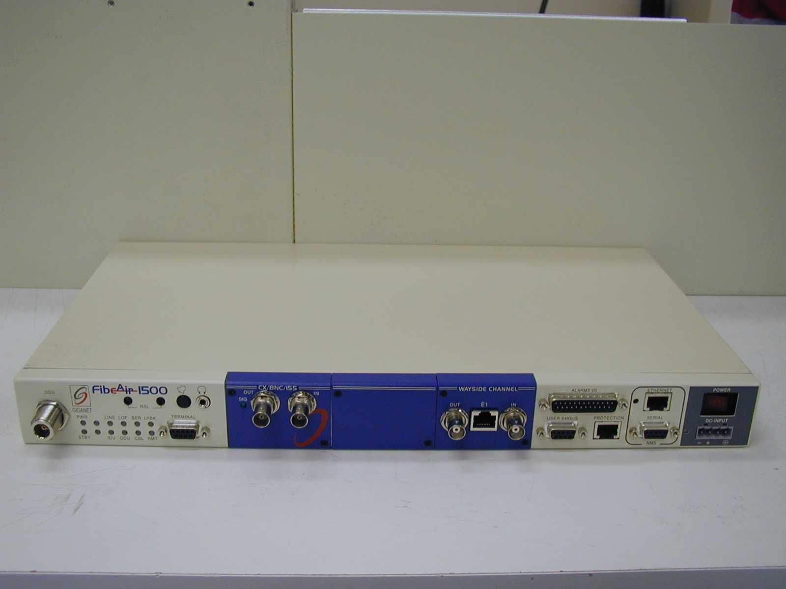
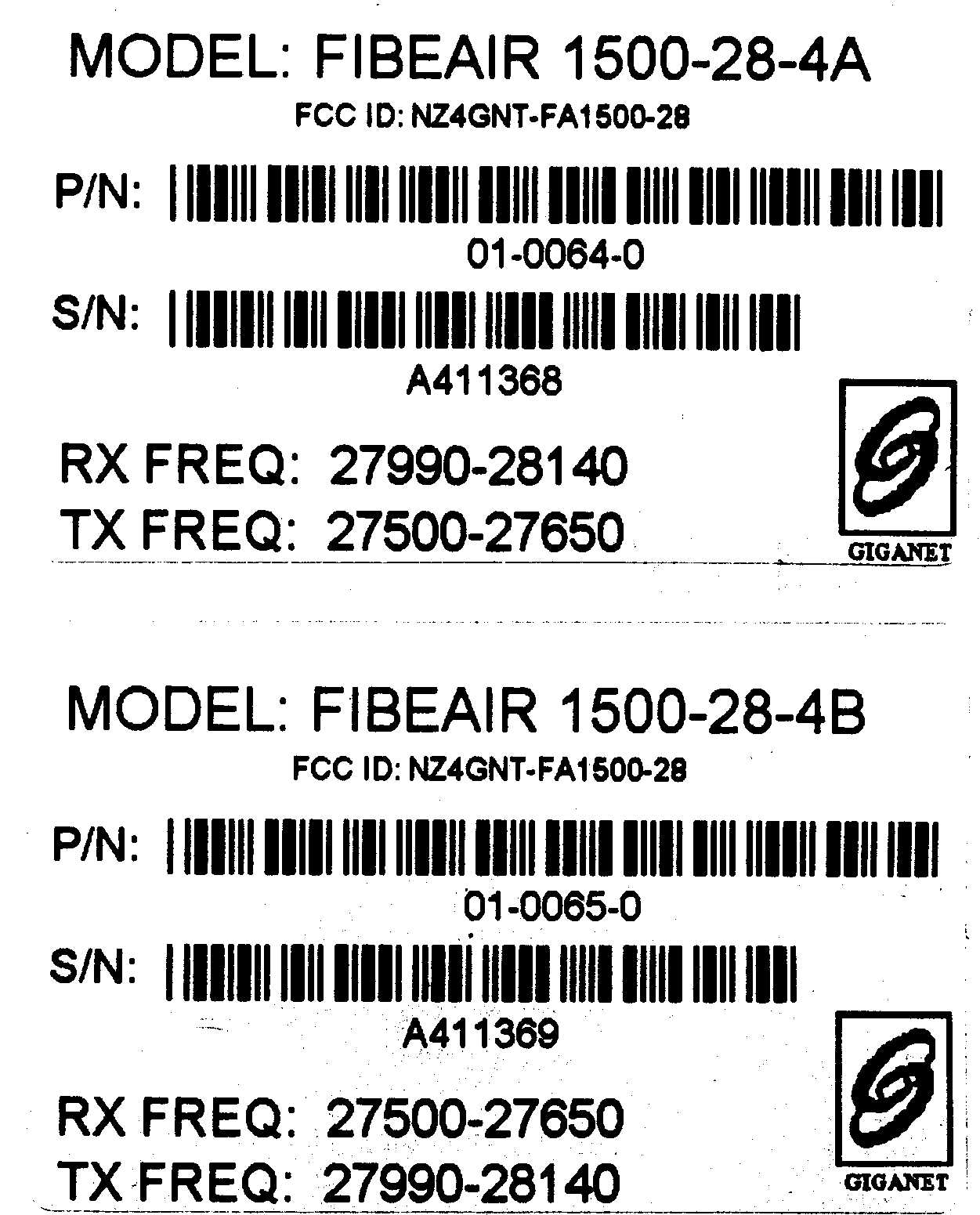
Document Text
Text extracted from the exhibit documents filed with the FCC. Open a document above to read the original.
Users Manual
Revision 2.0Prerequisites 4-1 4.1. Prerequisites The system setup and configuration follows the system installation, initial testing and antenna alignment as described in chapter 3. 4.2. The Setup Procedure The FibeAir 1500 setup procedure consists of the following operations : 1. Defining general settings — Setting local device communication parameters — Setting SNMP parameters 2. Defining system configuration parameters — Setting transmit frequency — Setting output power levels 3. Defining system information — Date — Time — Name — Contacts — Location 4. Defining SONET/SDH configuration parameters 5. Defining management setup parameters — Defining manager list — Defining alarm groups — Setting external alarm inputs — Setting alarm outputs FibeAir 1500 Installation & Operation ManualChapter 4. System Setup 4-2The Setup ProcedureRevision 2.0 4.2.1. System Setup To start the FibeAir 1500 radio link configuration you first need to setup the Ethernet and PPP/SLIP IP addresses. Once you have defined these addresses, you will be able to configure the system using the GiganetView software. To set the addresses, perform the following operations: 1. Connect the RS-232 port of your computer to the RS-232 (9-PIN) port on the indoor unit front panel. This port is labeled “Terminal” and is located near the front panel LEDs. 2. Connect to the standard Windows HyperTerminal at 19,200 bits per second. 3. After you are connected, press Enter. The login menu appears. Figure 4-1 FibeAir 1500 Terminal - Login Screen 4. Type giganet as the password. The main menu displays. Figure 4-2 FibeAir 1500 Terminal - Main Configuration Menu Chapter 4. System Setup FibeAir 1500 Installation & Operation Manual Revision 2.0The Setup Procedure 4-3 For a more detailed description of the HyperTerminal configuration procedure, refer to the following section 4.2.2 – “Connecting to the HyperTerminal.” 4.2.2. Connecting to the HyperTerminal Setting Up the HyperTerminal Connection To set up the HyperTerminal connection, perform the following operations: 1. Connect the RS232 port of your computer to the Terminal port of the IDU. 2. Select Start Ω Programs Ω Accessories Ω Communication Ω HyperTerminal. 3. Double-click the HyperTerminal application icon. 4. In the Connection Description box, enter the name Terminal and click OK. 5. In the Connect Using field (in the Phone Number box) select Direct to Com 1 and click OK. 6. In the Port Settings tab (Com 1 Properties box) configure the following settings: — Bits per second – 19,200 — Data bits - 8 — Parity - None — Stop bits - 1 — Flow control - Hardware 7. Click OK. 8. End the HyperTerminal connection. Connecting to the Terminal To connect to the terminal, perform the following operations: 1. Connect the RS232 port of your computer to the Terminal port of the IDU. 2. Select Start Ω Programs Ω Accessories Ω HyperTerminal. 3. Double-click the Terminal connection icon. The HyperTerminal screen opens. 4. Enter the password giganet and press Enter. The Main Configuration Menu appears. Note: The Terminal screens are depicted here as black text on a white background for ease of reading. The original screens are white text on black background. FibeAir 1500 Installation & Operation ManualChapter 4. System Setup 4-4The Setup ProcedureRevision 2.0 4.2.3. Quick Setup To perform quick setup, carry out the following operations: 1. From the Main Configuration Menu, select 1 – Quick Setup and press Enter. The Quick Setup menu appears. Note: Quick Setup is the recommended option if you are not familiar with the system. More advanced users may use the Full Configuration menu. Figure 4-3 FibeAir 1500 Terminal - Quick Setup Menu 2. Accept or change each parameter value. Press Enter to accept the existing value or type in the new value in the space provided. — Ethernet IP address: The FibeAir 1500 Ethernet port IP address you wish to use. — Ethernet IP Mask: Your network IP sub-net address. — Serial IP address: The FibeAir 1500 Serial port IP address you wish to use. — Serial IP Mask: Your network IP sub-net address. — Default Router IP address: The FibeAir’s default router address. — Read community: The community password for read only devices. — Write community: The community password for read/write devices. — Trap option: “0” – sending standard trap, “1” – sending trap with unit serial I.D. The recommended option is “0”. — Serial Type: Defines the serial communication type, PPP or SLIP. — Serial Baud Rate: Serial communication port baud rate. — Dial-Out Phone Number: The phone number to be dialed by the indoor unit. Chapter 4. System Setup FibeAir 1500 Installation & Operation Manual Revision 2.0The Setup Procedure 4-5 The PPP protocol adds security to the communication and therefore additional parameters need to be configured in the system: — Authentication Protocol Type: 0 – None 1 – PAP (without encryption) 2 – CHAP (with encryption) — Authentication Mode: 2 – GUEST. The IDU gives the user name and password to the network manager. 3 – HOST. The IDU receives the user and password from the network manager and validates them. 4 – DYNAMIC. When the IDU receives a phone call, it acts as a HOST. If it initiates a call to the network manger (SNMP trap) it will act like a GUEST. In case of a direct connection (without a dialup modem) it acts as a HOST. — Dial-In Authentication User Name: Enter the user name that is used to validate a user dialing in to the indoor unit. — Dial-In Authentication Password: Enter the password that is used to validate a user dialing in to the indoor unit. — Dial-Out Authentication User Name: Enter the user name that will be used by the IDU to gain access to the remote manager. — Dial-Out Authentication User Password: Enter the Password that will be used by the IDU to gain access to the remote manager. — Transmit Frequency: The frequency Channel number you wish to use. — Transmit Power: Power output level. FibeAir 1500 Installation & Operation ManualChapter 4. System Setup 4-6T…
Text truncated - open the document above for the full version.
Users Manual
Revision 2.0General5-1 5.1. General This chapter explains in detail how to operate the GiganetView management software and operate, configure and monitor the FibeAir 1500. 5.2. Logging In To log into the GiganetView management software follow these steps: 1. Select Start Ω Program Ω GiganetView. The Login window is displayed. Figure 5-1 Login window Chapter 5. Operation FibeAir 1500 Installation & Operation Manual 5-2The Work Area WindowRevision 2.0 To log in, enter your password and click OK. There are two types of passwords, each with a different security level and authorized activities: Read only – System Operator permitted to perform monitoring activities only. Read/write - Super User permitted to change system configuration, System Administrator parameters and perform monitoring activities. The initial factory-set read/write password is giganet. After logging in, the Work Area and Physical View windows are displayed (see section 3.3 and 3.4 for details). 5.3. The Work Area Window The Work Area window is your starting point for all operations. Below is a description of the menus, toolbars and other features of the Work Area window. Figure 5-2 Work Area Window FibeAir 1500 Installation & Operation ManualChapter 5. Operation Revision 2.0The Work Area Window5-3 5.3.1. Title Bar The title bar of the Work Area window displays the following information: Figure 5-3 Title Bar Note that the "name of terminal" is user-defined via the General Information window (Configuration Ω System Information). See section 4.4 for details. Closing the Working Area window by clicking on the "close window" button, on the right side of the title bar is tantamount to logging out of the system. 5.3.2. Menu Bar The menu bar of the Work Area window allows you to select options from six menus. Figure 5-4 Menu Bar Below is a list of the various menus and the options they offer: Figure 5-5 File Menu Figure 5-6 Configurations Menu FibeAir Logo Name of terminal Name of window Minimize window Close window (Log off) Chapter 5. Operation FibeAir 1500 Installation & Operation Manual 5-4The Work Area WindowRevision 2.0 Figure 5-7 Alarm Menu Figure 5-8 Statistics Menu Figure 5-9 Maintenance Menu 5.3.3. Toolbars The Work Area window has four toolbars: n a general toolbar horizontally laid out directly below the menu bar n an ODU toolbar below the File menu option n an IDU toolbar n a Sonet/SDH toolbar. FibeAir 1500 Installation & Operation ManualChapter 5. Operation Revision 2.0The Work Area Window5-5 General Toolbar KeyExplanation General Information − view and define system parameters such as link definitions, contacts, system up time and IDU and ODU serial numbers. System Configuration − view and define general settings such as Local Device Communications, managers list and the alarms reported to them. Set Frequency − define the frequency of the local and remote units. Maintenance − perform loopbacks and insert alarm signals. Local RSL Monitoring − attain a graph of the local received signal level. Remote RSL Monitoring − attain a graph of the remote received signal level. KeyExplanation Alarm Status − view the current alarm status. Alarm Log File − view the log file. Help − starts the online help system. ODU Toolbar ODU Configuration − view and set up the radio link parameters. Local RSL Statistics Monitoring − view local received signal level data. Remote RSL Statistics Monitoring − view remote received signal level data. IDU Toolbar Local Unit Configuration − define Local IDU parameters. Remote Unit Configuration − define Remote IDU parameters. Chapter 5. Operation FibeAir 1500 Installation & Operation Manual 5-6Physical ViewRevision 2.0 Sonet/SDH Toolbar Sonet/SDH Configuration − view and configure Sonet/SDH parameters. Local Sonet/SDH Performance Monitoring − view Sonet/SDH performance data of the Local unit. Remote Sonet/SDH Performance Monitoring − view Sonet/SDH performance data of the Remote unit. 5.4. Physical View The Physical View window is constantly displayed after logging into the FibeAir 1500 management program. It provides a real-time virtual display of the IDU front panel. This window may be closed and reopened at any time. The window is reopened by selecting File ΩPhysical View on the Work Area window. Figure 5-10 Physical View Window Place the pointer over any item in the window and hold it there to view a ToolTip description of the item. Also, the status bar on the bottom of the window constantly displays the name of the currently selected item (e.g., LED Alarms, Power Switch). The display of the LEDs on the Physical View window indicates the actual real-time status of the LEDs on the front panel of the IDU. Note that there is a slight delay between the changes on the front panel and the time that they are displayed on the Physical View window. The LEDs on the front panel indicate the status of a number of important factors. For the most part, the following rule applies: Green indicates a good state (OK), Yellow indicates a warning, and Red indicates a major alarm or a severe malfunction. See Table 3-1, below, for details. FibeAir 1500 Installation & Operation ManualChapter 5. Operation Revision 2.0Physical View5-7 Table 5-1IDU LED Alarms LED NameColorDescription RedYellowGreen* “Power” XXRed - Problem with power supplies, system not functional. “Future Use” “Line” XX XRed - No input to main channel / High BER Yellow – JO mismatch. “Loss of Frame” XX Red – Radio did not recognize information frame (radio link problem/radio LOF). “BER”XX X Red – radio BER higher than radio excessive error threshold definition (please refer to Sonet/SDH configuration screen). Yellow – radio BER higher then radio signal degrade threshold definition (please refer to Sonet/SDH configuration screen). “Loopback”XXRed – Loopback is active. “Stand By” XX Yellow – Protected configuration: This unit is currently passive or Tx mute applied. “Future Use” “IDU” XX X Red – Modem unlocked. Yellow – High temperature / Fan problem. “ODU…
Text truncated - open the document above for the full version.
Users Manual
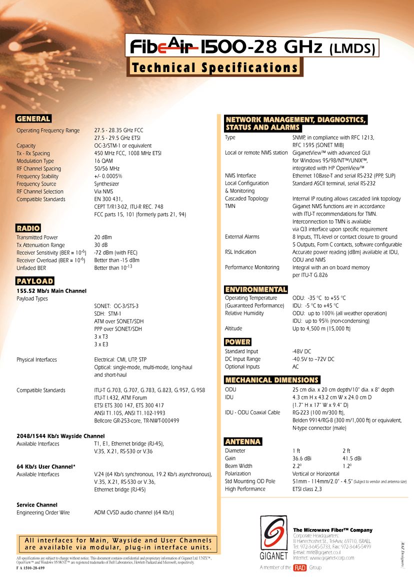
Revision 2.0 System Block Diagram2-1 2.1. System Block Diagram This chapter presents FibeAir 1500 basic principles of operation. The FibeAir 1500 design concept is based on universal radio architecture. A radio link consists of two FibeAir 1500 terminals. Each terminal includes three major LRU’s, IDU, ODU and the Antenna. A single cable, carrying communications and DC power, interconnects the IDU with the ODU. Figure 2-1 presents FibeAir 1500 main blocks and modules. Figure 2-1 FibeAir 1500 System Block Diagram Chapter 2. Theory of Operation FibeAir 1500 Installation & Operation Manual 2-2In Door Unit (IDU) Revision 2.0 2.2. In Door Unit (IDU) The IDU is a compact, 17” wide, 1U-high unit, mount compatible for both ETSI and ANSI standard racks. The IDU modulates/demodulates the 155Mbps Sonet/SDH payloads, manages local and remote units, provides I/O line alarms, and provides interfaces for 1.544/2.048 Mbps Wayside channel, 64Kbps User channel and 64Kbps Order Wire channel. The IDU also interfaces a Local Maintenance Terminal or Network Management System. In addition, status alarms and indicators are provided on the front panel. The IDU major modules: n Multiplexer n Modem n Manager Card n Cable Interface n Power Supply 2.2.1. Multiplexer The Mux module functions as a Sonet/SDH Regenerator. On the line side it interfaces the OC-3/STM-1 stream, and on the radio side the Modem module. As a regenerator, the MUX either terminates or regenerates the OC-3/STM-1 RSOH. In one direction, the OC-3/STM-1 stream, interfacing through the MUX’s Rx line input terminates and the resulting stream is transmitted to the Modulator in the Modem module. In the opposite direction, the stream coming from the Modem’s Demodulator, undergoes OC-3/STM-1 Regeneration in the MUX, and transmitted through the MUX’s Tx line output. In addition, the MUX module uses the OC-3/STM-1 SOH bytes to support other services: 1.544/2.048 Mbps Wayside channel and management, 64 Kbps User Channel and Order Wire channel. The MUX module may be configured via software for transparency of most of the SOH bytes for maximum system transparency and non-intervention, at the cost of reduced functionality and services. The multiplexer module enables to integrate different interfaces and services into the SDH payload to converge Datacom and Telecom applications. FibeAir 1500 Installation & Operation ManualChapter 2. Theory of Operation Revision 2.0 In Door Unit (IDU)2-3 2.2.2. MODEM The FibeAir 1500 is equipped with a 16-states QAM Modem. The modem delivers a 155 Mb/s payload in 50/56 MHz channel bandwidth in compliance with FCC/ETSI standards. The Modem is equipped with Digital Signal Processing functions as follows: n Digital IF - I/Q modulator/demodulator whose functions are: ⇒ Conversion of the modulated signal to/from the IF frequency. ⇒ Automatic level equalization on the signal from ODU. ⇒ Protection against overloads. n Timing recovery techniques employing digital tracking loop. n FEC ensures unfaded BER lower than 10 -13 . The following figure illustrates a measured 16 QAM constellation. Figure 2-2 16 QAM Constellation Chapter 2. Theory of Operation FibeAir 1500 Installation & Operation Manual 2-4In Door Unit (IDU) Revision 2.0 2.2.3. Manager Module The Manager module controls and manages all system’s modules, local and remote units. The Manager module also supports the user interface through Ethernet or PPP/SLIP to the management station, and an ASCII terminal port. A local or dumb terminal can be used for basic configuration and performance monitoring. Other features include: n Log file. n Remote software and firmware download (upgrades can be downloaded from local to remote). n Performance monitoring. 2.2.4. Cable Interfaces A single coaxial cable connects the IDU to the ODU. This cable carries the following signals: n Transmit and receive modulated signals. n Transmit and receive control data and communications between the IDU manager and the ODU controller. n DC power from the IDU to the ODU. The system automatically issues an alarm if the cable is disconnected and provides protection against shorts. Furthermore, there is no need to measure and define the length and type of cable used since the system automatically compensates cable parameters. The following figure illustrates the signal direction through the coaxial cable. -48 VDC ODU TO IDU (CONTROL) IDU TO ODU (CONTROL) TX (PAYLOAD 155M) RX (PAYLOAD 155M) Figure 2-3 Signal Direction Through the Coaxial Cable FibeAir 1500 Installation & Operation ManualChapter 2. Theory of Operation Revision 2.0 Out Door Unit (ODU)2-5 2.2.5. Power Supplies The power supply features: n Standard Input : -48VDC n DC input range : -40.5VDC to –72VDC n DC/DC converter. n Reverse polarity protection. n Over-voltage and over-current protection. n Detection of IDU-ODU cable alarms (i.e. cable open, cable short). The ODU receives its DC power from the IDU. The PWR LED on the front panel of the IDU continuously lights to indicate the existence of input voltage. 2.3. Out Door Unit (ODU) The ODU is designed to be fastened to the antenna using four latches. The antenna is mounted on a standard mounting pole. The ODU is enclosed in a compact, weather proof enclosure and connects to the IDU via a single coaxial cable that can extend up to 300m (1000 ft). The ODU major modules: n T/R Module – A high sensitivity RF circuitry with full band frequency tuning range. n Controller – Controls the ODU and provides ODU status signals, and accurate received signal level (RSL) reading (in dBm). n Cable Combiner – Detailed in paragraph 2.2.4. n Power Supply - Detailed in paragraph 2.2.5. Figure 2-4 ODU Mounted on the Antenna Latches Chapter 2. Theory of Operation FibeAir 1500 Installation & Operation Manual 2-6System Specifications Revision 2.0 2.4. System Specifications 2.4.1. General 18 GHz 23 GHz26 GHz28 GHz38 GHz StandardsFCC/ETSIFCC/ETSIETSI FCC/ETSI/ Canada FCC/ETSI Operating frequency range 17.7 - 19.7 GHz 21.2 - 23.…
Text truncated - open the document above for the full version.
Users Manual
Revision 2.0General3-1 3.1. General This chapter explains how to install and set up the FibeAir 1500 system. For best results, perform all operations in the sequence in which they are presented in this chapter. 3.2. Unpacking Equipment The FibeAir 1500 is shipped in 5 crates. Upon delivery, make sure that the following items are included: n Two indoor units and accessories n Two outdoor units n Two antennas and pole mounts n One user manual n One management software (CD). Unpack the contents and check for damaged or missing parts. Should there be any parts that are damaged or missing, contact Giganet’s local distributor. 3.3. Site Requirements The first and most important consideration when choosing a prospective site for the ODU is that the point can provide an acceptable “line of sight” with the opposing ODU. A site with a clear, unobstructed view is required. When considering a site, it is important to check for current and future obstacles. Possible future obstacles are: trees, new buildings, window cleaners on the roof, snow that may accumulate in front of the antenna, etc. The site should be accessible to certified personnel only. As with any type of construction, a local permit may be required before installing an antenna. It is the owner’s responsibility to obtain any and all permits. Chapter 3. Installation FibeAir 1500 Installation & Operation Manual 3-2Before Installing the ODURevision 2.0 3.4. Before Installing the ODU DANGER WATCH FOR WIRES! Installation of this product near power lines is dangerous. For your own safety, follow these important safety rules. n Perform as many assembly functions as possible on the ground. n Watch out for overhead power lines. Check the distance to the power lines before starting installation. n Do not use metal ladders. n If you start to drop the antenna or mast assembly, move away from it and let it fall. n If any part of the antenna or mast assembly comes in contact with a power line, call your local power company. DO NOT TRY TO REMOVE IT YOURSELF! They will remove it safely. n Make sure that the mast assembly is properly grounded. WARNING! Assembling antennas on windy days can be dangerous. Because of the antenna surface, even slight winds create strong forces. Be prepared to safely handle these forces at unexpected moments. Giganet Ltd. is not responsible or liable for damage or injury resulting from antenna installation. 3.5. Required Components and Equipment 3.5.1. Required System Components The following FibeAir 1500 components are needed to install one radio link: n Antenna mount and accessories n Antenna n ODU n Cable n Headset n BNC headset adaptor n BNC DVM adaptor. FibeAir 1500 Installation & Operation ManualChapter 3. Installation Revision 2.0Required Components and Equipment3-3 3.5.2. Required Tools The following tools and equipment are needed to install an ODU: n 4 x N-type connectors (according to cable type) n Coaxial cable n Insulation tape n Ratchet wrench (3/8” Drive) n 10mm nut driver n 13mm socket (3/8” Drive) n 13mm open/box end wrench n Phillips screwdriver n Sharp cutting knife n Compass (optional) n Torque wrench n Digital voltmeter n Giganet optical view finder (optional) 3.5.3. Local Management PC Hardware Requirements Before you install the GiganetView software, verify that your PC has the minimum requirements as follows: ProcessorPentium (200 MHz minimum) Memory (RAM)32 MB minimum Operating SystemWindows 95/98/NT Display Monitor800 x 600 minimum, 16,384 colors maximum Keyboard Mouse Serial PortRS-232 Chapter 3. Installation FibeAir 1500 Installation & Operation Manual 3-4Suggested Pole InstallationRevision 2.0 3.6. Suggested Pole Installation The antenna can be installed on a ground tube, roof, or wall mount. The ground tube or roof/wall mount should be assembled and in place before installing the antenna mount. Figure 3-1 Calculating Required Pipe Diameters Use the following table to determine the pipe diameters: Table 3-1Wind Loading Antenna Size1 ft. (30 cm) 2 - 2 1 / 2 ft. (60 - 75 cm) 4 ft.(120 cm) Minimum Pipe Diameter50 mm65 mm115 mm Wind Velocity200 km/h200 km/h200 km/h F AT, max. [N]3039292821 F ST, max. [N]1504601398 M T, max. [Nm]47283894 After determining the pole size, verify that you have the required bolt for the antenna mount. Table 3-2Required Bolt size Pipe Diameter [mm]Bolt size [mm] 48 - 5151 52 - 8989 90 - 115115 FibeAir 1500 Installation & Operation ManualChapter 3. Installation Revision 2.0Flow of Operations3-5 3.7. Flow of Operations The installation and setup procedure for the FibeAir 1500 consists of the following operations (to be performed in the order listed below): GiganetView Management Software: n Installing the Management Software n Installing a PPP/SLIP Driver n Setting the Baud Rate IDU: n Installing the IDU n Turning IDU On n Connecting to a PPP/SLIP or Ethernet Port n Setting the IP addresses n Setting Local Tx Frequency Channel n Activating Engineering Order Wire (EOW) n Setting Antenna Diameter and Distance n Determining the Expected Signal Level ODU: n Installing the antenna assembly — Azimuth adjustment — Elevation adjustment n Initial antenna alignment − using a compass, Giganet’s optical view finder and headset. n Alignment − checking actual receive level n Performing an Initial Check n Verifying Installation. Chapter 3. Installation FibeAir 1500 Installation & Operation Manual 3-6Installing the IDU - Rack Mount AssemblyRevision 2.0 3.8. Installing the IDU - Rack Mount Assembly The IDU may be installed in a 19" rack (1U) using the rack mount kit. The mount braces are attached to each side of the IDU using the three holes on each side. To attach the rack mount to the IDU follow these steps: Figure 3-2 Rack Mount Assembly 1. Attach mount braces to each side of the IDU, and using the screws supplied attach them to the holes in the IDU side panel (see illustration). 2. Install the IDU unit in the 19” rack as shown in the lower part of the illustration. 3. To power on the unit…
Text truncated - open the document above for the full version.
Cover Letter(s)
To whom it may concern: On behalf of Giganet Ltd. We hereby wish the following document item to be kept confidential for the FCC certification filing of the 28GHz FibeAir-1500 point-to-point digital radio: ♦ Tune-up procedure and block diagram of the frequency sources and signal paths of the equipment. We are requesting in part to protect the technological advances and competitiveness of our product in the new broadband wireless technology industry and to fulfill the non-disclosure agreements we agreed to with various sub-assembly suppliers. On behalf of Giganet Ltd., we would like to thank you for your consideration on this matter. Please contact me should you have questions or require additional information. Sincerely, Udi Gordon Director of Systems Giganet Ltd. . . . . . . . . . GIGANET LTD 8 Hanechoshet St. Tel-Aviv, 69710 Israel Tel-972-3-645-5720 Fax-972-3-645-5499 E-Mail: [email protected]
Cover Letter(s)
Federal Communications Commission Equipment Approval Services P.O. Box 358315 Pittsburgh, PA 15251-5315 To whom it may concern: On behalf of Giganet Ltd. We hereby wish the following document item to be kept confidential for the FCC certification filing of the 28GHz FibeAir-1500 point-to-point digital radio: ♦ Block diagram of the frequency sources and signal paths of the equipment. We are requesting in part to protect the technological advances and competitiveness of our product in the new broadband wireless technology industry and to fulfill the non-disclosure agreements we agreed to with various sub-assembly suppliers. On behalf of Giganet Ltd., we would like to thank you for your consideration on this matter. Please contact me should you have questions or require additional information. Sincerely, Udi Gordon Director of Systems Giganet Ltd. . . . . . . . . . GIGANET LTD 8 Hanechoshet St. Tel-Aviv, 69710 Israel Tel-972-3-645-5720 Fax-972-3-645-5499 E-Mail: [email protected]
Cover Letter(s)
Federal Communications Commission Equipment Approval Services P.O. Box 358315 Pittsburgh, PA 15251-5315 To whom it may concern: On behalf of Giganet Ltd. We hereby wish the following document item to be kept confidential for the FCC certification filing of the 28GHz FibeAir-1500 point-to-point digital radio: ♦ Block diagram of the frequency sources and signal paths of the equipment. ♦ Schematic diagrams of the frequency sources and signal paths of the equipment. We are requesting in part to protect the technological advances and competitiveness of our product in the new broadband wireless technology industry and to fulfill the non-disclosure agreements we agreed to with various sub-assembly suppliers. On behalf of Giganet Ltd., we would like to thank you for your consideration on this matter. Please contact me should you have questions or require additional information. Sincerely, Udi Gordon Director of Systems Giganet Ltd. . . . . . . . . . GIGANET LTD 8 Hanechoshet St. Tel-Aviv, 69710 Israel Tel-972-3-645-5720 Fax-972-3-645-5499 E-Mail: [email protected]
Test Report
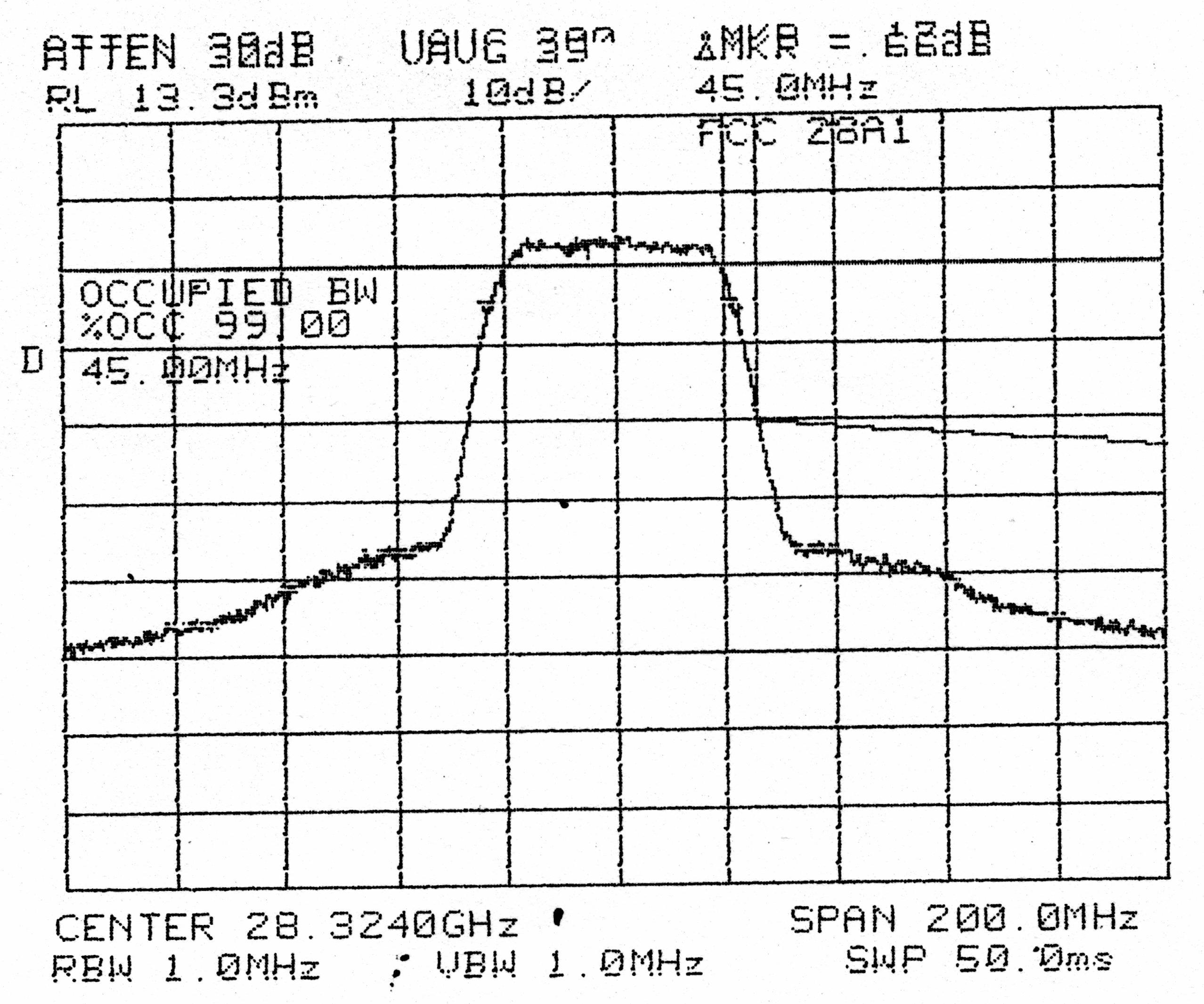
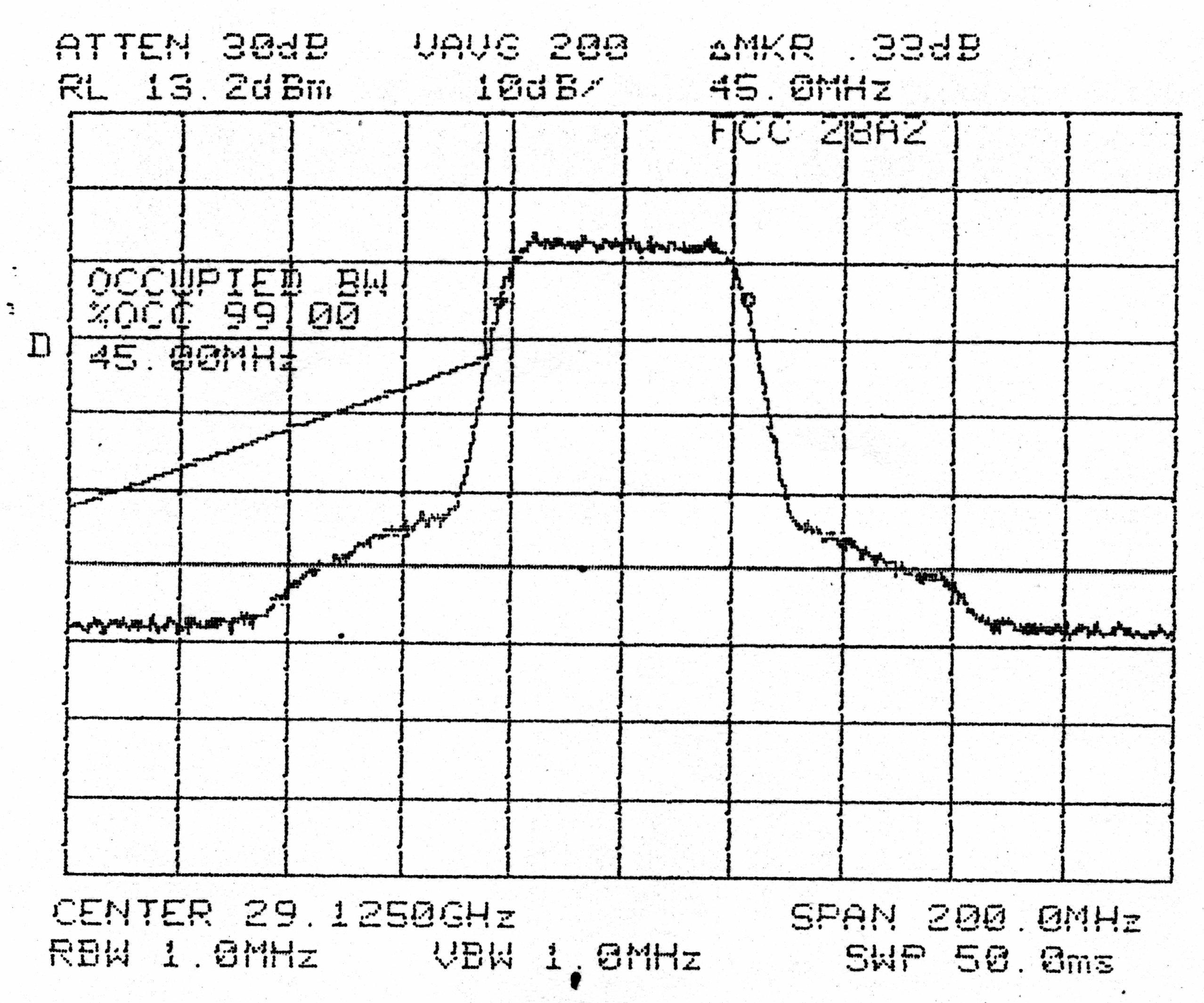
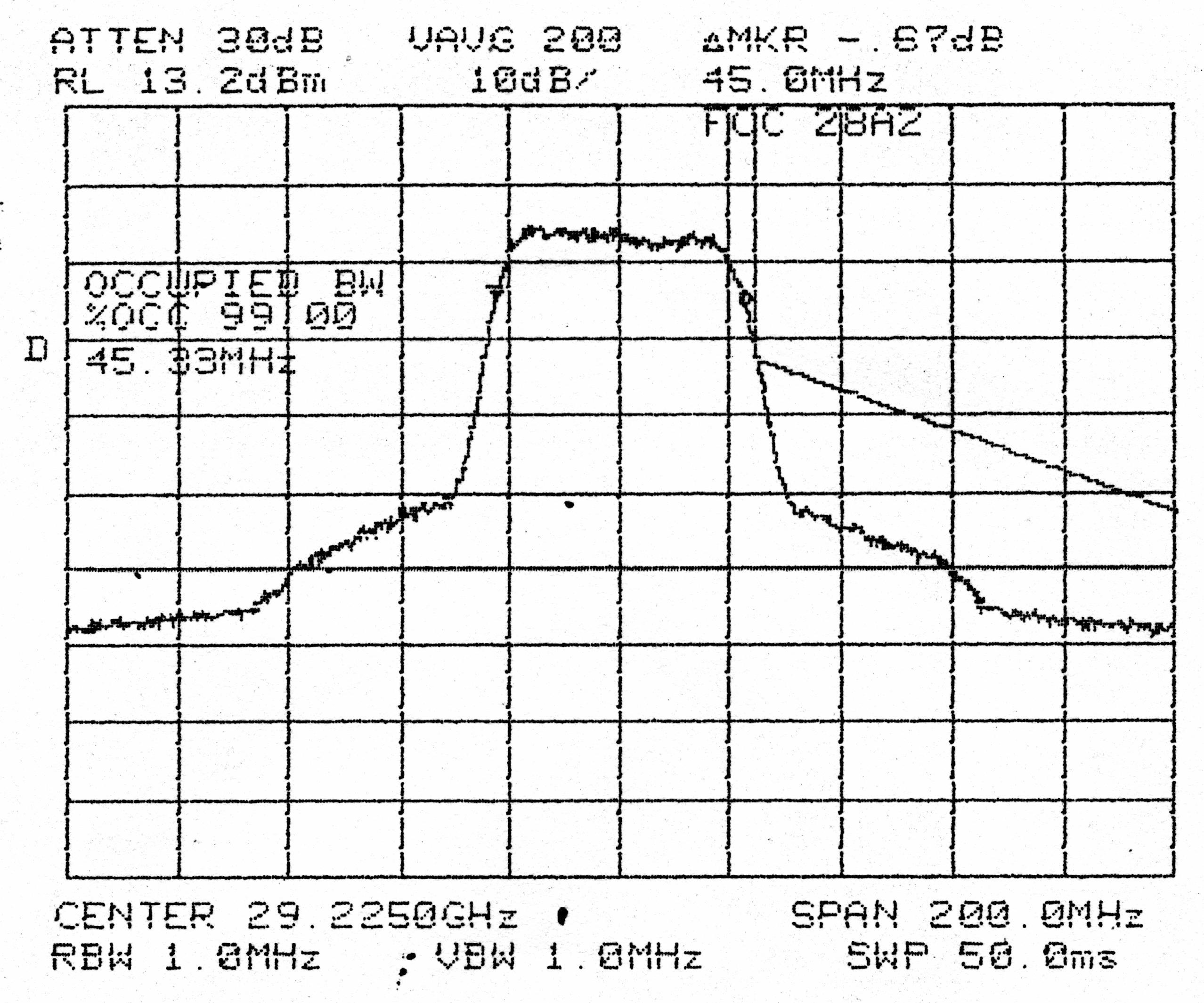
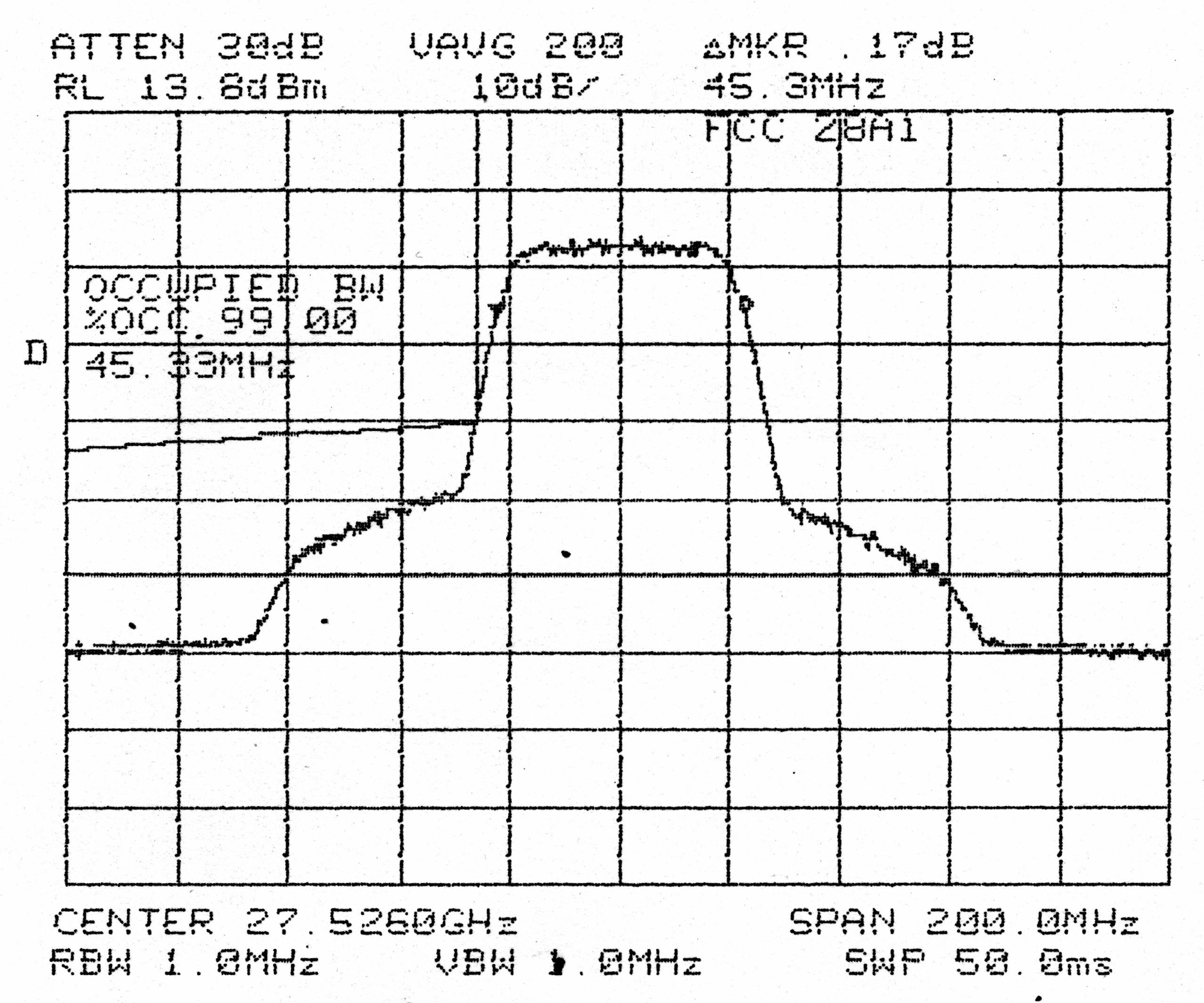
FibeAir 1500 TM Test Report CONTENTS Page 1 of 29Proprietary and Confidential 17 April, 2000 Test Report for FibeAir 1500 LMDS Band A Point-to-Point Radio To: FCC part 101 13 April, 2000 1 FibeAir 1500 TM Test Report CONTENTS Page 2 of 29Proprietary and Confidential 17 April, 2000 TABLE OF CONTENTS 1.TECHNICAL SUMMARY....................................................................................................................................... 3 2.TESTS REQUIRED .................................................................................................................................................. 4 3.MEASUREMENTS, EXAMINATIONS AND DERIVED RESULTS................................................................. 5 3.1.General Comments .............................................................................................................................................. 5 3.1.1.Test Results ................................................................................................................................................. 6 3.1.2.RF Power output.......................................................................................................................................... 6 3.1.3.RF spectrum Mask....................................................................................................................................... 7 3.1.4.Occupied Bandwidth ................................................................................................................................... 8 3.1.5.Spurious emissions at antenna terminals..................................................................................................... 9 3.1.6.Field strength of spurious radiation........................................................................................................... 10 3.1.7.FREQUENCY STABILITY...................................................................................................................... 12 4.SUMMARY OF TEST RESULTS......................................................................................................................... 13 5.TEST EQUIPMENT USED.................................................................................................................................... 14 6.GRAPHS................................................................................................................................................................... 16 FibeAir 1500 TM Test Report CONTENTS Page 3 of 29Proprietary and Confidential 17 April, 2000 1. Technical Summary Manufacturer:GIGANET Ltd. 8 Hanechoshet St. Tel Aviv Israel 69710 FCC IDNZ4GNT-FA1500-28 Number of units tested:One Equipment Category:Digital Microwave Fixed link Trade Name Of Equipment:FibeAir-1500 Manufacturer Type Designation:28-4A or 28-4B Type of Equipment:Transceiver Data Rate(s):155 Mbit/s Type of Modulation:16 QAM Type of Emission:50M0D7W Occupied Bandwidth (Inband: 99%,Outband:+0.5%,-0.5%): 48 MHz Rated Outpu…
Text truncated - open the document above for the full version.
Contact Information
Applicant
Sergey Shkolnik(Regulation Engineer)
Technical Specifications
| # | Rule Parts | Frequency Range | Power Output | Emission | Tolerance |
|---|---|---|---|---|---|
| 2 | 101 | 29.13 GHz - 29.23 GHz | 100.00 mW | 50M0D7W | 5 ppm |
Other Applications from Ceragon Networks Ltd.

NZ4CRN-FA1500-24
May 10, 2004Point to Point Radio
Equipment Class
DXX - Part 15 Low Power Communication Device Transmitter
NZ4GNT-FA1500-38
Jul 29, 1998FibeAir 1500/38
Equipment Class
TNB - Licensed Non-Broadcast Station Transmitter