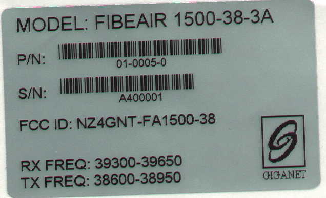
NZ4GNT-FA1500-38FibeAir 1500/38
Ceragon Networks Ltd.
Click to zoom
Application Details
- Equipment Class
- TNB - Licensed Non-Broadcast Station Transmitter
- Date of Grant
- Jul 29, 1998
- Application Purpose
- Original Equipment
- Date of Application
- Jul 01, 1998
- Equipment Note
- FibeAir 1500/38
- Frequency Range
- 37000.00000000 - 38400.00000000
- Company
- Ceragon Networks Ltd.
- Country
- Israel
Documents & Files
Document Text
Text extracted from the exhibit documents filed with the FCC. Open a document above to read the original.
Operational Description
07/08/98 8:11 PMError! No text of specified style in document.1 Technical Specifications System Frequency Operating frequency range 37 – 38.6, 38.6 – 40 GHz Frequency source Synthesizer. Tx – Rx spacing 700 MHz Compatible standardsETSI EN 300 197 ITU-R REC. 749 FCC part 101 RF channel selection Configured by management software Modulation CapacityOC-3 or equivalent RF channel spacing50MHz Modulation type16 QAM Frequency stability ± 10 ppm System Gain Max. power output15 dBm (30 mW) Receiver Sensitivity (BER=10 -6 )-70dBm (with FEC) Receiver Overload (BER=10 -6 )-15dBm Unfaded BERBetter than 10 -13 Payload 155.52 Mb/s Main Channel Payload types SONET OC-3 / STS-3c, ATM over SONET or PPP over SONET Physical InterfacesElectrical CMI, UTP, STP. Optical single-mode, multi-mode, long-haul and short-haul. Compatible standardsANSI T1.105, Bellcore GR-253-core GIGANET G IGANET – FIBEAIR 1500 Technical Specifications 207/08/98 8:11 PM ITU-T G.703, G.707, G.783, G.957, G.958 ITU-T I.432, ATM Forum ETSI ETS 300 147 2048 kb/s Wayside channel Available Interfaces E1 per ITU-T G. 703, V.35, X.21, RS-530 or V.36, Ethernet bridge (RJ-45) 64 kb/s User Channel Available InterfacesV.24, V.35, X.21, RS-530 or V.36 Ethernet bridge (RJ-45) An asynchronous V.24 interface at up to 19200 BPS is also available. Service Channel Engineering Order wire64 kb/s Audio Channel All interface for main, Wayside and user channels are available via modular, plug-in interface, units. Network management, Diagnostics, Status and alarms Type SNMP In compliance with RFC 1595 (SONET MIB) NMS interfaceEthernet 10BaseT and RS-232C/V.24 (SLIP) RoutingInternal IP routing Local or remote NMS station GiganetView with advanced GUI for Windows 95/ NT or UNIX TM, integrated with OpenView (option). TMNGiganet NMS functions are in accordance with ITU-T recommendations for TMN. Interconnecting to TMN is available via Q3 interface (option). External Alarm Inputs8, TTL-level or contact closure to ground. External Alarm Outputs5, Form C contact, Software configurable. LoopbacksIDU, Remote, Line. RSL Indication Available at IDU, ODU and MNS. Performance MonitoringIntegral with on board memory per ITU-T G.826. Front Panel IndicationsPower, IDU, ODU, CABLE, REMOTE, BER, FibeAir 1500 TM Installation & Operation ManualAppendix A. Technical Specifications 07/08/98 8:11 PM3 LINE and LOF alarms, LOOPBACK Environmental Operating TemperatureODU -30 to +55 ° C IDU 0 to +40 ° C Relative HumidityODU Up to 100% (all weather operation) IDU Up to 95%, non-condensing Altitudeup to 4500 m (15000 ft). Power Standard Input-48V DC DC input range-40.5V to –72V DC Mechanical Dimensions ODU25cm dia. x 20cm depth (10”dia.x 8”depth) IDU4.3 cm H x 43.2 cm W x 24.0 cm D (1.7”x 17”x 9.4”) IDU-ODU coaxial cableup to 300m (1000 feet) recommended cable RG-8 or equivalent connectorsN-type (male) Antenna Diameter1 foot 2 feet Low profile Gain39dBi 45dBi Beam width1.6°0.8° PolarizationVertical or Horizontal Std Mounting – OD pole48 mm – 114mm (1.9”-4.5”)
Operational Description
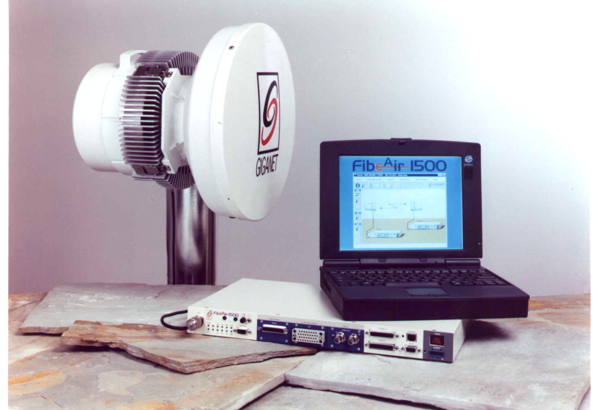
1.1. The FibeAir 1500™ System The system is composed of an Indoor Unit (IDU), an Outdoor Unit (ODU), a high- performance antenna, and a Management subsystem. • The Indoor Unit is a compact, 17” wide, 1U-high unit, that may be mounted in both standard ETSI and ANSI racks. The IDU includes the physical line interfaces, a full-function SDH / SONET regenerator, an advanced modem and a central processing unit (CPU). • The Outdoor Unit (ODU) consists of the RF circuitry, enclosed in a compact weather-proof enclosure, adjacent to the antenna. The ODU connects to the IDU via a single coaxial cable of up to 300m (1000 ft). • The antenna is a 1’ (30cm) or 2’ (60cm) high-performance antenna. • The system is managed either locally or remotely by Giganet’s SNMP-based software, running on either Windows™ or UNIX™ platforms. 1.2. Applications Applications include: • SDH / SONET. • ATM. • Cellular networks. • Corporate / campus networks. • LMDS backhaul. 1.2.1. SDH / SONET Applications SDH access network (STM-1) SDH backbone network (STM-4/16) ADM ADMADM ADM ADM ADMADM ADM Fiber optic STM-1 R T corporate user remote distribution node A: Microwave in the trunk A1- Inter-ring connectivity A2- Wireless segment of SDH ring B: Microwave in the local loop B1- Feeder link to remote distribution node B2- "Last mile" solution for large corporate users RT RT A1 STM-1 R T A2 RT RT B2 STM1 ATM RT RT SDH B1 The FibeAir 1500™ is a natural choice for metropolitan SDH / SONET networks. The system may be used for ring closures, ring interconnects and access to remote distribution nodes, and may be used either as a transparent alternative to fibers, or as a redundant link providing media diversity protection. 1.2.2. ATM Applications The FibeAir 1500™ system is optimized by design for ATM transmission. ATM physical transport: The FibeAir 1500™ provides a direct interface for 155 Mb/s ATM physical transport, with support for UTP, STP, CMI (electrical) and various optical interfaces. Combined with an ARC (ATM Rate Converter), the system provides a simple solution for physical transport of T3 and E3 ATM payloads. Customer Premises Private ATM FibeAir 1500 TM NTU ATM NTU Private ATM Customer Premises Segment OAM “Network end-to-end” ATM control Customer Premises ATM Access Concentrator FibeAir 1500 TM ATM Customer Premises Services ATM PHY PHY ATM PHY Integrated with an ATM NTU (Network Termination Unit) and ATM Access Concentrators, the system provides a combined wireless ATM solution: for interconnecting private ATM networks, or for supporting various services (CBR, VBR and ATM UNI) in the customer’s premises. Building / Campus A On-Fiber STM-1 Terminal Mux Building / Campus B ATM Switch E3 Mux E3 Ethernet 1 Ethernet 2 STM-1 Terminal Mux E3 E3 ATM Switch Mux PBX n x E1 PBX Ethernet 1 Ethernet 2 Fiber Drop 155 Mb/s Off-Fiber FibeAir 1500 TM E3 E3 The FibeAir 1500™ system provides a flexible, cost-effective, transport solution for integrated ATM with non-ATM services.
Schematics
ANTENNA POWER SUPPLY CONTROLLER In-Door Unit MODEM T/R MODULE CABLE COMBINER POWER SUPPLY CONTROLLER Out-Door Unit User Channel FibeAir 1500 - Block Diagram E1 Wayside 155 Mb/s Line - 48 V NMS Station CABLE COMBINER MUX CABLE Outdoor/Indoor Units Block Diagrams MUX Wayside Line User ADC DAC Σ ΣΣ Σ Power Supply Unit Central Processing Unit FEC + ATM MODEM 16 QAM ODU -48VDC / -60VDC 155Mb/s 2Mb/s 64kb/s SLIP / Ethernet Terminal IF module Power Supply Unit Central Processing Unit MMW Converter IDU Synthesizer Σ ΣΣ Σ
Contact Information
Applicant
Sergey Shkolnik(Regulation Engineer)
Technical Specifications
| # | Rule Parts | Frequency Range | Power Output | Emission | Tolerance |
|---|---|---|---|---|---|
| 2 | 101 | 37.00 GHz - 38.40 GHz | 30.00 mW | 50M07DW | 10 ppm |
Other Applications from Ceragon Networks Ltd.

NZ4CRN-FA1500-24
May 10, 2004Point to Point Radio
Equipment Class
DXX - Part 15 Low Power Communication Device Transmitter
NZ4GNT-FA1500-28
Jul 02, 2000Point-to-Point digital radio
Equipment Class
TNB - Licensed Non-Broadcast Station Transmitter