O2700000-30-30
HXI, LLC
Click to zoom
Application Details
- Equipment Class
- DXX - Part 15 Low Power Communication Device Transmitter
- Date of Grant
- Oct 17, 2000
- Application Purpose
- Original Equipment
- Date of Application
- Jun 06, 2000
- Frequency Range
- 59681.20000000 - 63009.00000000
- Company
- HXI, LLC
- Country
- United States
Documents & Files
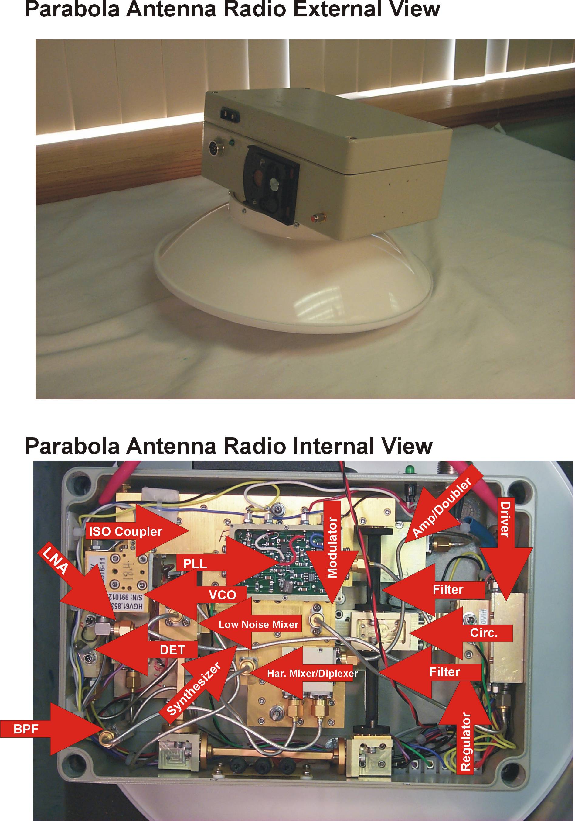
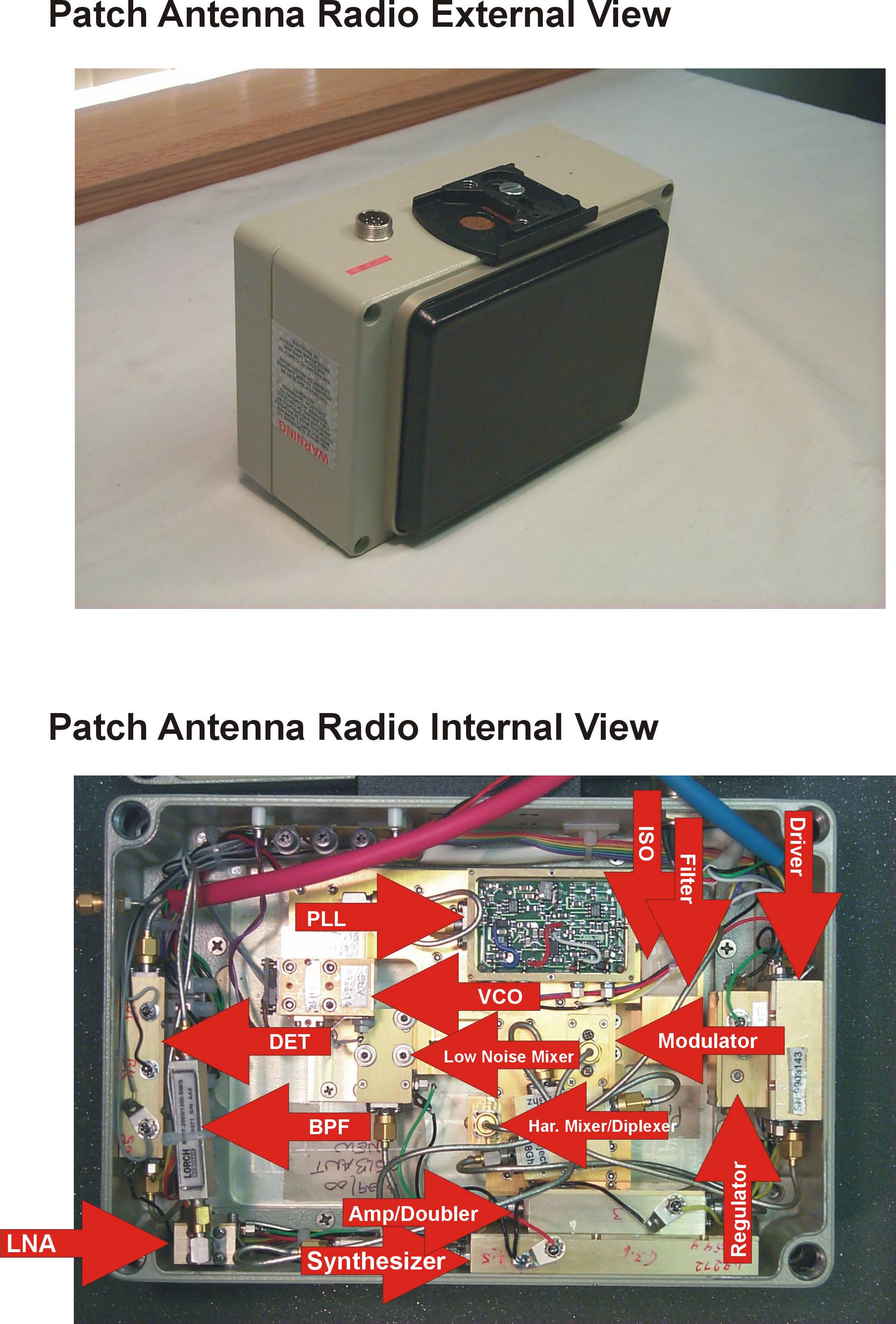
Document Text
Text extracted from the exhibit documents filed with the FCC. Open a document above to read the original.
Users Manual
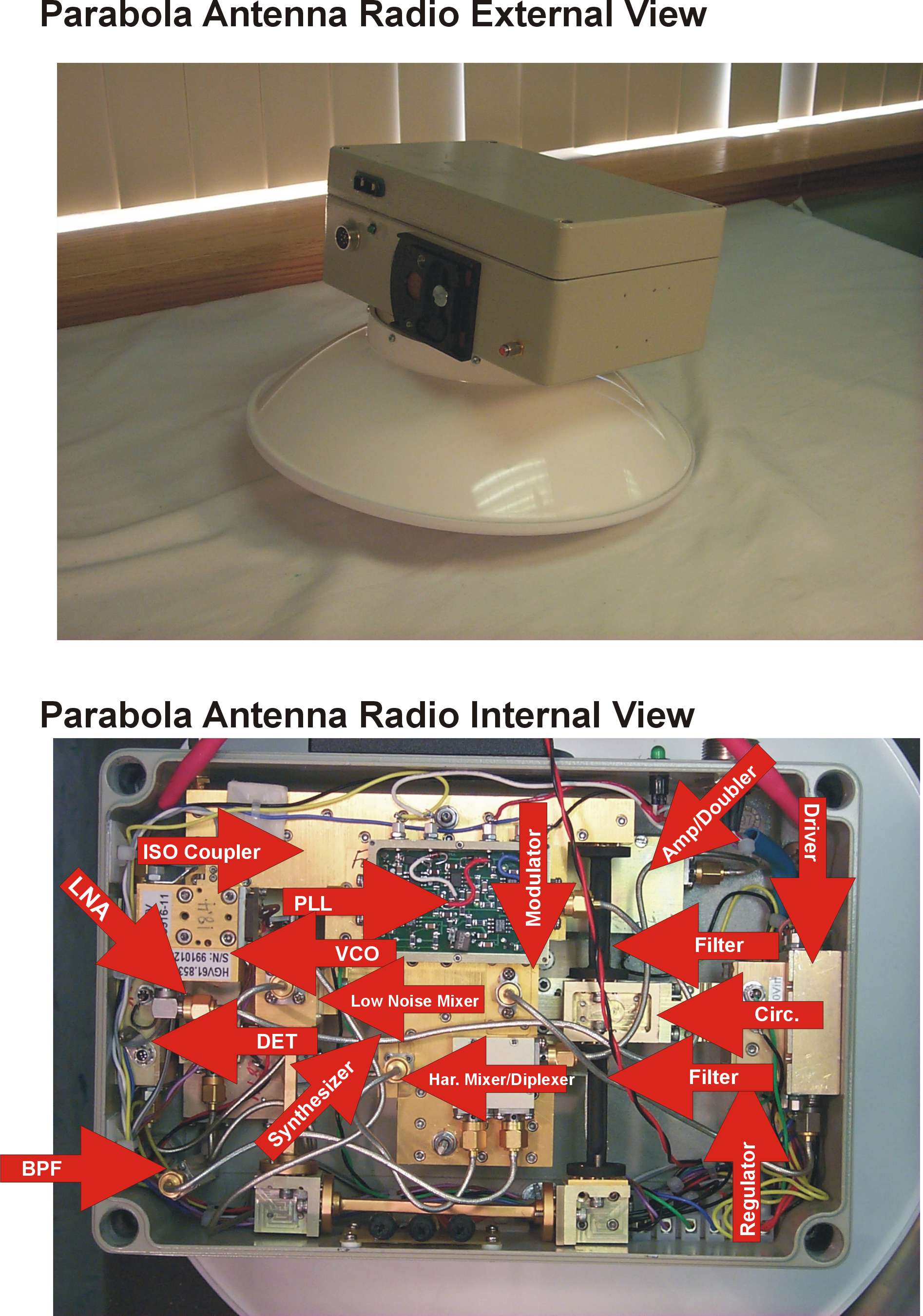
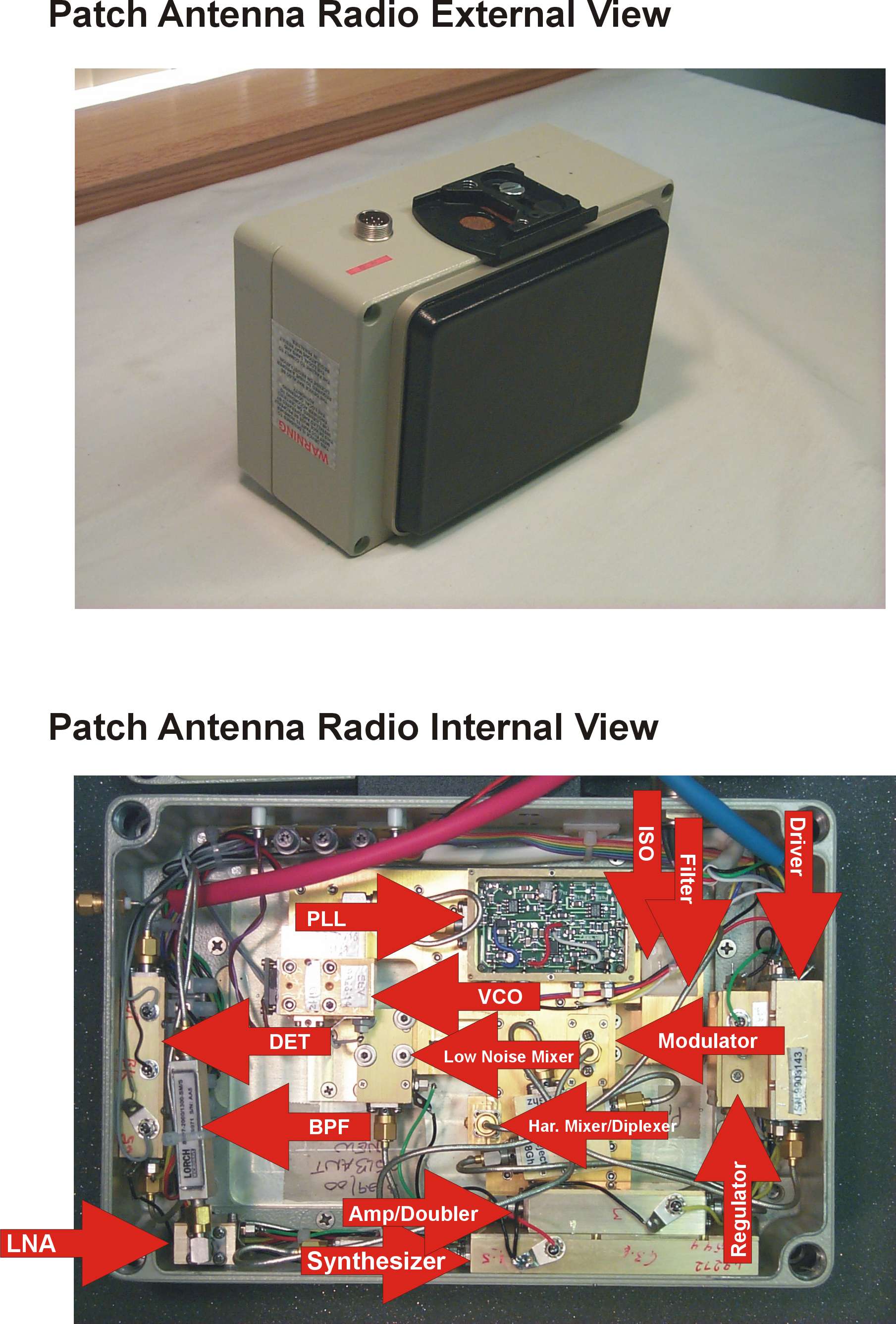
Installation and Operation Manual; Version 1.1 May 22, 2000 Harmonix Corp. 1755 Osgood St. N. Andover, MA 01845 (978) 974 0931, (978) 974 0969 fax www.hxi.com Harmonix GigaLINK Installation and Operating Manual Version 1.1; May 22, 2000 THIS DEVICE COMPLIES WITH PART 15 O F THE FCC RULES. OPERATION IS SUBJECT TO THE FOLLOWING TWO CONDITIONS. (1) THIS DEVICE MAY NOT CAUSE HARMFUL INTERFERENCE, AND (2) THIS DEVICE MUST ACCEPT ANY INTERFERENCE RECEIVED, INCLUDING INTERFERENCE THAT MAY CAUSE UNDESIRED OPERATION. FCCID # XXXXXXXXXXXXX Through the expenditure of substantial time, effort and money, Harmonix Corp. has developed and owns confidential and proprietary information relating to design and development of millimeter wave radio frequency products and signal processing techniques. This manual contains proprietary information granted to our customer only for the specific purposes of installing and operating our millimeter wave radio products. Any use or disclosure of the contained proprietary information for purposes other than that granted is strictly forbidden. All information contained within this document should be considered proprietary and confidential. Installation and Operation Manual; Version 1.1 May 22, 2000 Harmonix Corp. 1755 Osgood St. N. Andover, MA 01845 (978) 974 0931, (978) 974 0969 fax www.hxi.com GigaLINK Introduction and Overview: Thank you for choosing the Harmonix GigaLINK radio system. You have selected the world’s fastest commercially available radio system, thereby demonstrating a discerning grasp of the unique utility of our product. The Harmonix GigaLINK millimeter wave radio system represents an entirely new approach to broadband communications. Based on our extensive experience with millimeter wave systems for military and research applications, we now apply these techniques to a commercially priced version with our ultra-broadband family of GigaLink radio products. The Harmonix GigaLINK broadband radio systems operate in the newly allocated ISM band covering the frequency range of 59.05 – 64.0 GHz. Due to the unlicensed status of this band, no FCC license or special authorization is required to operate our GigaLINK systems. In addition, the high atmospheric absorption of RF energy at this frequency virtually eliminates any chance of interference from competing systems or unauthorized interception of the broadcast signal. The installation procedures detailed within this guide are similar to those used to install any wireless system. In fact, certain attributes of the 59.05 – 64.0 GHz band actually simplify deployment. The key to any successful installation project is proper planning and design. The Harmonix GigaLINK radio product has been designed for ease of installation and trouble-free operation. We recommend that you read and fully understand this guide prior to initiating the actual installation work. As stated above, the key to successful installation is proper system planning and execution. As with most wireless systems, the GigaLINK radio system requires un- obstructed Line of Sight (LOS) to operate reliably. Because of the extremely high data bandwidth provided by the GigaLINK system (100Mbps, OC3 or OC12) it is likely that our radio systems will be utilized as a critical or primary network connection. This absolute reliance on our systems for connectivity demands a focused attention to detail in order to assure un-interrupted operation. Each GigaLINK Radio system configuration is designed to provide a statistical availability of 99.99% for a specific path length. Failure to adhere to the recommend path limits will result in greatly reduced reliability and quality of service. Please follow the installation guidelines contained within and contact Harmonix directly with any questions or problems. The staff at Harmonix Corp. is dedicated to providing our customers the maximum utility in performance, reliability and speed. Installation and Operation Manual; Version 1.1 May 22, 2000 Harmonix Corp. 1755 Osgood St. N. Andover, MA 01845 (978) 974 0931, (978) 974 0969 fax www.hxi.com Table of Contents: SectionPages 1. The Harmonix GigaLINK Product Family a.) Standard Model Description/Specifications b.) Standard Model Range Performance Envelope c.) Available Data protocols/Fiber Types/Termination Styles d.) FCC Part 15, unlicensed operation compliance Statement 2. 60 GHz Millimeter Wave Signal Propagation Basics a.) Oxygen Absorption Spectrum b.) Standard Antenna Beamwidths 3. GigaLINK System Basics 4. GigaLINK Installation Procedure a.) Confirming un-obstructed Line of Sight b.) Path Engineering/Fade Margin Budgeting c.) Selecting proper terminal locations d.) Selecting terminal mounting technique e.) Mechanical installation f.) Electrical and Network Services 5.) RF Terminal Alignment 6.) Network Connection 7.) Troubleshooting and Terminal Maintenance 8.) Harmonix Standard Warranty / Replacement Policy Installation and Operation Manual; Version 1.1 May 22, 2000 Harmonix Corp. 1755 Osgood St. N. Andover, MA 01845 (978) 974 0931, (978) 974 0969 fax www.hxi.com Section 1: The Harmonix GigaLINK Product family The Harmonix GigaLINK product is offered in various configurations for optimum performance for each specific application. Models are offered for 3 different data protocols (100Mbps FX, OC3 and OC12) and with different antenna configuration for reliable performance on varying range RF paths. Standard GigaLINK Product Summary Data Rate (XXX) –Range Meters (XXXX) – Fiber Type (XX) Model No. ProtocolRa nge (M)A nte nnaFi be rTe rmi nat io n* 100-0400-MM100Mbps FX400PatchMultimodeSC 100-0800-MM100Mbps FX80013" ParabolaMultimodeSC 100-1200-MM100Mbps FX1,20013" ParabolaMultimodeSC 155-0400-MMOC3 (155Mbps)400PatchMultimodeSC 155-0800-MMOC3 (155Mbps)80013" ParabolaMultimodeSC 155-1200-MMOC3 (155Mbps)1,20013" ParabolaMultimodeSC 155-0400-SMOC3 (155Mbps)400PatchSingle-modeSC 155-0800-SMOC3 (155Mbps)80013" ParabolaSingle-modeSC 155-…
Text truncated - open the document above for the full version.
Users Manual
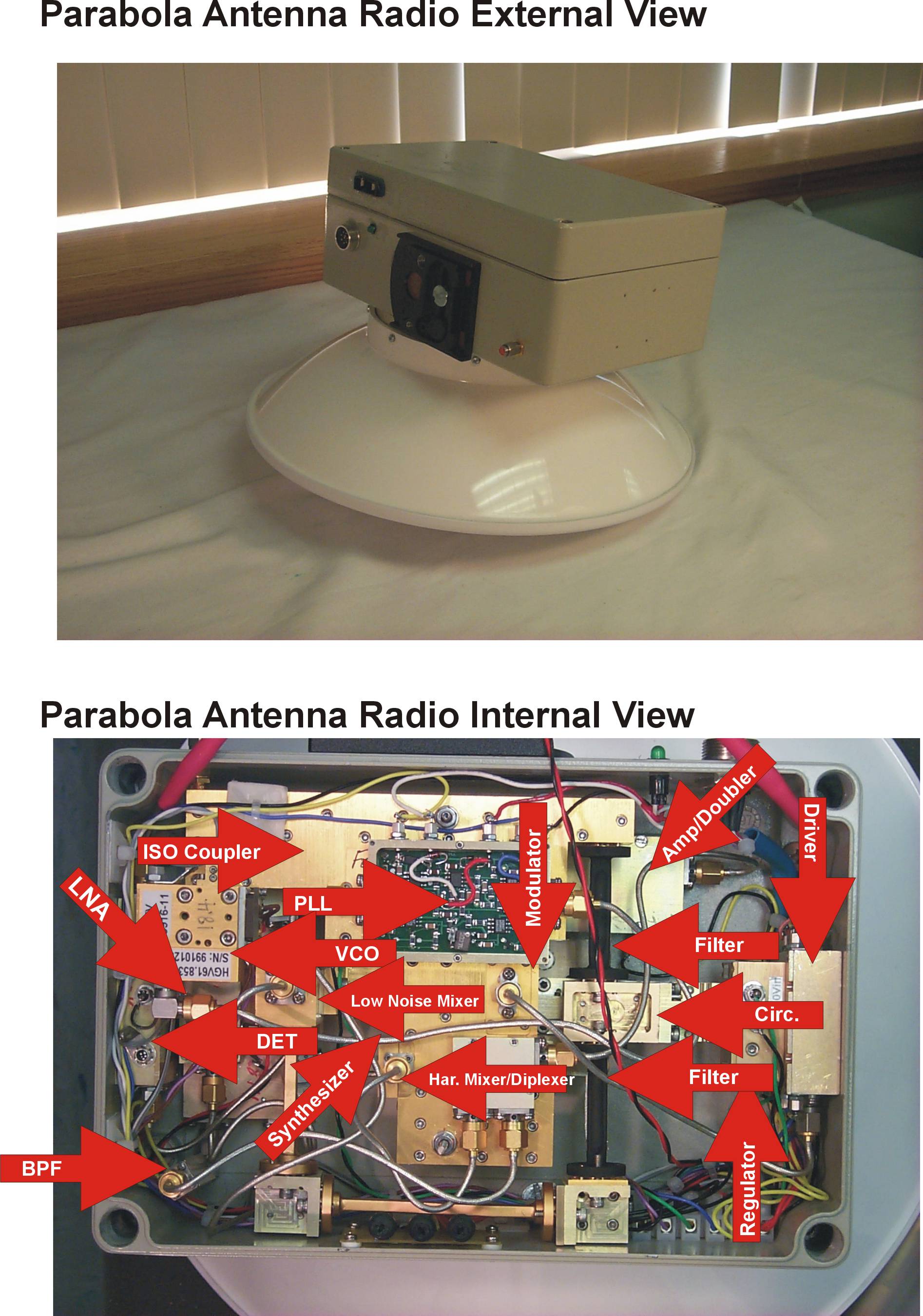
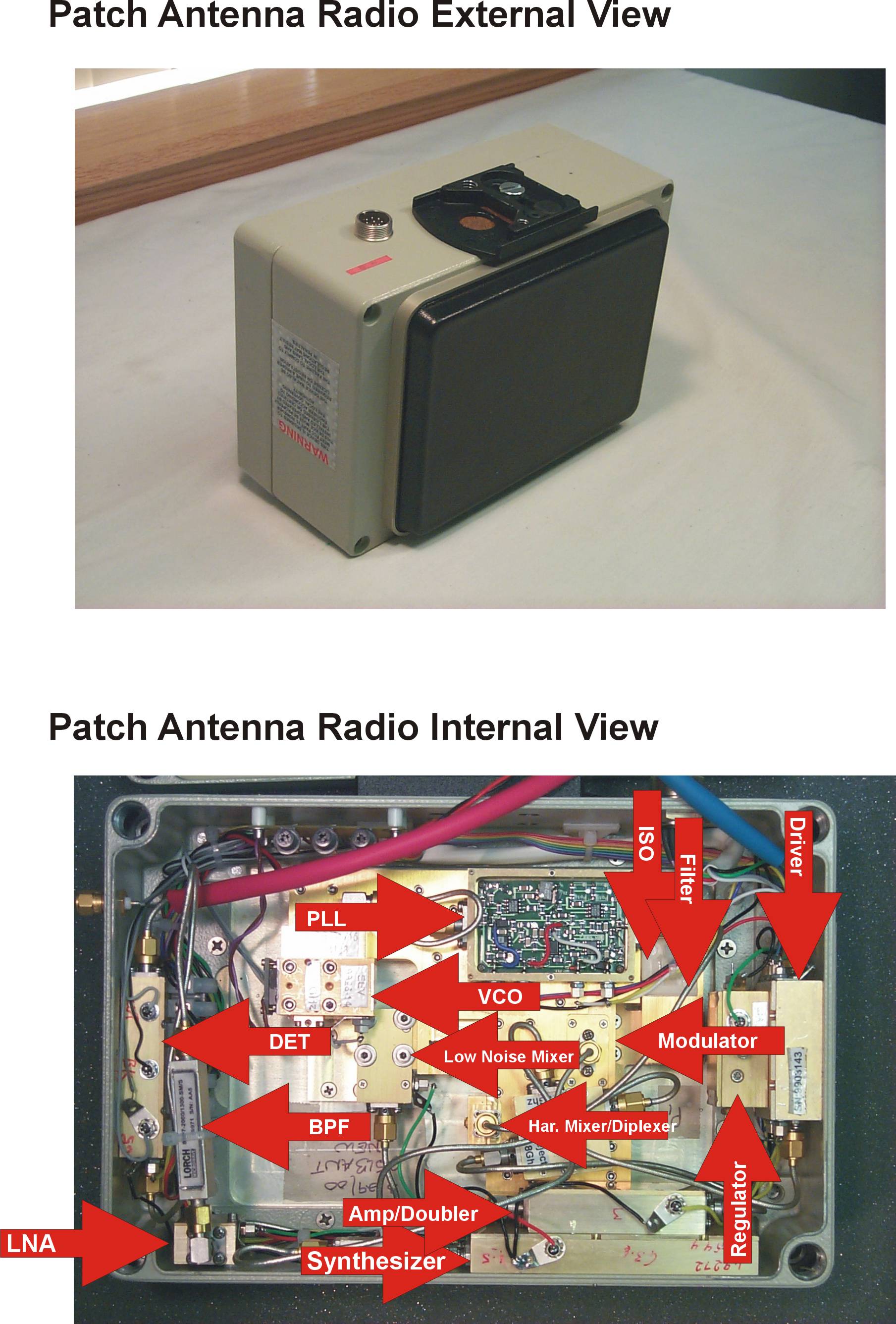
Installation and Operation Manual; Version 1.1 May 22, 2000 Harmonix Corp. 1755 Osgood St. N. Andover, MA 01845 (978) 974 0931, (978) 974 0969 fax www.hxi.com Harmonix GigaLINK Installation and Operating Manual Version 1.1; May 22, 2000 THIS DEVICE COMPLIES WITH PART 15 OF THE FCC RULES. OPERATION IS SUBJECT TO THE FOLLOWING TWO CONDITIONS. (1) THIS DEVICE MAY NOT CAUSE HARMFUL INTERFERENCE, AND (2) THIS DEVICE MUST ACCEPT ANY INTERFERENCE RECEIVED, INCLUDING INTERFERENCE THAT MAY CAUSE UNDESIRED OPERATION. IF THIS PRODUCT IS SUSPECTED OF CAUSING HARMFUL INTERFERENCE WITH OTHER EQUIPMENT, DISCONTINUE OPERATION IMMEDIATELY AND CONTACT HARMONIX CORP. AS SHOWN BELOW. FCCID # O2700000-30-30 Through the expenditure of substantial time, effort and money, Harmonix Corp. has developed and owns confidential and proprietary information relating to design and development of millimeter wave radio frequency products and signal processing techniques. This manual contains proprietary information granted to our customer only for the specific purposes of installing and operating our millimeter wave radio products. Any use or disclosure of the contained proprietary information for purposes other than that granted is strictly forbidden. All information contained within this document should be considered proprietary and confidential. Installation and Operation Manual; Version 1.1 May 22, 2000 Harmonix Corp. 1755 Osgood St. N. Andover, MA 01845 (978) 974 0931, (978) 974 0969 fax www.hxi.com GigaLINK Introduction and Overview: Thank you for choosing the Harmonix GigaLINK radio system. You have selected the world’s fastest commercially available radio system, thereby demonstrating a discerning grasp of the unique utility of our product. The Harmonix GigaLINK millimeter wave radio system represents an entirely new approach to broadband communications. Based on our extensive experience with millimeter wave systems for military and research applications, we now apply these techniques to a commercially priced version with our ultra-broadband family of GigaLink radio products. The Harmonix GigaLINK broadband radio systems operate in the newly allocated ISM band covering the frequency range of 59.05 – 64.0 GHz. Due to the unlicensed status of this band, no FCC license or special authorization is required to operate our GigaLINK systems. In addition, the high atmospheric absorption of RF energy at this frequency virtually eliminates any chance of interference from competing systems or unauthorized interception of the broadcast signal. The installation procedures detailed within this guide are similar to those used to install any wireless system. In fact, certain attributes of the 59.05 – 64.0 GHz band actually simplify deployment. The key to any successful installation project is proper planning and design. The Harmonix GigaLINK radio product has been designed for ease of installation and trouble-free operation. We recommend that you read and fully understand this guide prior to initiating the actual installation work. As stated above, the key to successful installation is proper system planning and execution. As with most wireless systems, the GigaLINK radio system requires un- obstructed Line of Sight (LOS) to operate reliably. Because of the extremely high data bandwidth provided by the GigaLINK system (100Mbps, OC3 or OC12) it is likely that our radio systems will be utilized as a critical or primary network connection. This absolute reliance on our systems for connectivity demands a focused attention to detail in order to assure un-interrupted operation. Each GigaLINK Radio system configuration is designed to provide a statistical availability of 99.99% for a specific path length. Failure to adhere to the recommend path limits will result in greatly reduced reliability and quality of service. Please follow the installation guidelines contained within and contact Harmonix directly with any questions or problems. The staff at Harmonix Corp. is dedicated to providing our customers the maximum utility in performance, reliability and speed. Installation and Operation Manual; Version 1.1 May 22, 2000 Harmonix Corp. 1755 Osgood St. N. Andover, MA 01845 (978) 974 0931, (978) 974 0969 fax www.hxi.com Table of Contents: Section Pages 1. The Harmonix GigaLINK Product Family a.) Standard Model Description/Specifications b.) Standard Model Range Performance Envelope c.) Available Data protocols/Fiber Types/Termination Styles d.) FCC Part 15, unlicensed operation compliance Statement 2. 60 GHz Millimeter Wave Signal Propagation Basics a.) Oxygen Absorption Spectrum b.) Standard Antenna Beamwidths 3. GigaLINK System Basics 4. GigaLINK Installation Procedure a.) Confirming un-obstructed Line of Sight b.) Path Engineering/Fade Margin Budgeting c.) Selecting proper terminal locations d.) Selecting terminal mounting technique e.) Mechanical installation f.) Electrical and Network Services 5.) RF Terminal Alignment 6.) Network Connection 7.) Troubleshooting and Terminal Maintenance 8.) Harmonix Standard Warranty / Replacement Policy Installation and Operation Manual; Version 1.1 May 22, 2000 Harmonix Corp. 1755 Osgood St. N. Andover, MA 01845 (978) 974 0931, (978) 974 0969 fax www.hxi.com Section 1: The Harmonix GigaLINK Product family The Harmonix GigaLINK product is offered in various configurations for optimum performance for each specific application. Models are offered for 3 different data protocols (100Mbps FX, OC3 and OC12) and with different antenna configuration for reliable performance on varying range RF paths. Standard GigaLINK Product Summary Data Rate (XXX) –Range Meters (XXXX) – Fiber Type (XX) Model No. Protocol Range (M) Antenna Fiber Termination* 100-0400-MM 100Mbps FX 400 Patch Multimode SC 100-0800-MM 100Mbps FX 800 13" Parabola Multimode SC 100-1200-MM 100Mbps FX 1,200 13" Parabola Multimode SC 155-0400-MM OC3 (155Mbps) 400 Patch Multimode SC 155-0800-MM OC3 (155Mbps) 800 13" Parabola Multimode SC 155-…
Text truncated - open the document above for the full version.
Users Manual
Installation and Operation Manual; Version 1.1 May 22, 2000 Harmonix Corp. 1755 Osgood St. N. Andover, MA 01845 (978) 974-0931, (978) 974-0969 fax www.hxi.com Harmonix GigaLINK Installation and Operating Manual Version 1.1 May 22, 2000 THIS DEVICE COMPLIES WITH PART 15 O F THE FCC RULES. OPERATION IS SUBJECT TO THE FOLLOWING TWO CONDITIONS. (1) THIS DEVICE MAY NOT CAUSE HARMFUL INTERFERENCE, AND (2) THIS DEVICE MUST ACCEPT ANY INTERFERENCE RECEIVED, INCLUDING INTERFERENCE THAT MAY CAUSE UNDESIRED OPERATION. IF THIS PRODUCT IS SUSPECTED O F CAUSING HARMFUL INTERFERENCE WITH OTHER EQUIPMENT, DISCONTINUE OPERATION IMMEDIATELY AND CONTACT HARMONIX CORP. AS SHO WN BELO W. FCCID # O2700000-30-30 Through the expenditure of substantial time, effort and money, Harmonix Corp. has developed and owns confidential and proprietary information relating to design and development of millimeter wave radio frequency products and signal processing techniques. This manual contains proprietary information granted to our customer only for the specific purposes of installing and operating our millimeter wave radio products. Any use or disclosure of the contained proprietary information for purposes other than that granted is strictly forbidden. All information contained within this document should be considered proprietary and confidential. Installation and Operation Manual; Version 1.1 May 22, 2000 Harmonix Corp. 1755 Osgood St. N. Andover, MA 01845 (978) 974-0931, (978) 974-0969 fax www.hxi.com GigaLINK™ Introduction and Overview Thank you for choosing the Harmonix GigaLINK™ radio system. You have selected the world’s fastest commercially available radio system, thereby demonstrating a discerning grasp of the unique utility of our product. The Harmonix GigaLINK millimeter wave radio system represents an entirely new approach to broadband communications. Based on our extensive experience with millimeter wave systems for military and research applications, we now apply these techniques to a commercially priced version with our ultra-broadband family of GigaLink radio products. The Harmonix GigaLINK broadband radio systems operate in the newly allocated ISM band covering the frequency range of 59.05 – 64.0 GHz. Due to the unlicensed status of this band, FCC license or special authorization is not required to operate our GigaLINK systems. In addition, the high atmospheric absorption of RF energy at this frequency virtually eliminates any chance of interference from competing systems or unauthorized interception of the broadcast signal. The installation procedures detailed within this guide are similar to those used to install any wireless system. In fact, certain attributes of the 59.05 – 64.0 GHz band actually simplify deployment. The key to any successful installation project is proper planning and design. The Harmonix GigaLINK™ radio product has been designed for ease of installation and trouble-free operation. We recommend that you read and fully understand this guide prior to initiating the actual installation work. As stated above, the key to successful installation is proper system planning and execution. As with most wireless systems, the GigaLINK™ radio system requires un- obstructed Line of Sight (LOS) to operate reliably. Because of the extremely high data bandwidth provided by the GigaLINK™ system (100Mbps, OC3 or OC12) it is likely that our radio systems will be utilized as a critical or primary network connection. This absolute reliance on our systems for connectivity demands a focused attention to detail in order to assure un-interrupted operation. Each GigaLINK™ Radio system configuration is designed to provide a statistical availability of 99.99% for a specific path length. Failure to adhere to the recommended path limits will result in greatly reduced reliability and quality of service. Please follow the installation guidelines contained within and contact Harmonix directly with any questions or problems. The staff at Harmonix is dedicated to providing our customers the maximum utility in performance, reliability and speed. Installation and Operation Manual; Version 1.1 May 22, 2000 Harmonix Corp. 1755 Osgood St. N. Andover, MA 01845 (978) 974-0931, (978) 974-0969 fax www.hxi.com Table of Contents SectionPages 1. The Harmonix GigaLINK Product Family a.) Standard Model Description/Specifications b.) Standard Model Range Performance Envelope c.) Available Data protocols/Fiber Types/Termination Styles d.) FCC Part 15, unlicensed operation compliance Statement 2. 60 GHz Millimeter Wave Signal Propagation Basics a.) Oxygen Absorption Spectrum b.) Standard Antenna Beamwidths 3. GigaLINK System Basics 4. GigaLINK™ Installation Procedure a.) Confirming unobstructed Line of Sight b.) Path Engineering/Fade Margin Budgeting c.) Selecting proper terminal locations d.) Selecting terminal mounting technique e.) Mechanical installation f.) Electrical and Network Services 5.) RF Terminal Alignment 6.) Network Connection 7.) Troubleshooting and Terminal Maintenance 8.) Harmonix Standard Warranty/Replacement Policy Installation and Operation Manual; Version 1.1 May 22, 2000 Harmonix Corp. 1755 Osgood St. N. Andover, MA 01845 (978) 974-0931, (978) 974-0969 fax www.hxi.com Section 1: The Harmonix GigaLINK Product Family The Harmonix GigaLINK™ product is offered in various configurations for optimum performance for each specific application. Models are offered for (3) different data protocols (100Mbps FX, OC3 and OC12) and with different antenna configurations for reliable performance on varying range RF paths. Standard GigaLINK Product Summary Data Rate (XXX) –Range Meters (XXXX) – Fiber Type (XX) Model No. ProtocolRa nge (M)A nte nnaFi be rTe rmi nat io n* 100-0400-MM100Mbps FX400PatchMultimodeSC 100-0800-MM100Mbps FX80013" ParabolaMultimodeSC 155-0400-MMOC3 (155Mbps)400PatchMultimodeSC 155-0800-MMOC3 (155Mbps)80013" ParabolaMultimodeSC 155-0400-SMOC3 (155Mbps)400PatchSingle-m…
Text truncated - open the document above for the full version.
Attestation Statements
FCC Ide ntifier The FCC identifier is embedded as a part of maintenance packets/cell in GigaLink Systems. This way, the transmission of FCC identifier becomes transparent to the data communication over the radio systems and allows the user to monitor the health of radio devices that make up the network from a central location. Specifically, the FCC Identifier is embedded in SNMP packets. Thus, the FCC identifier along with device serial number and the status of each radio on the network are received and retransmitted by all the radios within the network. The same serial number is transmitted by each radio on the same network. The attached letter from Karen Rackley of the FCC states that the commission's rules do not require the transmission of a unique manufacture's serial number for each unlicensed device that operates in the 59-64GHz band, so that one serial number can identify all transmitters operation as part of a single communications system, see attached paper. FCC ID in SNMP Packet format Local Network Header Msg Ver si on Local Network Tr ai ler IP Header Header Data Context Engine ID 3 Bytes FCC Grantee ID UDP Header Msg Security Parameters Context Name 11 di gits FCC ID "00-00-30-30" 4 Octets Organizat ion Unique ID Product Unique Seri als Scoped PDU Data Data Data 24 b ytes or more SNMP Message Sample code to view SNMP packet. /* v1.1 WinSNMP.h */ /* v1.0 - Sep 13, 1993 */ /* v1.1 - Jun 10, 1994 */ #ifndef _INC_WINSNMP /* Include WinSNMP declarations */ #define _INC_WINSNMP /* Just once! */ #ifndef _INC_WINDOWS/* Include Windows declarations, if not already done */ #include <windows.h> #define _INC_WINDOWS /* Just once! */ #endif/* _INC_WINDOWS */ #ifdef __cplusplus exter n "C" { #endif /* Wi nSNMP API Type De finitions */ typedef HANDLEHSNMP_SESSION, FAR *LPHSNMP_SESSION; typedef HANDLEHSNMP_ENTITY, FAR *LPHSNMP_ENTITY; typedef HANDLEHSNMP_CONTEXT, FAR *LPHSNMP_CONTEXT; typedef HANDLEHSNMP_PDU,FAR *LPHSNMP_PDU; typedef HANDLEHSNMP_VBL,FAR *LPHSNMP_VBL; typedef unsigned charsmiBYTE,FAR *smiLPBYTE; /* SNMP-related types from RFC1442 (SMI) */ typedef signed longsmiINT,FAR *smiLPINT; typedef smiINTsmiINT32,FAR *smiLPINT32; typedef unsigned longsmiUINT32,FAR *smiLPUINT32; typedef struct { smiUINT32 len; smi LPBYTE ptr;}smiOCTETS,FAR *smi LPOCTETS; typedef const smiOCTETSFAR *smiLPCOCTETS; typedef smiOCTETSsmiBITS,FAR *smi LPBITS; typedef struct { smiUINT32 len; smiLPUINT32 ptr;}smiOID,FAR *smiLPOID; typedef const smiOIDFAR *smiLPCOID; typedef smiOCTETSsmi IPADDR,FAR *smi LPIPADDR; typedef smiUINT32smiCNTR32,FAR *smiLPCNTR32; typedef smiUINT32smiGAUGE32,FAR *smiLPGAUGE32; typedef smiUINT32smiTIMETICKS, FAR *smiLPTIMETICKS; typedef smiOCTETSsmiOPAQUE,FAR *smi LPOPAQUE; typedef smiOCTETSsmiNSAPADDR, FAR *smi LPNSAPADDR; typedef struct { smiUINT32 hipart; smiUINT32 lopart;} smiCNTR64,FAR *smiLPCNTR64; /* ASN/BER Base Types */ /* (used in forming SYNTAXes and certain SNMP types/values) */ #define ASN_UNIVERSAL(0x00) #define ASN_APPLICATION(0x40) #define ASN_CONTEXT(0x80) #define ASN_PRIVATE(0xC0) #define ASN_PRIMITIVE(0x00) #define ASN_CONSTRUCTOR(0x20) /* SNMP ObjectSyntax Values */ #define SNMP_SYNTAX_SEQUENCE(ASN_UNIVERSAL | ASN_CONSTRUCTOR | 0x10) /* These values are used in the "syntax" member of the smiVALUE structure which follows */ #define SNMP_SYNTAX_INT(ASN_UNIVERSAL | ASN_PRIMITIVE | 0x02) #define SNMP_SYNTAX_BITS(ASN_UNIVERSAL | ASN_PRIMITIVE | 0x03) #define SNMP_SYNTAX_OCTETS(ASN_UNIVERSAL | ASN_PRIMITIVE | 0x04) #define SNMP_SYNTAX_NULL(ASN_UNIVERSAL | ASN_PRIMITIVE | 0x05) #define SNMP_SYNTAX_OID(ASN_UNIVERSAL | ASN_PRIMITIVE | 0x06) #define SNMP_SYNTAX_INT32SNMP_SYNTAX_INT #define SNMP_SYNTAX_IPADDR(ASN_APPLICATION | ASN_PRIMITIVE | 0x00) #define SNMP_SYNTAX_CNTR32(ASN_APPLICATION | ASN_PRIMITIVE | 0x01) #define SNMP_SYNTAX_GAUGE32(ASN_APPLICATION | ASN_PRIMITIVE | 0x02) #define SNMP_SYNTAX_TIMETICKS(ASN_APPLICATION | ASN_PRIMITIVE | 0x03) #define SNMP_SYNTAX_OPAQUE(ASN_APPLICATION | ASN_PRIMITIVE | 0x04) #define SNMP_SYNTAX_NSAPADDR(ASN_APPLICATION | ASN_PRIMITIVE | 0x05) #define SNMP_SYNTAX_CNTR64(ASN_APPLICATION | ASN_PRIMITIVE | 0x06) #define SNMP_SYNTAX_UINT32(ASN_APPLICATION | ASN_PRIMITIVE | 0x07) /* Exception conditions in response PDUs for SNMPv2 */ #define SNMP_SYNTAX_NOSUCHOBJECT(ASN_CONTEXT | ASN_PRIMITIVE | 0x00) #define SNMP_SYNTAX_NOSUCHINSTANCE(ASN_CONTEXT | ASN_PRIMITIVE | 0x01) #define SNMP_SYNTAX_ENDOFMIBVIEW(ASN_CONTEXT | ASN_PRIMITIVE | 0x02) typedef struct {/* smiVALUE portion of VarBind */ smiUINT32syntax;/* Insert SNMP_SYNTAX_<type> */ union { smi INTsNumber;/* SNMP_SYNTAX_INT SNMP_SYNTAX_INT32 */ smi UINT32uNumber;/* SNMP_SYNTAX_UINT32 SNMP_SYNTAX_CNTR32 SNMP_SYNTAX_GAUGE32 SNMP_SYNTAX_TIMETICKS */ smiCNTR64hNumber;/* SNMP_SYNTAX_CNTR64 */ smiOCTETSstring;/* SNMP_SYNTAX_OCTETS SNMP_SYNTAX_BITS SNMP_SYNTAX_OPAQUE SNMP_SYNTAX_IPADDR SNMP_SYNTAX_NSAPADDR */ smiOIDoid;/* SNMP_SYNTAX_OID */ smiBYTEempty;/* SNMP_SYNTAX_NULL SNMP_SYNTAX_NOSUCHOBJECT SNMP_SYNTAX_NOSUCHINSTANCE SNMP_SYNTAX_ENDOFMIBVIEW */ }value;/* union */ }smi VALUE,FAR *smi LPVALUE; typedef const smiVALUEFAR *smiLPCVALUE; /* SNMP Limits */ #define MAXOBJIDSIZE 128 /* Max number of components in an OID */ #define MAXOBJIDSTRSIZE1408/* Max len of decoded MAXOBJIDSIZE OID */ /* PDU Type Values */ #define SNMP_PDU_GET(ASN_CONTEXT | ASN_CONSTRUCTOR | 0x0) #define SNMP_PDU_GETNEXT (ASN_CONTEXT | ASN_CONSTRUCTOR | 0x1) #define SNMP_PDU_RESPONSE (ASN_CONTEXT | ASN_CONSTRUCTOR | 0x2) #define SNMP_PDU_SET(ASN_CONTEXT | ASN_CONSTRUCTOR | 0x3) /* SNMP_PDU_V1TRAP is obsolete in SNMPv2 */ #define SNMP_PDU_V1TRAP(ASN_CONTEXT | ASN_CONSTRUCTOR | 0x4) #define SNMP_PDU_GETBULK (ASN_CONTEXT | ASN_CONSTRUCTOR | 0x5) #define SNMP_PDU_INFORM(ASN_CONTEXT | ASN_CONSTRUCTOR | 0x6) #define SNMP_PDU_TRAP(ASN_CONTEXT | ASN_CONSTRUCTOR | 0x7) /* SNMPv1 Trap Values */ /* (These values might be superfluous wrt WinSNMP applications) */ #define SNMP_TRAP_COLDSTART0 #define SNMP_TRAP_WARMSTART1 #define SNMP_TRAP_LIN…
Text truncated - open the document above for the full version.
Attestation Statements
Planned Implementation of FCC Identifier Two levels of FCC identifier embedding are planned The FCC identifier is embedded as part of the maintenance packets/cell in Harmonix's GigaLink system. This allows the transmission of the FCC identifier to become transparent to the data communication over the radio system and allows the user to monitor from a central location the health of radio devices that make up the network. Specifically, the FCC identifier is embedded in SNMP packets/ OAM cells. OAM cell is required to be present every 26 ATM cells. Since ATM Cells are 53 Bytes long, This OAM cells appears every 0.000073 second for OC-3 and every 0.000018 second OC-12. Other ATM spec requires minimum data repetition not to exceed 2 23 -1 bit long. If there is no activities for 2 23 -1 (8,388,607) bits, the switch will inject an OAM cell to maintain DC balance. The drawback of this mechanism is that the FCC identifier, along with device serial number and the status of each radio on the network, is received and retransmitted by all the radios in the network. Every radio in the network transmits the same serial number. The attached letter from Ms. Karen Rackley, Chief of the Technical Rule Branch of the FCC states that the commission's rules do not require the transmission of a unique manufacturer's serial number for each unlicensed device that operates in the 59-64GHz band, therefore one serial number can identify all transmitters operating as part of a single communication system. (See attached paper.) Also, attached is the illustrative sample of OAM (SNMP) structure and decoding software source. The proposed 24-bytes user information is 01234567891011121314151617181920212223 http://www.gigalink.org/ In hex format : 68 74 74 70 3a 2f 2f 77 77 77 2e 67 69 67 61 6c 69 6e 6b 2e 6f 72 67 2f. FCC ID in SNMP Packet format Local Network Header Msg Version Local Network Trailer IP Header Header Data Context Engine ID 3 Bytes FCC Grantee ID UDP Header Msg Security Parameters Context Name 11 digits FCC ID "00-00-30-30" 4 Octets Organization Unique ID Product Unique Serials Scoped PDU Data Data Data 24 bytes or more SNMP Message Sample code to view SNMP packet. /* v1.1 WinSNMP.h */ /* v1.0 - Sep 13, 1993 */ /* v1.1 - Jun 10, 1994 */ #ifndef _INC_WINSNMP /* Include WinSNMP declarations */ #define _INC_WINSNMP /* Just once! */ #ifndef _INC_WINDOWS /* Include Windows declarations, if not already done */ #include <windows.h> #define _INC_WINDOWS /* Just once! */ #endif /* _INC_WINDOWS */ #ifdef __cplusplus extern "C" { #endif /* WinSNMP API Type Definitions */ typedef HANDLE HSNMP_SESSION, FAR *LPHSNMP_SESSION; typedef HANDLE HSNMP_ENTITY, FAR *LPHSNMP_ENTITY; typedef HANDLE HSNMP_CONTEXT, FAR *LPHSNMP_CONTEXT; typedef HANDLE HSNMP_PDU, FAR *LPHSNMP_PDU; typedef HANDLE HSNMP_VBL, FAR *LPHSNMP_VBL; typedef unsigned char smiBYTE, FAR *smiLPBYTE; /* SNMP-related types from RFC1442 (SMI) */ typedef signed long smiINT, FAR *smiLPINT; typedef smiINT smiINT32, FAR *smiLPINT32; typedef unsigned long smiUINT32, FAR *smiLPUINT32; typedef struct { smiUINT32 len; smiLPBYTE ptr;} smiOCTETS, FAR *smiLPOCTETS; typedef const smiOCTETS FAR *smiLPCOCTETS; typedef smiOCTETS smiBITS, FAR *smiLPBITS; typedef struct { smiUINT32 len; smiLPUINT32 ptr;} smiOID, FAR *smiLPOID; typedef const smiOID FAR *smiLPCOID; typedef smiOCTETS smiIPADDR, FAR *smiLPIPADDR; typedef smiUINT32 smiCNTR32, FAR *smiLPCNTR32; typedef smiUINT32 smiGAUGE32, FAR *smiLPGAUGE32; typedef smiUINT32 smiTIMETICKS, FAR *smiLPTIMETICKS; typedef smiOCTETS smiOPAQUE, FAR *smiLPOPAQUE; typedef smiOCTETS smiNSAPADDR, FAR *smiLPNSAPADDR; typedef struct { smiUINT32 hipart; smiUINT32 lopart;} smiCNTR64, FAR *smiLPCNTR64; /* ASN/BER Base Types */ /* (used in forming SYNTAXes and certain SNMP types/values) */ #define ASN_UNIVERSAL (0x00) #defineASN_APPLICATION (0x40) #defineASN_CONTEXT (0x80) #defineASN_PRIVATE (0xC0) #defineASN_PRIMITIVE (0x00) #defineASN_CONSTRUCTOR (0x20) /* SNMP ObjectSyntax Values */ #defineSNMP_SYNTAX_SEQUENCE (ASN_UNIVERSAL | ASN_CONSTRUCTOR | 0x10) /* These values are used in the "syntax" member of the smiVALUE structure which follows */ #define SNMP_SYNTAX_INT (ASN_UNIVERSAL | ASN_PRIMITIVE | 0x02) #define SNMP_SYNTAX_BITS (ASN_UNIVERSAL | ASN_PRIMITIVE | 0x03) #define SNMP_SYNTAX_OCTETS (ASN_UNIVERSAL | ASN_PRIMITIVE | 0x04) #define SNMP_SYNTAX_NULL (ASN_UNIVERSAL | ASN_PRIMITIVE | 0x05) #define SNMP_SYNTAX_OID (ASN_UNIVERSAL | ASN_PRIMITIVE | 0x06) #define SNMP_SYNTAX_INT32 SNMP_SYNTAX_INT #define SNMP_SYNTAX_IPADDR (ASN_APPLICATION | ASN_PRIMITIVE | 0x00) #define SNMP_SYNTAX_CNTR32 (ASN_APPLICATION | ASN_PRIMITIVE | 0x01) #define SNMP_SYNTAX_GAUGE32 (ASN_APPLICATION | ASN_PRIMITIVE | 0x02) #define SNMP_SYNTAX_TIMETICKS(ASN_APPLICATION | ASN_PRIMITIVE | 0x03) #define SNMP_SYNTAX_OPAQUE (ASN_APPLICATION | ASN_PRIMITIVE | 0x04) #define SNMP_SYNTAX_NSAPADDR(ASN_APPLICATION | ASN_PRIMITIVE | 0x05) #define SNMP_SYNTAX_CNTR64 (ASN_APPLICATION | ASN_PRIMITIVE | 0x06) #define SNMP_SYNTAX_UINT32 (ASN_APPLICATION | ASN_PRIMITIVE | 0x07) /* Exception conditions in response PDUs for SNMPv2 */ #define SNMP_SYNTAX_NOSUCHOBJECT (ASN_CONTEXT | ASN_PRIMITIVE | 0x00) #define SNMP_SYNTAX_NOSUCHINSTANCE (ASN_CONTEXT | ASN_PRIMITIVE | 0x01) #define SNMP_SYNTAX_ENDOFMIBVIEW (ASN_CONTEXT | ASN_PRIMITIVE | 0x02) typedef struct { /* smiVALUE portion of VarBind */ smiUINT32 syntax; /* Insert SNMP_SYNTAX_<type> */ union { smiINT sNumber; /* SNMP_SYNTAX_INT SNMP_SYNTAX_INT32 */ smiUINT32 uNumber; /* SNMP_SYNTAX_UINT32 SNMP_SYNTAX_CNTR32 SNMP_SYNTAX_GAUGE32 SNMP_SYNTAX_TIMETICKS */ smiCNTR64 hNumber; /* SNMP_SYNTAX_CNTR64 */ smiOCTETS string; /* SNMP_SYNTAX_OCTETS SNMP_SYNTAX_BITS SNMP_SYNTAX_OPAQUE SNMP_SYNTAX_IPADDR SNMP_SYNTAX_NSAPADDR */ smiOID oid; /* SNMP_SYNTAX_OID */ smiBYTEempty; /* SNMP_SYNTAX_NULL SNMP_SYNTAX_NOSUCHOBJECT SNMP_SYNTAX_NOSUCHINSTANCE SNMP_SYNTAX_ENDOFMIBVIEW */ } value; /* union */ } smiVALUE, FAR *smiLPVALUE; typedef const smiVALUE FAR *smiLPCVALU…
Text truncated - open the document above for the full version.
Contact Information
Applicant
Dave Russell(Product Line Manager, MMW Radios)
Technical Contact
Intertek Testing service, NA Inc.Andrew J Bellezza
[email protected](978) 263-2662
70 Codman Hill Road · Boxborough, Massachusetts · United States
Non-Technical Contact
HarmonixShigeaki(Shey) Hakusui
Technical Specifications
| # | Rule Parts | Frequency Range | Power Output | Tolerance |
|---|---|---|---|---|
| 2 | 15C | 59.68 GHz - 63.01 GHz | - | % |
Other Applications from HXI, LLC

O2700001-30-30
Jan 14, 2003Millimeter wave transmitter
Equipment Class
DXX - Part 15 Low Power Communication Device Transmitter