O2Q-DRTXM3Highway Information System DRTXM3 Transmitter
Highway Information Systems, Inc.
Click to zoom
Application Details
- Equipment Class
- TNB - Licensed Non-Broadcast Station Transmitter
- Date of Grant
- Jan 28, 2003
- Application Purpose
- Original Equipment
- Date of Application
- Jan 28, 2003
- Equipment Note
- Highway Information System DRTXM3 Transmitter
- Frequency Range
- 0.53000000 - 1.70000000
- Country
- United States
Documents & Files
Document Text
Text extracted from the exhibit documents filed with the FCC. Open a document above to read the original.
Users Manual
Model GPS-1 Synchronizer Module Users Manual 4021 Stirrup Creek Dr. Suite 100 Durham, NC 27703 USA December 2002 Tel 800.849.4447 Rev 1.0 Fax 800.849.2947 Copyright 2002 Highway Information Systems, Inc. E:\1 Filings\ARNs FILINGS\USA\Actual Filings\Highway Information\9982 DRTXM3\User's manual\O2Q-DRTXM3 GPS-1 User Manual R03 D04.doc 01/27/03 1 Model GPS-1 Synchronizer Module Users Manual 1. Quick Start Guide......................................................................................................4 1.1. Assemble Components....................................................................................................4 1.2. DC Power Connection....................................................................................................4 1.3. Power Up........................................................................................................................4 1.4. GPS Monitor Program....................................................................................................5 2. GPS-1 Synchronizer Module Overview...................................................................6 2.1. Description......................................................................................................................6 2.2. Features...........................................................................................................................6 3. GPS Transmitter System Functional Description...................................................8 3.1. GPS Transmitter System Block Diagram.......................................................................8 3.2. GPS Timing Receiver and Antenna Subsystem..............................................................8 3.3. GPS-1 Local Oscillator and Divider Chain..................................................................10 3.4. GPS to Local Oscillator Synchronization Circuitry......................................................10 3.5. Transmitter GPS Interface............................................................................................11 3.6. Summary of Frequency Control Operating Modes.......................................................11 4. GPS Synchronized HAR System Setup..................................................................13 4.1. Overview.......................................................................................................................13 4.2. DRTXM3 Transmitter Setup and Checkout in Stand-Alone Mode..............................13 4.3. GPS-1 Synchronizer Setup and Checkout in Stand-Alone Mode.................................15 4.4. GPS-1 Synchronizer & Transmitter Setup and Checkout.............................................16 4.5. GPS Timing Receiver Setup and Checkout..................................................................16 4.6. GPS ThunderBolt Monitor Program Setup and Operation...........................................17 4.7. GPS ThunderBolt Monitor Program Typical Conditions.............................................18 5. Appendix I—List of Monitor Software Functions................................................21 5.1. Serial Communications.................................................................................................21 5.2. Time Functions............................................................................................................. 21 5.3. Position Functions......................................................................................................... 22 5.4. Timing Outputs............................................................................................................. 23 5.5. Critical Alarms.............................................................................................................. 23 5.6. Minor Alarms................................................................................................................ 24 5.7. Disciplining Status........................................................................................................ 25 5.8. Signal Levels.................................................................................................................26 E:\1 Filings\ARNs FILINGS\USA\Actual Filings\Highway Information\9982 DRTXM3\User's manual\O2Q-DRTXM3 GPS-1 User Manual R03 D04.doc 01/27/03 2 FCC COMPLIANCE This AM transmitter complies with Part 90 of the FCC rules. FCC ID: O2Q-DRTXM3 Formal Model Number: DRTXM3 Frequency Range: 0.530 – 1.700 MHz Emission Designator: A3E (6K00A3E) Power: 10 Watts Highway Information Systems, Inc. 4021 Stirrup Creek Drive, Suite 100 Durham NC 27703 Tel: 800.849.4447 Fax: 800.849.2947 E:\1 Filings\ARNs FILINGS\USA\Actual Filings\Highway Information\9982 DRTXM3\User's manual\O2Q-DRTXM3 GPS-1 User Manual R03 D04.doc 01/27/03 3 1. Quick Start Guide 1.1. Assemble Components With the power to the BlackMax rack turned off, assemble the components: (1) Install the DRTXM3 Transmitter in the rack (2) Install the GPS-1 Synchronizer in the rack (3) Connect the circular cable from the rear of the DRTXM3 to the “Output to Transmitter” connector on the GPS-1 (4) Place the antenna outdoors with clear access to the sky (5) Connect the antenna cable to the “GPS Antenna” input (6) Connect the computer’s serial COM port to the RS-232C connector on the GPS-1 ALWAYS SWITCH THE POWER TO THE GPS-1 OFF BEFORE CONNECTING OR DISCONNECTING THE ANTENNA. THIS IS NECESSARY BECAUSE THE ANTENNA CONTAINS ACTIVE ELECTRONIC CIRCUITRY POWERED FROM THE GPS TIMING RECEIVER. CONNECTING OR DISCONNECTING THE ANTENNA OR ANTENNA CABLE WHEN THE UNIT IS POWERED CAN RESULT IN FAILURE OF THE ANTENNA MODULE. 1.2. DC Power Connection For some special applications such as testing, DC power can be fed to the back plane of the BlackMax rack through a jumper cable using a RED (+) and BLACK (-) pigtail jumper. Voltages are as follows: • Nominal: 12 Volts DC • Normal Range: 10.4 to 13.6 Volts DC. • Maximum Range: 10 to 14 Volts DC. • Current…
Text truncated - open the document above for the full version.
Attestation Statements
FCC Labeling Requirements and Information Date: January 23, 2003 American Telecommunications Certification Body, Inc. 6731 Whittier Avenue Suite C110 McLean, VA 22101 RE: FCC Labeling Requirements FCC ID: O2Q-DRTXM3 The following label information is required by the FCC Rules and Regulations for certified devices. Also attached, please find marketing information required by the FCC Rules and Regulations. Thank you for your attention to these matters. Sincerely, Arnom C. Rowe EMC ENGINEER EMC-001375-NE D.L.S. Electronic Systems, Inc. Modification Letter Date: January 23, 2003 American Telecommunications Certification Body, Inc. 6731 Whittier Avenue847-537-6488 Suite C110 McLean, VA 22101 RE: Certification Application FCC ID: O2Q-DRTXM3 Please be advised that the following information is a list of modifications that will be included in the production process for the above-referenced equipment. Change 1: There were no modifications made during testing. Change 2: Change 3: Change 4: Change 5: Change 6: Change 7: Change 8: Change 9 Change 10: Thank you for your attention to this matter. Signatory Arnom C. Rowe EMC ENGINEER EMC-001375-NE D.L.S. Electronic Systems, Inc. Manufacturer’s Letter Date: January 23, 2003 American Telecommunications Certification Body, Inc. 6731 Whittier Avenue Suite C110 McLean, VA 22101 RE: Certification Application FCC ID: O2Q-DRTXM3 To Whom It May Concern: Please be advised that the manufacturer will ensure that the above-referenced model will be manufactured in accordance with the FCC Rules and Regulations. Thank you for your attention to this matter. Signatory Arnom C. Rowe EMC ENGINEER EMC-001375-NE D.L.S. Electronic Systems, Inc.
Cover Letter(s)
Request for Confidentiality Date: January 23, 2003 American Telecommunications Certification Body, Inc. 6731 Whittier Avenue Suite C110 McLean, VA 22101 RE: Certification Application FCC ID: O2Q-DRTXM3 Please be advised that the following information is to be held confidential and behalf of APPLICANT NAME: • Block Diagram • Schematics • Parts Lists The application contains technical information which Highway Information System, Inc. deems to be trade secrets and proprietary. If made public, the information might be used to the disadvantage of the applicant in the market place. Thank you for your attention to this matter. Signatory Arnom C. Rowe EMC ENGINEER EMC-001375-NE D.L.S. Electronic Systems, Inc.
Cover Letter(s)
Letter of Agency Date: January 23, 2003 American Telecommunications Certification Body, Inc. 6731 Whittier Avenue Suite C110 McLean, VA 22101 To Whom It May Concern: Please be advised that Highway Information System, Inc. authorizes D.L.S. Electronic Systems, Inc. to act on our behalf, until otherwise notified, for applications submitted to American Telecommunications Certification Body, Inc. (ATCB). We certify that we are not subject to denial of federal benefits, that includes FCC benefits, pursuant to Section 5301 of the Anti-Drug Abuse ACT of 1988, U.S.C. 862. Further, no party, as defined in 47 CFR 1.2002(b), to the application is subject to denial of federal benefits, that includes FCC benefits. Thank you for your attention to this matter. Signatory, Arnom C. Rowe EMC ENGINEER EMC-001375-NE D.L.S. Electronic Systems, Inc.
Cover Letter(s)
FCC ID: O2Q-DRTXM3 D.L.S. ELECTRONIC SYSTEMS, INC. 1250 Peterson Drive Wheeling, Illinois 60090 FCC Authorization & Evaluation Division 7435 Oakland Mills Road Columbia, Maryland 21045-0429 Gentlemen: We are submitting for Highway Information Systems, Inc., an TIS Low Power AM Transmitter, Model Number DRTXM3, with a FCC ID: O2Q-DRTXM3 for certification. This unit has been tested and complies to Part 90, Subpart J. If there are any questions in regards to this application, please call D.L.S. Electronic Systems, Inc. at (847) 537 6400. Enclosed you will find a copy of our test report with the information and results of tests that is required under Part 90, Section 90.242. Thank you for your assistance in this matter. Sincerely, Arnom C. Rowe EMC-001375-NE DLS/mm
External Photos
Front of Chassis containing the DRTXM3 and the GPS-1 Top of Chassis containing the DRTXM3 and the GPS-1 Bottom of Chassis containing the DRTXM3 and the GPS-1 Back of Chassis containing the DRTXM3 and the GPS-1 DRTXM3 and GPS-1 are removed from Chassis DRTXM3 is connected to the GPS-1 Circular Cable removed from the GPS-1 Left Side of the DRTXM3 Front Side of the DRTXM3 Back Side of the DRTXM3
ID Label/Location Info
Model: DRTXM3 S/N: FCC ID: O2Q-DRTXM3 4021 Stirrup Creek Drive, Suite 100 Durham, NC 27703 USA Tel: 800.849.4447 Fax: 800.849.2947 Highway Information Systems, Inc. A Quixote Company Artwork original as shown is 200% Finished size is 1.6” high x 3“ wide Finished font is 8 pt Arial Label is located on rear of module Label is visible through openings in rack when installed FCC LABEL Location on the DRTXM3
Internal Photos
Right Side Cover of the DRTXM3 removed Component/LED side of the DRTXM3 circuit board “DRTXM2DTR PCB” Solder/LED side of the DRTXM3 circuit board “DRTXM2DTR PCB” Component side of the DRTXM3 Circuit Board “GPS TRANSMITTER INTERFACE Board Rev A” Solder side of the DRTXM3 Circuit Board “GPS TRANSMITTER INTERFACE Board Rev A” Front Half (component side) of the DRTXM3 Circuit Board “DRTXM2MAIN Print Circuit Board Rev A” Back Half (component side) of the DRTXM3 Circuit Board “DRTXM2MAIN Print Circuit Board Rev A” Front Half (solder side) of the DRTXM3 Circuit Board “DRTXM2MAIN Print Circuit Board Rev A” Back Half (solder side) of the DRTXM3 Circuit Board “DRTXM2MAIN Print Circuit Board Rev A” Inside Covers of the DRTXM3 Left Side of the GPS-1 Front Side of the GPS-1 Back Side of the GPS-1 Right Side Cover of the GPS-1 removed Front Half (component side) of the GPS-1 Circuit Board “GPS SYNCHRONIZER Board Rev A” Back Half (component side) of the GPS-1 Circuit Board “GPS SYNCHRONIZER Board Rev A” Front Half (solder side) of the GPS-1 Circuit Board “GPS SYNCHRONIZER Board Rev A” Back Half (solder side) of the GPS-1 Circuit Board “GPS SYNCHRONIZER Board Rev A” Inside Covers of the GPS-1
Operational Description
1. GPS Transmitter System Functional Description 1.1. GPS Transmitter System Block Diagram A block diagram of the GPS synchronized transmitter system is provided as a separate document and is referred to below. 1.2. GPS Timing Receiver and Antenna Subsystem At the upper left of the block diagram is the GPS timing receiver and antenna subsystem. These units differ from the usual hand-held GPS receiver used for position location in that they have a precision ovenized oscillator that is phase locked to GPS standard time. 1.2.1. GPS Antenna The GPS timing receiver picks up the transmissions from the GPS satellites using the GPS antenna connected to the receiver through a 75 Ω coaxial cable. For convenience in connecting the system, a front-panel connector is provided 1.2.2. GPS Timing Receiver The GPS timing receiver is mounted inside the GPS-1 Synchronizer module and it draws its power from the BlackMax Rack. The outputs from the GPS timing receiver are a 10 MHz sine wave and a 1 PPS (pulse per second) digital pulse both locked to GPS standard time within 50 nano seconds (0.000 000 050 seconds) or less. The green front-panel LED indicators for “GPS 10 MHz” and “GPS 1 PPS” indicate the presence of these signals. Note, however, that these signals will be produced whenever the GPS timing receiver is operating, whether or not it is locked to absolute GPS time. Thus, the presence of these signals as indicated by the front-panel LEDs does not assure that the system is locked to GPS time. This can only be determined by monitoring the serial output of the GPS timing receiver, as described below in Section 3.2.3. 1.2.3. GPS Receiver Monitor Program Running on a PC In the upper left of the block diagram is a desktop or laptop personal computer (PC) running a program that monitors and reports the status of the GPS timing receiver inside the GPS-1 Synchronizer module. As shown in the figure, the computer is connected through a standard serial cable to the front panel connector on the GPS-1 labeled “RS-232C.” E:\1 Filings\ARNs FILINGS\USA\Actual Filings\Highway Information\9982 DRTXM3\Operational Description\O2Q-DRTXM3 Principle of Operation.doc 01/27/03 1 1.3. GPS-1 Local Oscillator and Divider Chain 1.3.1. GPS-1 Local Oscillator At the upper right of the block diagram is the GPS-1 local oscillator. This oscillator is a voltage-controlled crystal oscillator (VCXO), whose frequency and phase can be fine tuned by the application of a control voltage. 1.3.2. GPS-1 Local Oscillator Operating Modes In normal operation, the synchronization circuitry (to be described below) keeps the GPS-1 local oscillator precisely phase locked with the 10 MHz and 1 PPS signals from the GPS timing receiver. If the GPS 10 MHz signal is not present, the synchronization circuit automatically switches the GPS-1 oscillator over to GPS-1 manual control mode. In GPS-1 manual control mode the oscillator no longer has the precision of a GPS oscillator, but rather, has the precision typical of a standard HAR transmitter. Note that the various frequency control modes mentioned throughout this chapter are summarized at the end of the chapter. 1.3.3. RF Divider Chain The RF divider chain shown below the GPS-1 local oscillator divides the oscillator frequency down to the RF frequency of the transmitter. This signal is fed to the transmitter via the front-panel circular connector labeled “Output to Transmitter” and then travels through the circular cable through the rear of the transmitter cabinet to the Transmitter GPS interface adapter board inside the transmitter. 1.4. GPS to Local Oscillator Synchronization Circuitry 1.4.1. Synchronization Circuitry The synchronization circuitry block shown near the top center of the diagram synchronizes the GPS-1 local oscillator to the GPS timing signals. This is accomplished by dividing both the 10 MHz GPS timing signal and the GPS-1 local oscillator signal down to the greatest common divisor, namely 10 kHz (10,000 Hz). The synchronization circuitry then uses a phase-locked-loop circuit to precisely control the phase and frequency of the local oscillator so that it is always precisely synchronized with the GPS timing signals. 1.4.2. RF Phase Degrees Control The front-panel “RF Phase Degrees Control” connects to the synchronization circuitry and precisely changes the phase of the local oscillator relative to the GPS timing signals so that the phase of the RF output from the transmitter can be adjusted through the full 360 degrees. In fact, the range of the adjustment is 000 to 999 degrees, but use of values greater than 360 is both unnecessary and not recommended. E:\1 Filings\ARNs FILINGS\USA\Actual Filings\Highway Information\9982 DRTXM3\Operational Description\O2Q-DRTXM3 Principle of Operation.doc 01/27/03 2 1.5. Transmitter GPS Interface 1.5.1. Transmitter GPS Interface Adapter Board Shown in the lower right of the block diagram is a dotted line corresponding to the DRTXM3 Transmitter. Located in the transmitter is the Transmitter GPS Interface Adapter Board which processes the frequency control signals from the GPS-1 Synchronizer module to make them suitable for controlling the transmitter RF. 1.5.2. Transmitter Local Oscillator Switching Function The transmitter GPS interface adapter board incorporates a switching function such that if the frequency control signals from the GPS-1 are present, the transmitter will be under GPS control, but if these signals are not present, the transmitter will automatically switch over to operate from its own local oscillator. 1.5.3. Transmitter Lock LED The transmitter GPS interface adapter board also generates the “Transmitter Lock” signal which is fed to the front panel LED on the GPS-1 Synchronizer. When this LED is lit it indicates that the transmitter is operating properly from the signal being provided from the GPS-1 synchronizer. Note that it does not necessarily indicate that the system is locked to the GPS time signal, which can only be determined usin…
Text truncated - open the document above for the full version.
Test Report
Company: Highway Information Systems, Inc. Model Tested: DRTXM3 Report Number: 9982 1250 Peterson Drive, Wheeling, Illinois 60090 TEST MODE 2 (Without GPS-1 Synchronizer) Page 46 Company: Highway Information Systems, Inc. Model Tested: DRTXM3 Report Number: 9982 1250 Peterson Drive, Wheeling, Illinois 60090 TEST MODE 2 (Without GPS-1 Synchronizer) Page 47 Company: Highway Information Systems, Inc. Model Tested: DRTXM3 Report Number: 9982 1250 Peterson Drive, Wheeling, Illinois 60090 TEST MODE 2 (Without GPS-1 Synchronizer) Page 48 Company: Highway Information Systems, Inc. Model Tested: DRTXM3 Report Number: 9982 1250 Peterson Drive, Wheeling, Illinois 60090 TEST MODE 2 (Without GPS-1 Synchronizer) Page 49 Company: Highway Information Systems, Inc. Model Tested: DRTXM3 Report Number: 9982 1250 Peterson Drive, Wheeling, Illinois 60090 TEST MODE 2 (Without GPS-1 Synchronizer) Page 50 Company: Highway Information Systems, Inc. Model Tested: DRTXM3 Report Number: 9982 1250 Peterson Drive, Wheeling, Illinois 60090 TEST MODE 2 (Without GPS-1 Synchronizer) Page 51 Company: Highway Information Systems, Inc. Model Tested: DRTXM3 Report Number: 9982 1250 Peterson Drive, Wheeling, Illinois 60090 TEST MODE 2 (Without GPS-1 Synchronizer) Page 52 Company: Highway Information Systems, Inc. Model Tested: DRTXM3 Report Number: 9982 1250 Peterson Drive, Wheeling, Illinois 60090 TEST MODE 2 (Without GPS-1 Synchronizer) Page 53 Company: Highway Information Systems, Inc. Model Tested: DRTXM3 Report Number: 9982 1250 Peterson Drive, Wheeling, Illinois 60090 TEST MODE 2 (Without GPS-1 Synchronizer) Page 54 Company: Highway Information Systems, Inc. Model Tested: DRTXM3 Report Number: 9982 1250 Peterson Drive, Wheeling, Illinois 60090 TEST MODE 3 (Without 1 PPS Timing Signal) Page 55 Company: Highway Information Systems, Inc. Model Tested: DRTXM3 Report Number: 9982 1250 Peterson Drive, Wheeling, Illinois 60090 TEST MODE 3 (Without 1 PPS Timing Signal) Page 56 Company: Highway Information Systems, Inc. Model Tested: DRTXM3 Report Number: 9982 1250 Peterson Drive, Wheeling, Illinois 60090 TEST MODE 3 (Without 1 PPS Timing Signal) Page 57 Company: Highway Information Systems, Inc. Model Tested: DRTXM3 Report Number: 9982 1250 Peterson Drive, Wheeling, Illinois 60090 TEST MODE 3 (Without 1 PPS Timing Signal) Page 58 Company: Highway Information Systems, Inc. Model Tested: DRTXM3 Report Number: 9982 1250 Peterson Drive, Wheeling, Illinois 60090 TEST MODE 3 (Without 1 PPS Timing Signal) Page 59 Company: Highway Information Systems, Inc. Model Tested: DRTXM3 Report Number: 9982 1250 Peterson Drive, Wheeling, Illinois 60090 TEST MODE 3 (Without 1 PPS Timing Signal) Page 60 Company: Highway Information Systems, Inc. Model Tested: DRTXM3 Report Number: 9982 1250 Peterson Drive, Wheeling, Illinois 60090 TEST MODE 3 (Without 1 PPS Timing Signal) Page 61 Company: Highway Information Systems, Inc. Model Tested: DRTXM3 Report Number: 9982 1250 Peterson Drive, Wheeling, Illinois 60090 TEST MODE 3 (Without 1 PPS Timing Signal) Page 62 Company: Highway Information Systems, Inc. Model Tested: DRTXM3 Report Number: 9982 1250 Peterson Drive, Wheeling, Illinois 60090 TEST MODE 3 (Without 1 PPS Timing Signal) Page 63
Test Report
Company: Highway Information Systems, Inc. Model Tested: DRTXM3 Report Number: 9982 1250 Peterson Drive, Wheeling, Illinois 60090 TEST MODE 4 (Without 10 MHz Timing Signal) Page 64 Company: Highway Information Systems, Inc. Model Tested: DRTXM3 Report Number: 9982 1250 Peterson Drive, Wheeling, Illinois 60090 TEST MODE 4 (Without 10 MHz Timing Signal) Page 65 Company: Highway Information Systems, Inc. Model Tested: DRTXM3 Report Number: 9982 1250 Peterson Drive, Wheeling, Illinois 60090 TEST MODE 4 (Without 10 MHz Timing Signal) Page 66 Company: Highway Information Systems, Inc. Model Tested: DRTXM3 Report Number: 9982 1250 Peterson Drive, Wheeling, Illinois 60090 TEST MODE 4 (Without 10 MHz Timing Signal) Page 67 Company: Highway Information Systems, Inc. Model Tested: DRTXM3 Report Number: 9982 1250 Peterson Drive, Wheeling, Illinois 60090 TEST MODE 4 (Without 10 MHz Timing Signal) Page 68 Company: Highway Information Systems, Inc. Model Tested: DRTXM3 Report Number: 9982 1250 Peterson Drive, Wheeling, Illinois 60090 TEST MODE 4 (Without 10 MHz Timing Signal) Page 69 Company: Highway Information Systems, Inc. Model Tested: DRTXM3 Report Number: 9982 1250 Peterson Drive, Wheeling, Illinois 60090 TEST MODE 4 (Without 10 MHz Timing Signal) Page 70 Company: Highway Information Systems, Inc. Model Tested: DRTXM3 Report Number: 9982 1250 Peterson Drive, Wheeling, Illinois 60090 TEST MODE 4 (Without 10 MHz Timing Signal) Page 71 Company: Highway Information Systems, Inc. Model Tested: DRTXM3 Report Number: 9982 1250 Peterson Drive, Wheeling, Illinois 60090 TEST MODE 4 (Without 10 MHz Timing Signal) Page 72 Company: Highway Information Systems, Inc. Model Tested: DRTXM3 Report Number: 9982 1250 Peterson Drive, Wheeling, Illinois 60090 TEST MODE 5 (Without Satellite Reception) Page 73 Company: Highway Information Systems, Inc. Model Tested: DRTXM3 Report Number: 9982 1250 Peterson Drive, Wheeling, Illinois 60090 TEST MODE 5 (Without Satellite Reception) Page 74 Company: Highway Information Systems, Inc. Model Tested: DRTXM3 Report Number: 9982 1250 Peterson Drive, Wheeling, Illinois 60090 TEST MODE 5 (Without Satellite Reception) Page 75 Company: Highway Information Systems, Inc. Model Tested: DRTXM3 Report Number: 9982 1250 Peterson Drive, Wheeling, Illinois 60090 TEST MODE 5 (Without Satellite Reception) Page 76 Company: Highway Information Systems, Inc. Model Tested: DRTXM3 Report Number: 9982 1250 Peterson Drive, Wheeling, Illinois 60090 TEST MODE 5 (Without Satellite Reception) Page 77 Company: Highway Information Systems, Inc. Model Tested: DRTXM3 Report Number: 9982 1250 Peterson Drive, Wheeling, Illinois 60090 TEST MODE 5 (Without Satellite Reception) Page 78 Company: Highway Information Systems, Inc. Model Tested: DRTXM3 Report Number: 9982 1250 Peterson Drive, Wheeling, Illinois 60090 TEST MODE 5 (Without Satellite Reception) Page 79 Company: Highway Information Systems, Inc. Model Tested: DRTXM3 Report Number: 9982 1250 Peterson Drive, Wheeling, Illinois 60090 TEST MODE 5 (Without Satellite Reception) Page 80 Company: Highway Information Systems, Inc. Model Tested: DRTXM3 Report Number: 9982 1250 Peterson Drive, Wheeling, Illinois 60090 TEST MODE 5 (Without Satellite Reception) Page 81
Test Report
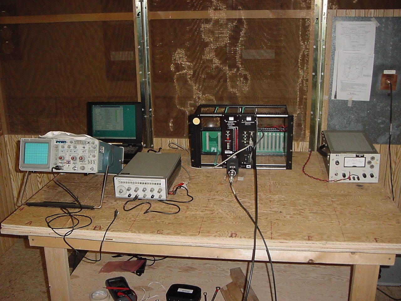
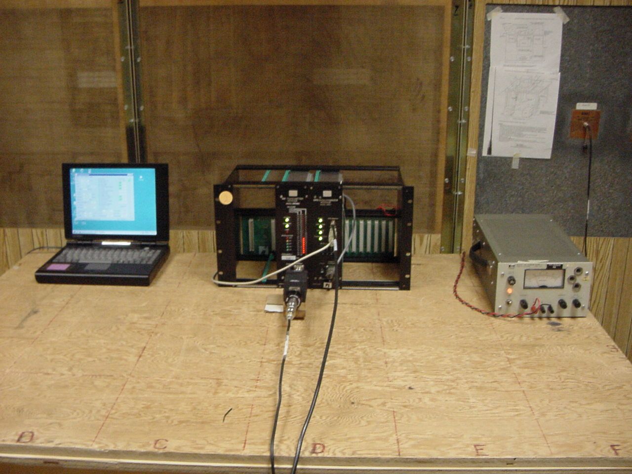
Company: Highway Information Systems, Inc. Model Tested: DRTXM3 Report Number: 9982 1250 Peterson Drive, Wheeling, Illinois 60090 11.0 FREQUENCY STABILITY - PART 2.1055 (d)(1) (Voltage Variation) The frequency stability of Highway Information System DRTXM3 Transmitter was measured by varying the primary supply voltage from 85% to 115% of nominal value. FREQUENCY STABILITY FOR VOLTAGE VARIATION: From 100% to 85% = 2.00400802 Hz (10 volts to 12 volts) From 100% to 115% = 0 Hz (14 volts to 12 volts) Page 82 Company: Highway Information Systems, Inc. Model Tested: DRTXM3 Report Number: 9982 1250 Peterson Drive, Wheeling, Illinois 60090 GRAPH(S) TAKEN FOR FREQUENCY STABILITY WHEN VARYING THE PRIMARY SUPPLY VOLTAGE PART 2.1055d Page 83 Company: Highway Information Systems, Inc. Model Tested: DRTXM3 Report Number: 9982 1250 Peterson Drive, Wheeling, Illinois 60090 10 Volts vs 12 Volts (min) Test Mode 1 (Fully Locked) Page 84 Company: Highway Information Systems, Inc. Model Tested: DRTXM3 Report Number: 9982 1250 Peterson Drive, Wheeling, Illinois 60090 14 Volts vs 12 Volts (max) Test Mode 1 (Fully Locked) Page 85 Company: Highway Information Systems, Inc. Model Tested: DRTXM3 Report Number: 9982 1250 Peterson Drive, Wheeling, Illinois 60090 10 Volts vs 12 Volts (min) Test Mode 2 (Without GPS-1 Synchronizer) Page 86 Company: Highway Information Systems, Inc. Model Tested: DRTXM3 Report Number: 9982 1250 Peterson Drive, Wheeling, Illinois 60090 14 Volts vs 12 Volts (max) Test Mode 2 (Without GPS-1 Synchronizer) Page 87 Company: Highway Information Systems, Inc. Model Tested: DRTXM3 Report Number: 9982 1250 Peterson Drive, Wheeling, Illinois 60090 10 Volts vs 12 Volts (min) Test Mode 3 (Without 1 PPS Timing Signal) Page 88 Company: Highway Information Systems, Inc. Model Tested: DRTXM3 Report Number: 9982 1250 Peterson Drive, Wheeling, Illinois 60090 14 Volts vs 12 Volts (max) Test Mode 3 (Without 1 PPS Timing Signal) Page 89 Company: Highway Information Systems, Inc. Model Tested: DRTXM3 Report Number: 9982 1250 Peterson Drive, Wheeling, Illinois 60090 10 Volts vs 12 Volts (min) Test Mode 4 (Without 10 MHz Timing Signal) Page 90 Company: Highway Information Systems, Inc. Model Tested: DRTXM3 Report Number: 9982 1250 Peterson Drive, Wheeling, Illinois 60090 14 Volts vs 12 Volts (max) Test Mode 4 (Without 10 MHz Timing Signal) Page 91 Company: Highway Information Systems, Inc. Model Tested: DRTXM3 Report Number: 9982 1250 Peterson Drive, Wheeling, Illinois 60090 10 Volts vs 12 Volts (min) Test Mode 5 (Without Satellite Reception) Page 92 Company: Highway Information Systems, Inc. Model Tested: DRTXM3 Report Number: 9982 1250 Peterson Drive, Wheeling, Illinois 60090 14 Volts vs 12 Volts (max) Test Mode 5 (Without Satellite Reception) Page 93 Company: Highway Information Systems, Inc. Model Tested: DRTXM3 Report Number: 9982 1250 Peterson Drive, Wheeling, Illinois 60090 12.0 PHOTO INFORMATION AND TEST SET-UP The test set-up can be seen on the accompanying photo page. Item 0 Highway Information System DRTXM3 Transmitter FCC ID#: O2Q-DRTXM3 SN: DRTXM3-0001 Item 1 Item 2 Item 3 Item 4 Item 5 Item 6 Item 7 Item 8 Item 9 Item 10 Page 94 Company: Highway Information Systems, Inc. Model Tested: DRTXM3 Report Number: 9982 1250 Peterson Drive, Wheeling, Illinois 60090 13.0 PHOTOS TAKEN DURING TESTING. Page 95 Company: Highway Information Systems, Inc. Model Tested: DRTXM3 Report Number: 9982 1250 Peterson Drive, Wheeling, Illinois 60090 13.0 PHOTOS TAKEN DURING TESTING Page 96 Company: Highway Information Systems, Inc. Model Tested: DRTXM3 Report Number: 9982 1250 Peterson Drive, Wheeling, Illinois 60090 14.0 CHANGE INFORMATION The following changes were implemented during the testing and must be incorporated into the production units to ensure compliance. Change 1. Change 2. Change 3. Change 4. Change 5. Page 97 Company: Highway Information Systems, Inc. Model Tested: DRTXM3 Report Number: 9982 1250 Peterson Drive, Wheeling, Illinois 60090 14.0 CHANGE INFORMATION (CON’T) Change 6. Change 7. Change 8. Change 9. Change 10. NOTE: Tested with the rack that it is normally installed in. The responsibility of implementing the changes listed in this report is accepted or I certify that no changes were made. by _____________________________________ ____________________________________ Signature Title for _____________________________________ ____________________________________ Company Name Date Page 98 Company: Highway Information Systems, Inc. Model Tested: DRTXM3 Report Number: 9982 1250 Peterson Drive, Wheeling, Illinois 60090 15.0 RESULTS OF TESTS The emission test results can be seen on pages at the end of this report. Data sheets indicating the emission measurements can also be found with this report. 16.0 CONCLUSION It was found that the Highway Information System DRTXM3 Transmitters, S/N: DRTXM3-0001 meets the requirements for conducted spurious emissions as specified in the FCC "Rules and Regulations", Part 90, Private Land Mobile Services, Subpart J, Sections 90.205 to 90.210 & 90.242 for Travelers’ Information Stations, operating in the 530 kHz to 1700 kHz Frequency Band. This test report relates only to the items tested and contains the following number of pages: Text: 29 pages Charts: 71 pages Total Pages: 100 pages Page 99 Company: Highway Information Systems, Inc. Model Tested: DRTXM3 Report Number: 9982 1250 Peterson Drive, Wheeling, Illinois 60090 TABLE 1 - EQUIPMENT LIST Test Equipment Manufacturer/ Description Model Number Seri…
Text truncated - open the document above for the full version.
Contact Information
Applicant
Tom Hall(General Manager)
Technical Contact
D.L.S. Electronic Systems, IncArnom Rowe
[email protected]847-537-6400
1250 Peterson Drive · Wheeling, Illinois · United States
Test Firm
DLS Electronic Systems, Inc.William Stumpf
Technical Specifications
| # | Rule Parts | Frequency Range | Power Output | Emission | Tolerance |
|---|---|---|---|---|---|
| 1 | 90.210 | 0.53 MHz - 1.7 MHz | 10 W | 6K00A3E | 100.0000000000 Hz |
Other Applications from Highway Information Systems, Inc.

O2Q-DRTXM4
Feb 22, 2006AM Broadcast Transmitter
Equipment Class
TNB - Licensed Non-Broadcast Station Transmitter
O2Q-DRTXM2
Jun 27, 2000TIS Low Power AM Transmitter
Equipment Class
TNB - Licensed Non-Broadcast Station Transmitter