O4D-2012-003-SNBCommunication Module
Fujitsu Limited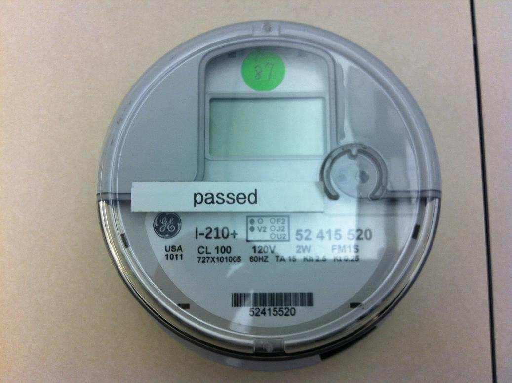
Click to zoom
Application Details
- Equipment Class
- DTS - Digital Transmission System
- Date of Grant
- Mar 14, 2013
- Application Purpose
- Original Equipment
- Date of Application
- Mar 12, 2013
- Equipment Note
- Communication Module
- Frequency Range
- 2412.00000000 - 2462.00000000
- Company
- Fujitsu Limited
- Country
- Japan
Documents & Files
Document Text
Text extracted from the exhibit documents filed with the FCC. Open a document above to read the original.
Users Manual
User manual 1/10 User manual User manualUser manual User manual Ver 1.3 User manual 2/10 C CC Change history hange historyhange history hange history revision Updated date summary 1.0 Feb 15 2013 First edition 1.1 Feb 22.2013 correction of erroneous description 1.2 Mar 06.2013 correction of erroneous description 1.3 Mar 07.2013 correction of erroneous description User manual 3/10 Table of contents Table of contentsTable of contents Table of contents 1. Application ...................................................................................................................................... 4 2. System Configuration ..................................................................................................................... 4 3. Description of Meter (Host) ............................................................................................................ 5 3.1 Overview .................................................................................................................................... 5 3.2 Operating Range ........................................................................................................................ 5 4. Description of Module ( Module) .................................................................................................... 6 4.1 Overview .................................................................................................................................... 6 4.2 Operating Range ........................................................................................................................ 6 4.3 Major element ............................................................................................................................ 6 4.4 Basic specification 【module】 .................................................................................................... 7 5. Required FCC and IC statement ( Host ) ....................................................................................... 8 5.1 FCC §15.21 ................................................................................................................................ 8 5.2 FCC §15.105 .............................................................................................................................. 8 5.3 RSS-Gen §7.1.2. ........................................................................................................................ 8 5.4 RSS-Gen §7.1.3. ........................................................................................................................ 8 5.5 Indicating safe separation distance warning .............................................................................. 9 5.6 Indicating compliance with ICES-003 ........................................................................................ 9 6. Required FCC and IC statement (Module)...................................................................................10 6.1 FCC §15.21 ..............................................................................................................................10 6.2 FCC §15.105 ............................................................................................................................10 6.3 RSS-Gen §7.1.2. ......................................................................................................................10 6.4 RSS-Gen §7.1.3. ......................................................................................................................10 User manual 4/10 1. Application This document shows the description of wattmeter(hereinafter called meter)and mounted communication board(hereinafter called module). - target meters : GE I210+ Meter FM1S / FM2S / FM12S / FM25S - Module : Fujitsu WR-2012-00a-MM 2. System Configuration Fig2-1 is general system configuration of using meter. Installed meters in each house is communicated to Center via Relay equipments and Concentrators and control the meter-reading value etc.automatically. Red line of Fig.2-1 is the applicable scope of this document. Fig2-1 System configuration Substation Poles Houses ..... Center Server - DHCP Server Router Router Fiber-opt network Switch Meters Relay equipments Concentrator User manual 5/10 3. Description of Meter (Host) 3.1 Overview Form and overview of meter are as follows. Category Meter form Remark FM1S FM2S FM12S FM25S Input voltage 120VAC 240VAC 120VAC or 240VAC 120VAC or 240VAC enclosure Same form Meter panel board Same board Meter socket type Different type Mouted module Same module meter panel interface Same interface AC power cable Same cable 3.2 Operating Range • Voltage : + - 20% (or ±20%) • Temperature : -40°C through +85°C • Typical Starting Watts : <=5.0 Watts (Form 2S 240V CL200) • Typical Watts Loss : 0.7 Watts • Typical Accuracy : Within +/- 0.2% User manual 6/10 4. Description of Module ( Module) 4.1 Overview The module mounted to each meter in paragraph 3 collects the meter-reading values etc. with controlling Center. 4.2 Operating Range Same as chapter 3.2. 4.3 Major element Major elements of module are as follows. No. component summary remark 1 Radio element IEEE802. 11b Transmission power:100mW Modulation:DSSS / BPSK Data rate :1Mbps 2 22 2 Antenna This antenna made by printed-circuit in the module. 3 Meter panel interface element Communication between Meter panel. Signals:refer to chapter 3.2 4 Power element *AC cable(with ferrite bead) is connected to this element. *This element steps down AC input(120V/240V) to +5V/4.5V/3.3V/2.3V/1.9VDC. 5 Dispray element extinction power off or normal operation LED(green) blinking No operation ( start-up firmware) lighting No operation(reset / no service) extinction normal LED(red) blinking fault lighting reset AC cable with ferrite bead 120/ 240VAC Meter *Display *Meter information collection Meter panel module antenna element Meter Socket From electric pole 120VAC / 240VAC 120VAC / 240VAC +5V/4.5V/3.3V 2.3…
Text truncated - open the document above for the full version.
External Photos
FM1S FM1SFM1S FM1S Top TopTop Top view viewview view Bottom BottomBottom Bottom view viewview view degree degreedegree degree 0 00 0 90 9090 90 180 180180 180 270 270270 270 FM2S FM2SFM2S FM2S Top TopTop Top view viewview view Bottom BottomBottom Bottom view viewview view degree degreedegree degree 0 00 0 90 9090 90 180 180180 180 270 270270 270 FM12S FM12SFM12S FM12S Top TopTop Top view viewview view Bottom BottomBottom Bottom view viewview view degree degreedegree degree 0 00 0 90 9090 90 180 180180 180 270 270270 270 FM25S FM25SFM25S FM25S Top TopTop Top view viewview view Bottom BottomBottom Bottom view viewview view degree degreedegree degree 0 00 0 90 9090 90 180 180180 180 270 270270 270
ID Label/Location Info
Label information 1/5 Label information Label informationLabel information Label information Ver 1.3 Label information 2/5 C CC Change history hange historyhange history hange history revision Updated date summary 1.0 Feb 15,2013 First edition 1.1 Feb 22.2013 correction of erroneous description 1.2 Mar 06.2013 correction of erroneous description 1.3 Mar 07.2013 correction of erroneous description Label information 3/5 Table of contents Table of contentsTable of contents Table of contents 1. Apprication ..................................................................................................................................... 4 2. Label information ............................................................................................................................ 4 2.1 Label location ............................................................................................................................. 4 2.2 material / adhesive / lifetime....................................................................................................... 5 2.3 drawing or photo of the label ...................................................................................................... 5 Label information 4/5 1. Apprication This document shows the label information for FCC/IC. 2. Label information 2.1 Label location Label locationLabel location Label location Label location for module Label location for host Model : WR-2012-00a-MM FCC ID : O4D-2012-003-SNB IC : 10402A-12003SNB Label information 5/5 2.2 material / adhesive / lifetime material / adhesive / lifetimematerial / adhesive / lifetime material / adhesive / lifetime ・material:flame-retardant polycarbonate film - one example:YAMASO Co.,Ltd. exqua film NH230N ・adhesive:double-coated adhesive tape - one example:NITTO DENKO Co.,Ltd. No.5000NS ・Lifetime : more than 5 years(a life of equipment). 2.3 drawing or photo of the label drawing or photo of the labeldrawing or photo of the label drawing or photo of the label ■Host label ※The minimum font size is 4 pt The following declarations are described to the user guide by the following reason. - In some cases, meter cover is replaced for maintenance. Therefore no labelling can be placed on the meter cover. In addition, the label area on the face plate is too narrow to show these declarations. --- “This Class B digital apparatus complies with Canadian ICES-003. Cet appareil numerique de la classe B est conforme a la norme NMB-003 du Canada.” “CAN ICES-3 (B) / NMB-3 (B)". -- This device complies with Part 15 of the FCC Rules. Operation is subject to the following two conditions: (1) this device may not cause harmful interference, and (2) this device must accept any interference received, including interference that may cause undesired operation. ■NIC label ※The minimum font size is 4 pt
Internal Photos
Meter form Meter formMeter form Meter form FM1S FM1SFM1S FM1S FM2S FM2SFM2S FM2S FM12S FM12SFM12S FM12S FM25S FM25SFM25S FM25S
Internal Photos
module modulemodule module top toptop top view viewview view top toptop top view viewview view (w/o (w/o(w/o (w/o cover) cover)cover) cover) bottom bottombottom bottom view viewview view 0° 0°0° 0° 90° 90°90° 90° 180° 180°180° 180° 270° 270°270° 270°
RF Exposure Info
FCC ID: O4D-2012-003-SNB IC: 10402A-12003SNB Produkte Products RF Exposure Statement: 12029438 002 Page 1 of 1 Client: Fujitsu Limited Shiodome City Center, 1-5-2 Higashi-Shimbashi, Minato-ku, Tokyo 105-7123, Japan Test item: Communication Module Identification: WR-2012-00a-MM FCC Requirement According to FCC 2.1091, mobile equipment must comply with the following applicable limit for maximum permissible exposure (MPE) specified in FCC 1.1310: Equipment Use Frequency Range Power Density [mW/cm 2 ] Average Time [min] General Population / Uncontrolled Exposure 1.5 – 100GHz 1 30 IC Requirement According to RSS-102 (Issue 4), clause 2.5.2, no routine RF exposure evaluation is required if the transmitter has a minimum separation distance to the user greater than 20cm and has an output power (e.i.r.p.) below the following threshold: Frequency Range RF Exp. Evaluation Threshold [W] Above 1.5GHz 5 Measurement Result The maximum measured transmitter power is given in the following table: Conducted Output Power P out [mW] Maximum Antenna Gain [dBi] EIRP Output Power [mW] Power Density at 20cm [mW/cm 2 ] 191.87 2.9 374.11 0.074 Note: The power density S in mW/cm 2 is calculated according to the Friis formula: S = (P out · G) / (4π · D 2 ), where P out = antenna conducted output power in mW, G = antenna gain in linear scale (here: 2.9dBi = 1.95 linear), D = distance between observation point and radiating structure in cm (here: 20cm). Conclusion The device complies with the FCC and IC RF exposure requirements since the maximum transmitter power density is below the FCC limit and the e.i.r.p. output power is below the IC RF exposure evaluation exemption threshold. Refer to test report 12029438 001 for more details. TÜV Rheinland Japan Ltd. – Global Technology Assessment Center 4-25-2 Kita-Yamata, Tsuzuki-ku, Yokohama 224-0021, Japan
Test Report
FCC ID: O4D-2012-003-SNB IC: 10402A-12003SNB Produkte Products Prüfbericht - Nr.: Test Report No.: 12029438 001 Seite 2 von 69 Page 2 of 69 TEST SUMMARY 5.1.1 SUPPLY VOLTAGE REQUIREMENTS RESULT: PASS 5.1.2 ANTENNA REQUIREMENTS RESULT: PASS 5.1.3 RESTRICTED BANDS OF OPERATION RESULT: PASS 5.2.1 CONDUCTED OUTPUT POWER RESULT: PASS 5.2.2 6DB BANDWIDTH RESULT: PASS 5.2.3 99% BANDWIDTH 5.2.4 CONDUCTED SPURIOUS EMISSIONS RESULT: PASS 5.2.5 PEAK POWER SPECTRAL DENSITY RESULT: PASS 5.3.1 RADIATED SPURIOUS EMISSIONS OF TRANSMITTER RESULT: PASS 5.4.1 AC POWER LINE CONDUCTED EMISSION OF TRANSMITTER RESULT: PASS FCC ID: O4D-2012-003-SNB IC: 10402A-12003SNB Produkte Products Prüfbericht - Nr.: Test Report No.: 12029438 001 Seite 3 von 69 Page 3 of 69 Contents 1. GENERAL REMARKS ................................................................................................. 5 1.1 COMPLEMENTARY MATERIALS .................................................................................. 5 2. TEST SITES .............................................................................................................. 5 2.1 TEST FACILITIES ....................................................................................................... 5 2.2 LIST OF TEST AND MEASUREMENT INSTRUMENTS ....................................................... 6 2.3 MEASUREMENT UNCERTAINTY ................................................................................... 7 3. GENERAL PRODUCT INFORMATION ............................................................................ 8 3.1 PRODUCT FUNCTION AND INTENDED USE ................................................................... 8 3.2 SYSTEM DETAILS ...................................................................................................... 8 3.3 CLOCK FREQUENCIES ............................................................................................... 9 3.4 NOISE SUPPRESSING PARTS ..................................................................................... 9 4. TEST SET-UP AND OPERATION MODES .................................................................... 10 4.1 TEST METHODOLOGY .............................................................................................. 10 4.2 OPERATION MODES ................................................................................................ 10 4.3 PHYSICAL CONFIGURATION FOR TESTING ................................................................ 10 4.4 TEST SOFTWARE .................................................................................................... 12 4.5 SPECIAL ACCESSORIES AND AUXILIARY EQUIPMENT ................................................ 12 4.6 COUNTERMEASURES TO ACHIEVE EMC COMPLIANCE ............................................... 13 5. TEST RESULTS R AD I O ......................................................................................... 14 5.1 TECHNICAL REQUIREMENTS .................................................................................... 14 5.1.1 Supply Voltage Requirements ................................................................................................. 14 5.1.2 Antenna Requirements ............................................................................................................ 14 5.1.3 Restricted Bands of Operation ................................................................................................. 15 5.2 CONDUCTED MEASUREMENTS AT ANTENNA PORT .................................................... 16 5.2.1 Conducted Output Power ......................................................................................................... 16 5.2.2 6dB Bandwidth......................................................................................................................... 21 5.2.3 99% Bandwidth ........................................................................................................................ 26 5.2.4 Conducted Spurious Emissions ............................................................................................... 29 5.2.5 Peak Power Spectral Density .................................................................................................. 48 5.3 RADIATED MEASUREMENTS..................................................................................... 51 5.3.1 Radiated Spurious Emissions of Transmitter ........................................................................... 51 5.4 AC POWER LINE CONDUCTED MEASUREMENTS ....................................................... 61 5.4.1 AC Power Line Conducted Emission of Transmitter ................................................................ 61 6. PHOTOGRAPHS OF THE TEST SETUP ........................................................................ 63 FCC ID: O4D-2012-003-SNB IC: 10402A-12003SNB Produkte Products Prüfbericht - Nr.: Test Report No.: 12029438 001 Seite 4 von 69 Page 4 of 69 7. LIST OF TABLES ...................................................................................................... 67 8. LIST OF FIGURES .................................................................................................... 68 9. LIST OF PHOTOGRAPHS .......................................................................................... 69 FCC ID: O4D-2012-003-SNB IC: 10402A-12003SNB Produkte Products Prüfbericht - Nr.: Test Report No.: 12029438 001 Seite 5 von 69 Page 5 of 69 1. General Remarks 1.1 Complementary Materials There is no attachment to this test report. 2. Test Sites 2.1 Test Facilities TÜV Rheinland Japan Ltd. – Global Technology Assessment Center 4-25-2 Kita-Yamata, Tsuzuki-ku, Yokohama 224-0021, Japan The used test equipment is in accordance with CISPR 16 for measurement of radio interference. The Federal Communications Commission has reviewed the technical characteristics of the radiated and conducted emission facilities and has found these test sites to be in compliance with the requi…
Text truncated - open the document above for the full version.
Test Setup Photos
FCC ID: O4D-2012-003-SNB IC: 10402A-12003SNB Produkte Products Prüfbericht - Nr.: Test Report No.: 12029438 001 Seite 63 von 69 Page 63 of 69 6. Photographs of the Test Setup Photograph 2: Set-up for Conducted Emissions at Antenna Port FCC ID: O4D-2012-003-SNB IC: 10402A-12003SNB Produkte Products Prüfbericht - Nr.: Test Report No.: 12029438 001 Seite 64 von 69 Page 64 of 69 Photograph 3: Set-up for Radiated Emission of Transmitter, Front View Photograph 4: Set-up for Radiated Emission of Transmitter, Rear View FCC ID: O4D-2012-003-SNB IC: 10402A-12003SNB Produkte Products Prüfbericht - Nr.: Test Report No.: 12029438 001 Seite 65 von 69 Page 65 of 69 Photograph 5: Set-up for Radiated Emission, EUT Configuration X-Axis Photograph 6: Set-up for Radiated Emission, EUT Configuration Y-Axis FCC ID: O4D-2012-003-SNB IC: 10402A-12003SNB Produkte Products Prüfbericht - Nr.: Test Report No.: 12029438 001 Seite 66 von 69 Page 66 of 69 Photograph 7: Set-up for Radiated Emission, EUT Configuration Z-Axis Photograph 8: Set-up for AC Power Line Conducted Emission of Transmitter
Contact Information
Applicant
Tatsuro Fujiwara
Technical Contact
TUV Rheinland Japan Ltd.Yukari Mashima
[email protected]+81459143888
4-25-2 Kita-Yamata · Yokohama · Japan
Test Firm
TUV Rheinland Japan Ltd.Thimo Sauter
Technical Specifications
| # | Rule Parts | Frequency Range | Power Output | Emission |
|---|---|---|---|---|
| 1 | 15C | 2.41 GHz - 2.46 GHz | 191.87 mW | G1D |
Other Applications from Fujitsu Limited
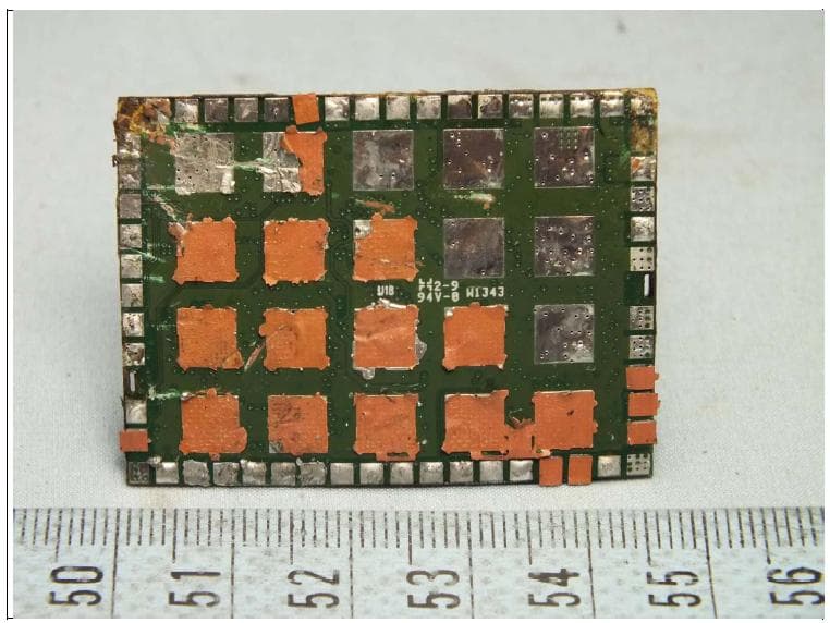
O4D-IC400
Jul 01, 2014WisReed Module
Equipment Class
DTS - Digital Transmission System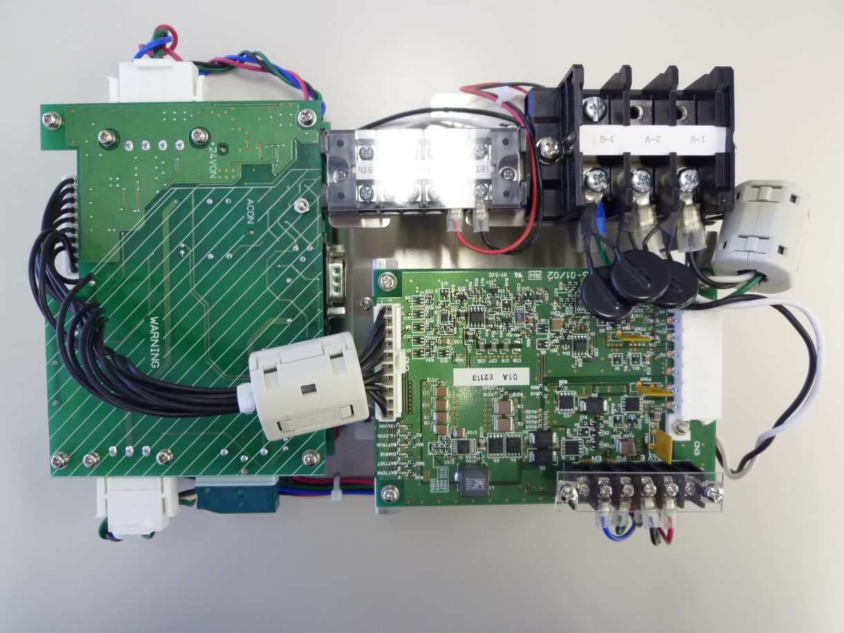
O4D-2012-002-SNB
Dec 11, 2012Concentrator / Relay Equipment (Networking Product)
Equipment Class
DTS - Digital Transmission System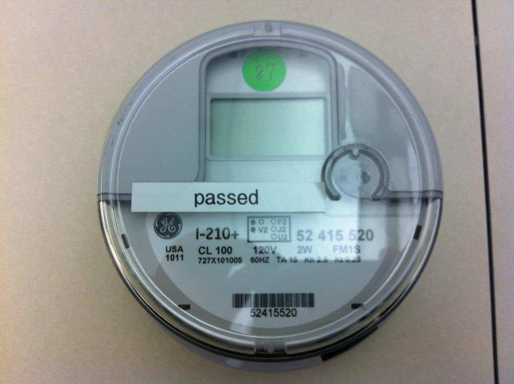
O4D-2012-001-SNB
Sep 03, 2012Communication Module
Equipment Class
DTS - Digital Transmission System