O4G7270100Indoor Bike Computer
Dayton Industrial Co., Ltd.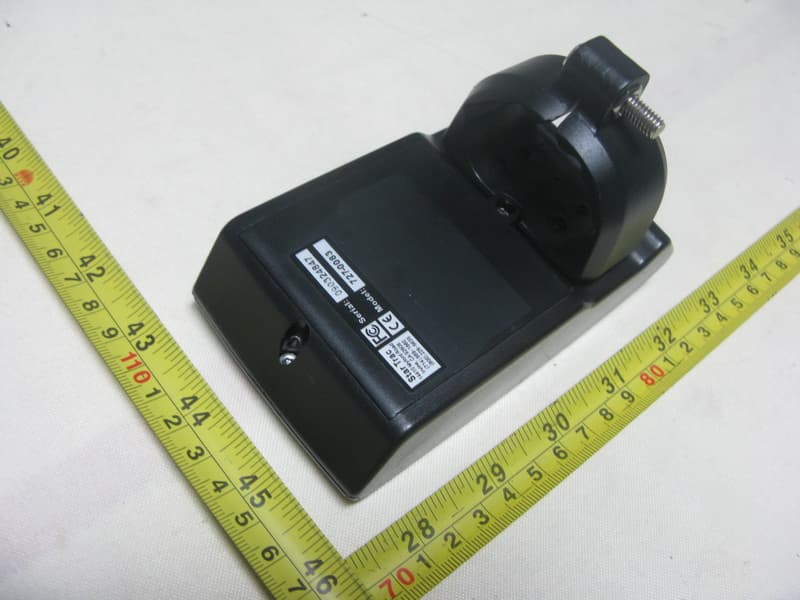
Click to zoom
Application Details
- Equipment Class
- DXT - Part 15 Low Power Transceiver, Rx Verified
- Date of Grant
- Feb 07, 2010
- Application Purpose
- Original Equipment
- Date of Application
- Feb 07, 2010
- Equipment Note
- Indoor Bike Computer
- Frequency Range
- 2466.00000000 - 2466.00000000
- Company
- Dayton Industrial Co., Ltd.
- Country
- Hong Kong
Documents & Files
Document Text
Text extracted from the exhibit documents filed with the FCC. Open a document above to read the original.
Users Manual
Spinning ® Computer User Manual Installation, Service and Instructor Education 01 02 03 05 06 07 08 10 11 12 15 18 19 20 21 22 23 25 FCC Regulatory Statements Parts List Marketing Statement Regarding Heart Rate Specifications How it Works Computer Window and Buttons Installing or Replacing Batteries Do I need to Re-sync? Testing for RPM Syncing Mode Setup Mode Installation of Cadence Sensor and Magnet – All Spinners ® Mounting Computer On Handlebars - Spinner ® V Mounting Computer On Handlebars - Sport / Fit / Elite Mounting Computer On Handlebars - Pro 7070 / Elite 7080 / NXT 7090 Maintenance Checklist FAQ’s and Troubleshooting Spinning ® Instructor Education Table of Contents FCC Regulatory Statements 1. This device complies with Part 15 of the FCC Rules. Operation is subject to the following two conditions: (1) this device may not cause harmful interference, and (2) this device must accept any interference received, including interference that may cause undesired operation. 2. Changes or modifications not expressly approved by Star Trac could void the user’s authority to operate the equipment. 1 Parts List Part Number for re-order QuantityDescription 727-0100 Spinning ® Computer Kit 1Spinning ® Computer 727-0093-KT Mounting Bracket Kit 1Mounting Bracket 1Spinner ® V Mounting Bracket Insert 1Mounting Insert for open handlebars 727-0084-KT1Cadence Sensor 727-00941Cadence Magnet N/A1AA Panasonic Batteries N/A1Spinning ® Computer Manual N/A1M5 Allen Assembly Tool N/A1M2 Allen Assembly Tool N/A1M6x30 Computer Clamp Screw for Rhino Horn Before installing the Spinning ® Computer, verify that all the parts needed for mounting on your bikes are included. If any of the items are missing, call StarTrac at 800-503-1221 or 1-714-669-1660 to order a replacement kit. 2 Marketing Statement Regarding Heart Rate Marketing Statement Regarding Heart Rate Acquisition on the Star Trac Spinning ® Computer: Star Trac takes the acquisition and accuracy of heart rate very seriously and has developed a system to perform to the best ability that technology will allow. Star Trac has engineered a product that has taken every precaution possible to acquire an accurate heart rate signal as well as eliminate “crosstalk” interference that may be caused by other monitors being placed too close together. To achieve the best possible results from your Spinning ® Computer, please abide by the following important parameters: 1) Users must wear either a Coded Transmitters (such as Polar© T61, Polar© T31C or Polar© WearLink ® ) or an Ant+ compatible transmitter when operating the Spinner ® bike with the Spinning ® Computer. Only will the Transmitter allow a “one to one” relationship with the Spinning ® Computer and will minimize potential “crosstalk” interference. If users wear non-coded straps, there is significantly increased potential for “crosstalk” which will cause erratic heart rate display, loss of heart rate display and significantly reduce the consistency of accurate heart rate reporting. 2) Bikes should be spaced so that the side-to-side distance from the Spinning ® Computer on one bike and the Spinning ® Computer on bikes to the left or right is at least 36 inches (91.4 cm). In addition, the distance from the bottom of the Spinning ® Computer on one bike to the seat of the bike in front of it (where another rider and his her transmitter would be seated) should be at least 24 inches (61 cm) in order to significantly reduce chances for interference. See the diagram on page 5 regarding bike layout. 3 3) In order for the computer to display the user’s heart rate the riders must lean into the display (within 10 inches) during the first 30 seconds of the ride. and wait for the HR to display. During this time the computer creates a one to one relationship with the rider’s heart rate strap and this insures that no outside signals will interfere with the riders data once they return to their seated position. 4) Calorie calculations are displayed as a summary only. 5) Cell phones, televisions, speakers and other electronic devices can cause interference with the operation if they are in close proximity to the Spinning ® Computer and/or transmitter. If there are any questions regarding operation or usage of the Spinning ® Computer, please contact Star Trac Customer Support at 800-503-1221 or 1-714-669-1660. 4 Specifications Computer: Heart Rate Range: Battery: Battery life expectancy: Cadence Sensor: Battery: Battery life expectancy: Distance to magnet: Approximately 30” from computer to users HR chest strap Qty 4 each AA Alkaline 1 year (depending on use and backlight usage) Lithium CR2032 Approximately 1 year in a commercial enviornment (depending on use) Approximately 5mm 5 At least 36 inches (91.4 cm) At least 24 inches (61 cm) How it Works How does the Spinning ® computer work? The Spinning ® computer displays heart rate, RPM (speed), total distance and elapsed time. • The heart rate information is received from an Ant+ or Polar ® compatible heart rate strap worn by the person riding the Spinning ® Bike. The HR strap sends a radio signal to the computer and the computer displays the person’s heart rate. If any other strap is used it will not display the heart rate. The computer and heart rate strap must be within range of each other and no other heart rate strap can be within this imaginary circle. The range is approximately 30 inches from the computer. •The RPM signal is transmitted by the cadence sensor sending the RPM to the computer. Each time the magnet on the flywheel passes the cadence sensor it records one revolution and as it counts the revolutions it sends this number to the computer. 6 RPMHeart rate Computer Window and Buttons Start pedaling then press any button to turn on the Spinning ® Computer; the following data will be displayed: HR- Displays the Heart Rate of the user when wearing a compatible Polar ® HR telemetry strap in beats per minute. RPM- Shows the pedaling speed of the user in revolutions per m…
Text truncated - open the document above for the full version.
External Photos
Neutron Engineering Inc. Project No.: 1001C019 Page 2 of 6 1001C019 1001C019 Neutron Engineering Inc. Project No.: 1001C019 Page 2 of 6 1001C019 1001C019
ID Label/Location Info
PDF created with pdfFactory trial version www.pdffactory.com
Internal Photos
Neutron Engineering Inc. Project No.: 1001C019 Page 3 of 6 1001C019 1001C019 Neutron Engineering Inc. Project No.: 1001C019 Page 3 of 6 1001C019 1001C019 Neutron Engineering Inc. Project No.: 1001C019 Page 4 of 6 1001C019 1001C019 Neutron Engineering Inc. Project No.: 1001C019 Page 4 of 6 1001C019 1001C019 Neutron Engineering Inc. Project No.: 1001C019 Page 5 of 6 1001C019 1001C019 Neutron Engineering Inc. Project No.: 1001C019 Page 5 of 6 1001C019 1001C019 Neutron Engineering Inc. Project No.: 1001C019 Page 6 of 6 1001C019 1001C019 Neutron Engineering Inc. Project No.: 1001C019 Page 6 of 6 1001C019 1001C019
Test Report
Neutron Engineering Inc. Report No.: NEI-FCCP-1-1001C019 Page 2 of 37 Declaration Neutron represents to the client that testing is done in accordance with standard procedures as applicable and that test instruments used has been calibrated with the standards traceable to National Measurement Laboratory (NML) of R.O.C., or National Institute of Standards and Technology (NIST) of U.S.A. Neutron's reports apply only to the specific samples tested under conditions. It is manufacture’s responsibility to ensure that additional production units of this model are manufactured with the identical electrical and mechanical components. Neutronshall have no liability for any declarations, inferences o r generalizations drawn by the client or others from Neutron issued reports. Neutron’s reports must not be used by the client to claim product endorsement by the authorities or any agency of the Government. This report is the confidential property of the client. As a mutual protection to the clients, the public and Neutron-self, extracts from the test report shall not be reproduced except in full with Neutron’s authorized written approval. Neutron’s laboratory quality assurance procedures are in compliance with the ISO Guide 17025 requirements, and accredited by the conformity assessment authorities listed in this test report. Limitation For the use of the authority's logo is limited unless the Test Standard(s)/Scope(s)/Item(s) mentioned in this test report is (are) included in the conformity assessment authorities acceptance respective. Neutron Engineering Inc. Report No.: NEI-FCCP-1-1001C019 Page 3 of 37 Table of Contents Page 1 . CERTIFICATION 5 2 . SUMMARY OF TEST RESULTS 6 2.1 TEST FACILITY 7 2.2 MEASUREMENT UNCERTAINTY 7 3 . GENERAL INFORMATION 8 3.1 GENERAL DESCRIPTION OF EUT 8 3.2 DESCRIPTION OF TEST MODES 10 3.3 BLOCK DIGRAM SHOWING THE CONFIGURATION OF SYSTEM TESTED 11 3.4 DESCRIPTION OF SUPPORT UNITS 12 4 . EMC EMISSION TEST 13 4.1 CONDUCTED EMISSION MEASUREMENT 13 4.1.1 POWER LINE CONDUCTED EMISSION LIMITS 13 4.1.2 MEASUREMENT INSTRUMENTS LIST 13 4.1.3 TEST PROCEDURE 14 4.1.4 DEVIATION FROM TEST STANDARD 14 4.1.5 TEST SETUP 14 4.1.6 EUT OPERATING CONDITIONS 14 4.1.7 TEST RESULTS 15 4.2 RADIATED EMISSION MEASUREMENT 16 4.2.1 RADIATED EMISSION LIMITS 16 4.2.2 MEASUREMENT INSTRUMENTS LIST 17 4.2.3 TEST PROCEDURE 19 4.2.4 DEVIATION FROM TEST STANDARD 19 4.2.5 TEST SETUP 20 4.2.6 EUT OPERATING CONDITIONS 21 4.2.7 TEST RESULTS (BETWEEN 30 – 1000 MHz) 22 4.2.8 TEST RESULTS (ABOVE 1000 MHz) 24 4.2.9 SUMMARY OF TEST RESULTS OF FUNDAMENTAL FREQUENCIES (2400 – 2483.5MHz) 28 4.2.10 TEST RESULTS (Restricted Bands Requirements) 29 5 . BANDWIDTH TEST 31 5.1 MEASUREMENT INSTRUMENTS LIST 31 5.2 TEST PROCEDURE 31 5.3 DEVIATION FROM STANDARD 31 5.4 TEST SETUP 31 5.5 EUT OPERATION CONDITIONS 31 Neutron Engineering Inc. Report No.: NEI-FCCP-1-1001C019 Page 4 of 37 Table of Contents Page 5.6 TEST RESULTS 32 6 . ANTENNA CONDUCTED SPURIOUS EMISSION 33 6.1 APPLIED PROCEDURES / LIMIT 33 6.1.1 MEASUREMENT INSTRUMENTS LIST 33 6.1.2 TEST PROCEDURE 33 6.1.3 DEVIATION FROM STANDARD 33 6.1.4 TEST SETUP 33 6.1.5 EUT OPERATION CONDITIONS 34 6.1.6 TEST RESULTS 35 7 . EUT TEST PHOTO 37 Neutron Engineering Inc. Report No.: NEI-FCCP-1-1001C019 Page 5 of 37 1. CERTIFICATION E q u i p m e n t : Indoor Bike Computer Trade Name : N/A Model Name. : 727-0100 A p p l i c a n t : Dayton Industrial Co. Ltd. Date of Test : Jan. 07, 2010 ~ Jan. 20, 2010 T e s t I t e m : ENGINEERING SAMPLE Standards : FCC Part15, Subpart C(15.249)/ ANSI C63.4 : 2003 The above equipment has been tested and found compliance with the requirement of the relative standards by Neutron Engineering Inc. EMC Laboratory. The test data, data evaluation, and equipment configuration contained in our test report (Ref No. NEI-FCCP-1-1001C019) were obtained utilizing the test procedures, test instruments, test sites that has been accredited by the Authority of NVLAP and TAF according to the ISO-17025 quality assessment standard and technical standard(s). Neutron Engineering Inc. Report No.: NEI-FCCP-1-1001C019 Page 6 of 37 2. SUMMARY OF TEST RESULTS Test procedures according to the technical standards: FCC Part15, Subpart C (15.249) Standard Section Test Item Judgment Remark 15.207 Conducted Emission - N/A 15.209 Radiated emission PASS 15.249 Radiated Spurious Emission PASS NOTE: (1)” N/A” denotes test is not applicable in this Test Report Neutron Engineering Inc. Report No.: NEI-FCCP-1-1001C019 Page 7 of 37 2.1 TEST FACILITY The test facilities used to collect the test data in this report is C01/OS02 at the location of No.132-1, Lane 329, Sec. 2, Palian Road, Shijr City, Taipei, Taiwan. Neutron's test firm number is 95335 2.2 MEASUREMENT UNCERTAINTY The reported uncertainty of measurement y ± U,where expended uncertainty U is based on a standard uncertainty multiplied by a coverage factor of k=2,providing a level of confidence of approximately 95 %。 A. Conducted Measurement : Test Site Method Measurement Frequency Range U,(dB) NOTE C01 ANSI150 KHz ~ 30MHz 1.94 B. Radiated Measurement : Test Site Method Measurement Frequency Range Ant. H / V U,(dB) NOTE OS-01 ANSI30MHz ~ 200MHz V 3.82 30MHz ~ 200MHz H 3.60 200MHz ~ 1,000MHz V 3.86 200MHz ~ 1,000MHz H 3.94 OS-02 ANSI30MHz ~ 200MHz V 2.48 30MHz ~ 200MHz H 2.16 200MHz ~ 1,000MHz V 2.50 200MHz ~ 1,000MHz H 2.66 Neutron Engineering Inc. Report No.: NEI-FCCP-1-1001C019 Page 8 of 37 3. GENERAL INFORMATION 3.1 GENERAL DESCRIPTION OF EUT Equipment Indoor Bike Computer Trade Name N/A Model Name. 727-0100 OEM Brand/Model Name N/A Model Difference N/A Product Description The EUT is a Indoor Bike Computer. Product Type Low Power Communication Device Operation Frequency: 2466 MHz Modulation Type: GFSK Number Of Channel 1CH Antenna Designation: Printed antenna Antenna Gain(Peak) 1.03 dBi Output Power: 82.85 dBuV/m (AV Max.) Based on the application, features, or specification exhibited in User's Manual, the EUT is considered as an ITE/C…
Text truncated - open the document above for the full version.
Test Setup Photos
Neutron Engineering Inc. Report No.: NEI-FCCP-1-1001C019 Page 36 of 36 7. EUT TEST PHOTO Radiated Measurement Photos Neutron Engineering Inc. Report No.: NEI-FCCP-1-1001C019 Page 36 of 36 7. EUT TEST PHOTO Radiated Measurement Photos
Contact Information
Applicant
Wong Lap Fai(Project Manager)
Test Firm
BTL Inc.Andy Yeh
Technical Specifications
| # | Rule Parts | Frequency Range | Power Output |
|---|---|---|---|
| 1 | 15C | 2.47 GHz - 2.47 GHz | - |
Other Applications from Dayton Industrial Co., Ltd.
O4G387
May 19, 2026RS HMI Control
Equipment Class
DTS - Digital Transmission System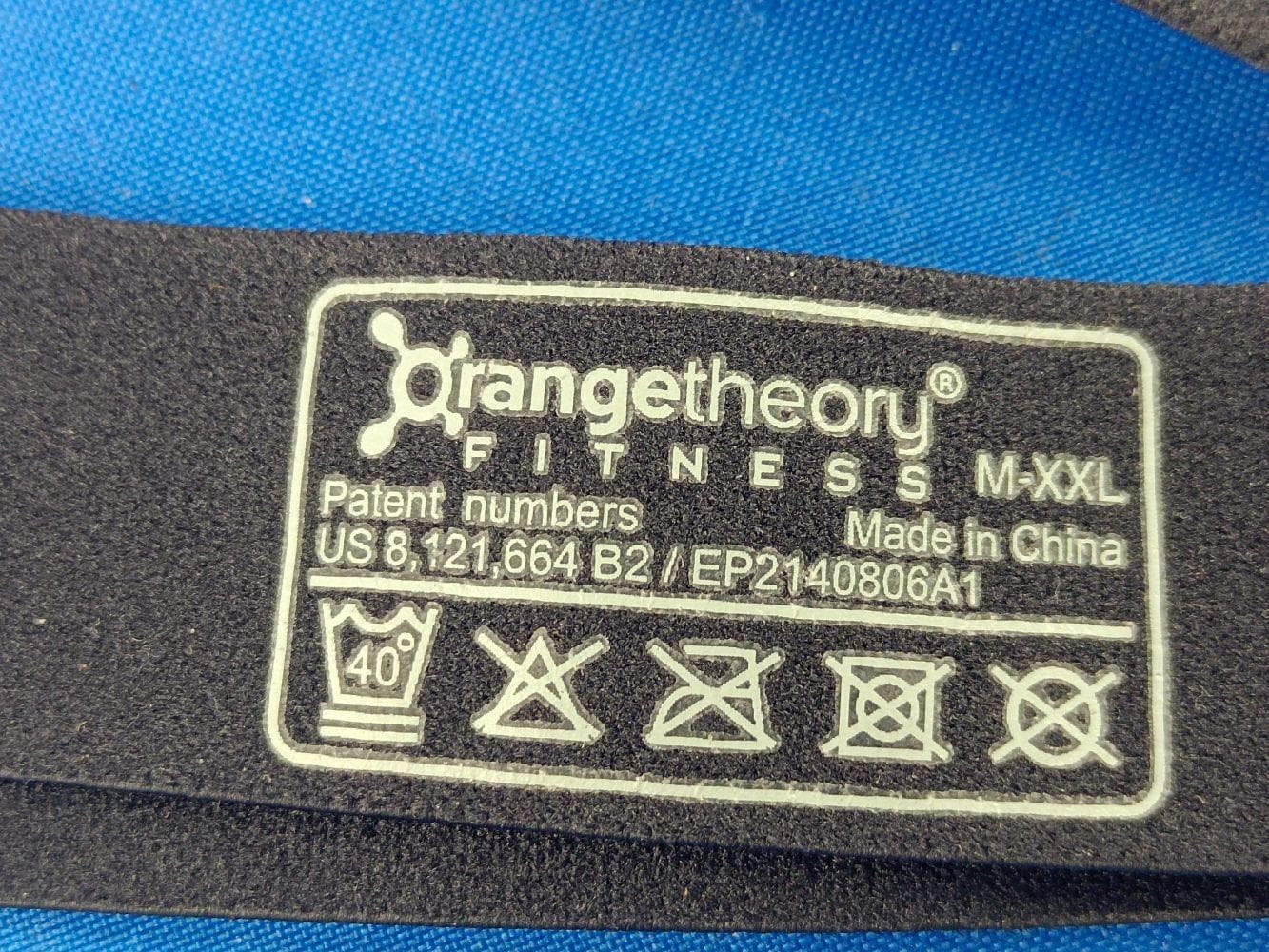
O4GHRM25
Feb 10, 2026LINK2CARE
Equipment Class
DTS - Digital Transmission System
O4GT3
Dec 16, 2023E-Bike HMI with BLE and ANT+
Equipment Class
DTS - Digital Transmission System
O4GTPMS
Jul 18, 2022SMART BIKE SENSOR with Bluetooth and ANT+ function.
Equipment Class
DTS - Digital Transmission System
O4GTCU2
Dec 28, 2020E-Bike controller with BLE and ANT+ function
Equipment Class
DXX - Part 15 Low Power Communication Device Transmitter