O4GHRMHW1GFabric Heart rate monitor
Dayton Industrial Co., Ltd.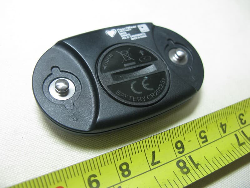
Click to zoom
Application Details
- Equipment Class
- DXX - Part 15 Low Power Communication Device Transmitter
- Date of Grant
- Mar 14, 2010
- Application Purpose
- Original Equipment
- Date of Application
- Mar 14, 2010
- Equipment Note
- Fabric Heart rate monitor
- Frequency Range
- 2457.00000000 - 2457.00000000
- Company
- Dayton Industrial Co., Ltd.
- Country
- Hong Kong
Documents & Files
Document Text
Text extracted from the exhibit documents filed with the FCC. Open a document above to read the original.
Users Manual
3_ Remove the cover and replace the battery with the positive side facing up. NOTE: Be careful not to damage or lose the o-ring gasket on the cover. 4_ Use a coin to twist the coverback into place. SWITCHING OFF THE SENSOR After 3 minutes of inactivity, all sensors automatically power off to conserve the battery. For more information about optional accessories, go to www.o-synce.com. You can also contact your o-synce dealer to purchase accessories. TECHNICAL FEATURES Physical size:65 x 38 x 11 mm Weight:25 g Water Resistance:10 m Transmission range: Approximately 3 m (9.8 ft) Battery: User-replaceable CR2032 (3 volts) Battery Life: Approximately 3 years (1 hour per day) HEART2feel free/X SOFT BELT The chest strap must be positioned around your chest. when correctly placed, it sends heart rate informa- tion to the watch. Located on the wrist, the watch displays the heart rate and provides various extra infor- mation (target zone, intensity of exer- cises) to manage and optimize your fitness and training. The soft belt will be connected with to clips at the sensor case. The rubber areas have to be placed on the skin (see photo below) USING THE HEART2feel free/X SOFT BELT The Heart2feel free sensor is using an analog RF communication, so no need for any pairing. You can use it like des- cribed in the manual of the matching product (MIXfree & MACRO free) The Heart2feel X sensor has to be pai- red like described in the manual for MIXpro & MACRO X – settings - pairing 1_ Connect the soft belt with the sensor on one side. Push one bottom of the heart rate sensor on the strap. 2_ Wet both sensors on the back (rub- ber area) of the heart rate monitor to create a strong connection between your chest and the transmitter (for extremely dry skin use some special gel) 3_ Wrap the strap around your chest and attach it to the other side of the heart rate monitor. NOTE: The o-synce logo should be right-side up. 4_ Bring the o-synce product you want to use within range (3 m) of the heart rate monitor. 5_ follow the instruction in user guide to connect and pair! O P E N CR2032 3V + NOTE:If or heart rate data does not appear or if you have erratic heart rate data, you may have to tighten the strap on your chest or warm up for 5–10 mi- nutes. If the problem persists, you may have to pair the sensors. Reapply moisture to the sensors. Use water, saliva, or electrode gel. Clean the sensors. Dirt and sweat residue on the sensor can interfere with heart rate si- gnals. Synthetic fabrics that rub or flap against the heart rate monitor can create static electricity that interferes with heart rate signals. NOTE:In cold conditions, wear appro- priate clothing to keep the heart rate monitor near your body temperature. Accuracy may be degraded by poor sensor contact, electrical interference and receiver distance from transmitter. Strong electromagnetic fields and some 2.4 GHz wireless sensors can interfere with your heart rate monitor. Sources of interference may include very high vol- tage power lines, electric motors, micro- wave ovens, 2.4 GHz cordless phones, and wireless LAN access points. After you move away from the source of inter- ference, your heart rate data should re- turn to normal. NOTE:Stay 10 m away from other ANT sensors while pairing. Bring the o-synce product within range (3 m) of the heart rate monitor while pairing. If the problem persists, replace the bat- tery. TO REPLACE THE BATTERY 1_ Locate the circular battery cover on the back of the sensor. 2_ Use a coin to twist the cover coun- er-clockwise until it is loose enough to remove. HEART2feel NOTES: THE MANUFACTURER IS NOT RESPONSIBLE FOR ANY RADIO OR TV INTERFERENCE CAUSED BY UNAUTHORIZED MODIFICATIONS TO THIS EQUIPMENT. SUCH MODIFICATIONS COULD VOID THE USER AUTHORITY TO OPERATE THE EQUIPMENT. NOTE: This equipment has been tested and found to comply with the limits for a Class B digital device, pursuant to Part 15 of the FCC Rules. These limits are designed to provide reasonable protection against harmful interference in a residential installation. This equipment generates uses and can radiate radio frequency energy and, if not installed and used in accordance with the instructions, may cause harmful interference to radio communications. However, there is no guarantee that interference will not occur in a particular installation. If this equipment does cause harmful interference to radio or television reception, which can be determined by turning the equipment off and on, the user is encouraged to try to correct the interference by one or more of the following measures: -- Reorient or relocate the receiving antenna. -- Increase the separation between the equipment and receiver. -- Connect the equipment into an outlet on a circuit different from that to which the receiver is corrected. -- Consult the dealer or experienced radio / TV technician for help. FCC ID: O4GHRM1G IC: 7666A-HRM1G MADE IN CHINA This device complies with part 15 of the FCC Rules. O p e r a t i o n i s s u b j e c t t o t h e f o l l o w i n g c o n d i t i o n s : (1) this device may not cause harmful interference, and (2) this device must accept any interference received, including interference that may cause undesired operation.
External Photos
Neutron Engineering Inc. Project No.: 1002C106 Page 2 of 6 1002C106 1002C106 Neutron Engineering Inc. Project No.: 1002C106 Page 2 of 6 1002C106 1002C106
Internal Photos
Neutron Engineering Inc. 1002C10 6 Project No.: 1002C106 Page 3 of 6 1002C10 6 Neutron Engineering Inc. 1002C10 6 Project No.: 1002C106 Page 4 of 6 1002C10 6 Neutron Engineering Inc. 1002C10 6 Project No.: 1002C106 Page 5 of 6 1002C10 6 Neutron Engineering Inc. 1002C10 6
Test Report
Neutron Engineering Inc. Report No.: NEI-FICP-1-1002C106 Page 2 of 36 Declaration Neutron represents to the client that testing is done in accordance with standard procedures as applicable and that test instruments used has been calibrated with the standards traceable to National Measurement Laboratory (NML) of R.O.C., or National Institute of Standards and Technology (NIST) of U.S.A. Neutron's reports apply only to the specific samples tested under conditions. It is manufacture’s responsibility to ensure that additional production units of this model are manufactured with the identical electrical and mechanical components. Neutronshall have no liability for any declarations, inferences o r generalizations drawn by the client or others from Neutron issued reports. Neutron’s reports must not be used by the client to claim product endorsement by the authorities or any agency of the Government. This report is the confidential property of the client. As a mutual protection to the clients, the public and Neutron-self, extracts from the test report shall not be reproduced except in full with Neutron’s authorized written approval. Neutron’s laboratory quality assurance procedures are in compliance with the ISO Guide 17025 requirements, and accredited by the conformity assessment authorities listed in this test report. Limitation For the use of the authority's logo is limited unless the Test Standard(s)/Scope(s)/Item(s) mentioned in this test report is (are) included in the conformity assessment authorities acceptance respective. Neutron Engineering Inc. Report No.: NEI-FICP-1-1002C106 Page 3 of 36 Table of Contents Page 1 . CERTIFICATION 5 2 . SUMMARY OF TEST RESULTS 6 2.1 TEST FACILITY 7 2.2 MEASUREMENT UNCERTAINTY 7 3 . GENERAL INFORMATION 8 3.1 GENERAL DESCRIPTION OF EUT 8 3.2 DESCRIPTION OF TEST MODES 10 3.3 BLOCK DIGRAM SHOWING THE CONFIGURATION OF SYSTEM TESTED 11 3.4 DESCRIPTION OF SUPPORT UNITS 12 4 . EMC EMISSION TEST 13 4.1 CONDUCTED EMISSION MEASUREMENT 13 4.1.1 POWER LINE CONDUCTED EMISSION LIMITS 13 4.1.2 MEASUREMENT INSTRUMENTS LIST 13 4.1.3 TEST PROCEDURE 14 4.1.4 DEVIATION FROM TEST STANDARD 14 4.1.5 TEST SETUP 14 4.1.6 EUT OPERATING CONDITIONS 14 4.1.7 TEST RESULTS 15 4.2 RADIATED EMISSION MEASUREMENT 16 4.2.1 RADIATED EMISSION LIMITS 16 4.2.2 MEASUREMENT INSTRUMENTS LIST 17 4.2.3 TEST PROCEDURE 20 4.2.4 DEVIATION FROM TEST STANDARD 20 4.2.5 TEST SETUP 21 4.2.6 EUT OPERATING CONDITIONS 22 4.2.7 TEST RESULTS (BETWEEN 30 – 1000 MHz) 23 4.2.8 TEST RESULTS (ABOVE 1000 MHz) 25 5 . BANDWIDTH TEST 29 5.1 MEASUREMENT INSTRUMENTS LIST 29 5.2 TEST PROCEDURE 29 5.3 DEVIATION FROM STANDARD 29 5.4 TEST SETUP 29 5.5 EUT OPERATION CONDITIONS 29 5.6 TEST RESULTS 30 6 . ANTENNA CONDUCTED SPURIOUS EMISSION 31 Neutron Engineering Inc. Report No.: NEI-FICP-1-1002C106 Page 4 of 36 Table of Contents Page 6.1 APPLIED PROCEDURES / LIMIT 31 6.1.1 MEASUREMENT INSTRUMENTS LIST 31 6.1.2 TEST PROCEDURE 31 6.1.3 DEVIATION FROM STANDARD 31 6.1.4 TEST SETUP 31 6.1.5 EUT OPERATION CONDITIONS 32 6.1.6 TEST RESULTS 33 7 . EUT TEST PHOTO 35 Neutron Engineering Inc. Report No.: NEI-FICP-1-1002C106 Page 5 of 36 1. CERTIFICATION E q u i p m e n t : Fabric Heart rate monitor Trade Name : N/A Model Name. : SHRM1G A p p l i c a n t : Dayton Industrial Co. Ltd. Date of Test : Feb. 23, 2010~ Mar. 01, 2010 T e s t I t e m : ENGINEERING SAMPLE Standards : FCC Part15, Subpart C(15.249)/ ANSI C63.4 : 2003; Canada RSS-210:2007 The above equipment has been tested and found compliance with the requirement of the relative standards by Neutron Engineering Inc. EMC Laboratory. The test data, data evaluation, and equipment configuration contained in our test report (Ref No. NEI-FICP-1-1002C106) were obtained utilizing the test procedures, test instruments, test sites that has been accredited by the Authority of NVLAP and TAF according to the ISO-17025 quality assessment standard and technical standard(s). Neutron Engineering Inc. Report No.: NEI-FICP-1-1002C106 Page 6 of 36 2. SUMMARY OF TEST RESULTS Test procedures according to the technical standards: FCC Part15, Subpart C (15.249) Canada RSS-210:2007 Canada FCC Test Item Judgment Remark 15.207 Conducted Emission - N/A A2.9(a) 15.209 Radiated emission PASS A2.9(a) 15.249 Radiated Spurious EmissionPASS NOTE: (1)” N/A” denotes test is not applicable in this Test Report Neutron Engineering Inc. Report No.: NEI-FICP-1-1002C106 Page 7 of 36 2.1 TEST FACILITY The test facilities used to collect the test data in this report is C01/OS02 at the location of No.132-1, Lane 329, Sec. 2, Palian Road, Shijr City, Taipei, Taiwan. Neutron's test firm number for FCC 95335 Neutron's test firm number for IC 4428A-1 2.2 MEASUREMENT UNCERTAINTY The reported uncertainty of measurement y ± U,where expended uncertainty U is based on a standard uncertainty multiplied by a coverage factor of k=2,providing a level of confidence of approximately 95 %。 A. Conducted Measurement : Test Site Method Measurement Frequency Range U,(dB) NOTE C01 ANSI150 KHz ~ 30MHz 1.94 B. Radiated Measurement : Test Site Method Measurement Frequency Range Ant. H / V U,(dB) NOTE OS-01 ANSI30MHz ~ 200MHz V 3.82 30MHz ~ 200MHz H 3.60 200MHz ~ 1,000MHz V 3.86 200MHz ~ 1,000MHz H 3.94 OS-02 ANSI30MHz ~ 200MHz V 2.48 30MHz ~ 200MHz H 2.16 200MHz ~ 1,000MHz V 2.50 200MHz ~ 1,000MHz H 2.66 Neutron Engineering Inc. Report No.: NEI-FICP-1-1002C106 Page 8 of 36 3. GENERAL INFORMATION 3.1 GENERAL DESCRIPTION OF EUT Equipment Fabric Heart rate monitor Trade Name N/A Model Name. SHRM1G OEM Brand/Model Name N/A Model Difference N/A Product Description The EUT is a Fabric Heart rate monitor. Product Type Low Power Communication Device Operation Frequency: 2457 MHz Modulation Type: GFSK Number Of Channel 1CH Antenna Designation: Printed antenna Antenna Gain(Peak) 0.76 dBi Output Power: 40.24 dBuV/m (AV Max.) Based on the application, features, or specification exhibited in User's Manual, the EUT is considered as an ITE/Computing Device. More detai…
Text truncated - open the document above for the full version.
Test Setup Photos
Neutron Engineering Inc. Report No.: NEI-FICP-1-1002C106 Page 35 of 36 7. EUT TEST PHOTO Radiated Measurement Photos TX Mode - Radiated emissions below 30MHz (Plot 1) TX Mode - Radiated emissions below 1000MHz (Plot 2) Neutron Engineering Inc. Report No.: NEI-FICP-1-1002C106 Page 35 of 36 7. EUT TEST PHOTO Radiated Measurement Photos TX Mode - Radiated emissions below 30MHz (Plot 1) TX Mode - Radiated emissions below 1000MHz (Plot 2) Neutron Engineering Inc. Report No.: NEI-FICP-1-1002C106 Page 36 of 36 Radiated Measurement Photos TX Mode - Radiated emissions Above 1000MHz (Plot 3)
Contact Information
Applicant
Wong Lap Fai(Project Manager)
Test Firm
BTL Inc.Andy Yeh
Technical Specifications
| # | Rule Parts | Frequency Range | Power Output |
|---|---|---|---|
| 1 | 15C | 2.46 GHz - 2.46 GHz | - |
Other Applications from Dayton Industrial Co., Ltd.
O4G387
May 19, 2026RS HMI Control
Equipment Class
DTS - Digital Transmission System
O4GHRM25
Feb 10, 2026LINK2CARE
Equipment Class
DTS - Digital Transmission System
O4GT3
Dec 16, 2023E-Bike HMI with BLE and ANT+
Equipment Class
DTS - Digital Transmission System
O4GTPMS
Jul 18, 2022SMART BIKE SENSOR with Bluetooth and ANT+ function.
Equipment Class
DTS - Digital Transmission System
O4GTCU2
Dec 28, 2020E-Bike controller with BLE and ANT+ function
Equipment Class
DXX - Part 15 Low Power Communication Device Transmitter