O4GIPDEKiPhone Dongle EK41800
Dayton Industrial Co., Ltd.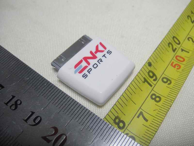
Click to zoom
Application Details
- Equipment Class
- DXX - Part 15 Low Power Communication Device Transmitter
- Date of Grant
- Jul 08, 2010
- Application Purpose
- Original Equipment
- Date of Application
- Jul 08, 2010
- Equipment Note
- iPhone Dongle EK41800
- Frequency Range
- 2457.00000000 - 2457.00000000
- Company
- Dayton Industrial Co., Ltd.
- Country
- Hong Kong
Documents & Files
Document Text
Text extracted from the exhibit documents filed with the FCC. Open a document above to read the original.
Users Manual
Quick Start Guide Introduction The Enki-Cycle system allows you to monitor your cycling workouts on your iPhone. The system is made up of three components. The first component is the two sensors which collect data. The first is a heart rate sensor and strap which measure your heart rate as you ride. The second is a combined speed and cadence sensor which measures how fast you are riding and the frequency or cadence you are pedaling at. The second component is the ANT+ accessory for your iPhone. This device allows the iPhone application to communicate with the sensor mentioned above. The third component is the Enki-Train iPhone application which is how you collect and view the information from the sensors on your iPhone. Step 1: Mount the Enki Sports Combined Speed and Cadence sensor to your bicycle 1. The best place to mount the sensor is the non- drive side chain stay. 2. Attach the supplied cadence magnet to the crank loosely with one of the supplied cable ties. Do not tighten the cable tie as you may need to adjust the position of the magnet. 3. Position the cadence sensor between the crank arm and the frame of the bicycle to ensure the magnet will passes closer than 0.5cm (¼ inch) of the cadence sensor. Ensure the magnet will not foul on the sensor in normal operation. 4. Tighten then trim both the magnet and sensor cable ties. It may be necessary to add some form of adhesive to the cadence magnet to ensure the magnet does not move in normal operation. This movement may be caused by shape of your crank or by excessive vibration. 5. Place the supplied rubber mount into the main part of the sensor. Loosely attach the main part of the sensor to your frame as shown. Do not tighten the cable ties fully at this time. 6. Attach the supplied speed magnet to your wheel as shown. Position the magnet to pass over the line marked on the sensor. Tighten the screw to ensure it will not move in normal operation. Do not over-tighten the screw as this may damage the threads on the magnet, your spoke or both. 7. Position the main sensor so magnet will pass the sensor at a distance of around 0.5cm (¼ inch). Take care to ensure the sensor will not foul on the magnet or other parts of the wheel. Tighten the cable ties as tight as possible. If these cable ties are loose the sensor may move and damage your wheel. Step 2: Plug your Enki Sports iPhone Accessory into your iPhone as shown • Take care not to apply excessive force to the accessory connector while connected to the iPhone as this could cause damage to the Enki Sports accessory, your iPhone or both devices • While intended to fit many different cases there will be a number of cases that do not allow the Enki Sports iPhone accessory to attach to the iPhone • Take care to protect the iPhone and Enki Sports accessory from water damage. Water damage will void the Enki Sports warranty and may effect other warranties. Step 3: Download the Enki Sports iPhone application: Unless you have already download the Enki Sports application from the App Store you will receive the following message: (replace with image of actual iPhone screen) Application Not Installed This accessory requires an application you do not have installed. Would you like to install it from the App Store? Click yes to this and you automatically be taken to the App Store page to download the Enki Sports iPhone application. Install the application. Step 4: Put on the heart rate sensor as shown Some users may need to apply a little moisture to the electrodes of the heart rate sensor strap to ensure a good connection. In normal operation perspiration will ensure an excellent connection is maintained. Enki Sports heart rate sensors are compatible with NuMetrex heart monitoring clothing ( http://www.numetrex.com/) Step 5: Launch application Step 6: Pair Sensors Open the Settings tab in the application Select the Sport Settings button Add a new sport mode by clicking the plus button in the top right of the screen Select cycling from the selector wheel Name the mode (after the bike type for example) Add a new sensor by clicking the plus button in the top right of the screen Select Heart Rate from the selector wheel Elements on the screen will go grey while the application searches for the sensor. After the sensor is found it will be added to the table of sensors. Activate the Combined Speed and Cadence Sensor by ensuring the magnets pass the sensors a number of times. A good way to do this is lifting the rear wheel of the bicycle and rotating the cranks a few times by hand. The sensor automatically goes to sleep after a period of time with the wheel and crank not rotating to save battery life. Add a new sensor by clicking the plus button in the top right of the screen Select Combined Speed and Cadence from the selector wheel Elements on the screen will go grey while the application searches for the sensor. After the sensor is found it will be added to the table of sensors. If you have a power meter activate your power meter Add a new sensor by clicking the plus button in the top right of the screen Select Power from the selector wheel Elements on the screen will go grey while the application searches for the sensor. After the sensor is found it will be added to the table of sensors. FCC ID: O4GIPDEK IC: 7666A-IPDEK FCC Statement This equipment has been tested and found to comply with the limits for a Class B digital device, pursuant to part 15 of the FCC rules. These limits are designed to provide reasonable protection against harmful interference in a residential installation. This equipment generates, uses and can radiate radio frequency energy and, if not installed and used in accordance with the instructions, may cause harmful interference to radio communications. However, there is no guarantee that interference will not occur in a particular installation. If this equipment does cause harmful interference to radio or television reception, which can be determined by turning the equipment off an…
Text truncated - open the document above for the full version.
External Photos
Neutron Engineering Inc. Project No.: 1006C003 Page 2 of 5 1006C003 1006C003 Neutron Engineering Inc. Project No.: 1006C003 Page 2 of 5 1006C003 1006C003
Internal Photos
Neutron Engineering Inc. Project No.: 1006C003 Page 3 of 5 1006C003 1006C003 Neutron Engineering Inc. Project No.: 1006C003 Page 3 of 5 1006C003 1006C003 Neutron Engineering Inc. Project No.: 1006C003 Page 4 of 5 1006C003 1006C003 Neutron Engineering Inc. Project No.: 1006C003 Page 4 of 5 1006C003 1006C003 Neutron Engineering Inc. Project No.: 1006C003 Page 5 of 5 1006C003
Test Report
Neutron Engineering Inc. Report No.: NEI-FICP-1-1006C003 Page 2 of 33 Declaration Neutron represents to the client that testing is done in accordance with standard procedures as applicable and that test instruments used has been calibrated with the standards traceable to National Measurement Laboratory (NML) of R.O.C., or National Institute of Standards and Technology (NIST) of U.S.A. Neutron's reports apply only to the specific samples tested under conditions. It is manufacture’s responsibility to ensure that additional production units of this model are manufactured with the identical electrical and mechanical components. Neutron shall have no liability for any declarations, inferences o r generalizations drawn by the client or others from Neutron issued reports. Neutron’s reports must not be used by the client to claim product endorsement by the authorities or any agency of the Government. This report is the confidential property of the client. As a mutual protection to the clients, the public and Neutron-self, extracts from the test report shall not be reproduced except in full with Neutron’s authorized written approval. Neutron’s laboratory quality assurance procedures are in compliance with the ISO Guide 17025 requirements, and accredited by the conformity assessment authorities listed in this test report. Limitation For the use of the authority's logo is limited unless the Test Standard(s)/Scope(s)/Item(s) mentioned in this test report is (are) included in the conformity assessment authorities acceptance respective. Neutron Engineering Inc. Report No.: NEI-FICP-1-1006C003 Page 3 of 33 Table of Contents Page 1 . CERTIFICATION 5 2 . SUMMARY OF TEST RESULTS 6 2.1 TEST FACILITY 7 2.2 MEASUREMENT UNCERTAINTY 7 3 . GENERAL INFORMATION 8 3.1 GENERAL DESCRIPTION OF EUT 8 3.2 DESCRIPTION OF TEST MODES 9 3.3 BLOCK DIGRAM SHOWING THE CONFIGURATION OF SYSTEM TESTED 10 3.4 DESCRIPTION OF SUPPORT UNITS 11 4 . EMC EMISSION TEST 12 4.1 CONDUCTED EMISSION MEASUREMENT 12 4.1.1 POWER LINE CONDUCTED EMISSION LIMITS 12 4.1.2 MEASUREMENT INSTRUMENTS LIST 12 4.1.3 TEST PROCEDURE 13 4.1.4 DEVIATION FROM TEST STANDARD 13 4.1.5 TEST SETUP 13 4.1.6 EUT OPERATING CONDITIONS 13 4.1.7 TEST RESULTS 14 4.2 RADIATED EMISSION MEASUREMENT 15 4.2.1 RADIATED EMISSION LIMITS 15 4.2.2 MEASUREMENT INSTRUMENTS LIST 16 4.2.3 TEST PROCEDURE 17 4.2.4 DEVIATION FROM TEST STANDARD 17 4.2.5 TEST SETUP 18 4.2.6 EUT OPERATING CONDITIONS 19 4.2.7 TEST RESULTS (BETWEEN 30 – 1000 MHz) 20 4.2.8 TEST RESULTS (ABOVE 1000 MHz) 22 5 . BANDWIDTH TEST 26 5.1 MEASUREMENT INSTRUMENTS LIST 26 5.2 TEST PROCEDURE 26 5.3 DEVIATION FROM STANDARD 26 5.4 TEST SETUP 26 5.5 EUT OPERATION CONDITIONS 26 5.6 TEST RESULTS 27 6 . ANTENNA CONDUCTED SPURIOUS EMISSION 28 Neutron Engineering Inc. Report No.: NEI-FICP-1-1006C003 Page 4 of 33 Table of Contents Page 6.1 APPLIED PROCEDURES / LIMIT 28 6.1.1 MEASUREMENT INSTRUMENTS LIST 28 6.1.2 TEST PROCEDURE 28 6.1.3 DEVIATION FROM STANDARD 28 6.1.4 TEST SETUP 28 6.1.5 EUT OPERATION CONDITIONS 29 6.1.6 TEST RESULTS 30 7 . EUT TEST PHOTO 31 Neutron Engineering Inc. Report No.: NEI-FICP-1-1006C003 Page 5 of 33 1. CERTIFICATION E q u i p m e n t : iPhone Dongle EK41800 Trade Name : N/A Model Name. : EK41800 A p p l i c a n t : Dayton Industrial Co. Ltd. Date of Test : Jun. 02, 2010~ Jun. 08, 2010 T e s t I t e m : ENGINEERING SAMPLE Standards : FCC Part15, Subpart C(15.249)/ ANSI C63.4 : 2003; Canada RSS-210:2007 The above equipment has been tested and found compliance with the requirement of the relative standards by Neutron Engineering Inc. EMC Laboratory. The test data, data evaluation, and equipment configuration contained in our test report (Ref No. NEI-FICP-1-1006C003) were obtained utilizing the test procedures, test instruments, test sites that has been accredited by the Authority of NVLAP and TAF according to the ISO-17025 quality assessment standard and technical standard(s). Neutron Engineering Inc. Report No.: NEI-FICP-1-1006C003 Page 6 of 33 2. SUMMARY OF TEST RESULTS Test procedures according to the technical standards: FCC Part15, Subpart C (15.249) Canada RSS-210:2007 Canada FCC Test Item Judgment Remark 15.207 Conducted Emission - N/A A2.9(a) 15.209 Radiated emission PASS A2.9(a) 15.249 Radiated Spurious EmissionPASS NOTE: (1)” N/A” denotes test is not applicable in this Test Report Neutron Engineering Inc. Report No.: NEI-FICP-1-1006C003 Page 7 of 33 2.1 TEST FACILITY The test facilities used to collect the test data in this report is DG-C03/CB03 at the location of No.3,Jinshagang 1st Road, ShiXia, Dalang Town, Dong Guan, China.523792 Neutron's test firm number for FCC 319330 Neutron's test firm number for IC 4428B-1 2.2 MEASUREMENT UNCERTAINTY Where relevant, the following measurement uncertainty levels have been estimated for tests performed on the EUT as specified in CISPR 16-4-2: The reported uncertainty of measurement y ± U,where expended uncertainty U is based on a standard uncertainty multiplied by a coverage factor of k=2,providing a level of confidence of approximately 95 %。 A. Conducted Measurement : Test Site Method Measurement Frequency Range U,(dB) NOTE DG-C03 CISPR 150 KHz ~ 30MHz 1.94 B. Radiated Measurement : Test Site Method Measurement Frequency Range Ant. H / V U,(dB) NOTE 30MHz ~ 200MHz V 3.82 30MHz ~ 200MHz H 3.60 200MHz ~ 1,000MHz V 3.86 CB03 CISPR 200MHz ~ 1,000MHz H 3.94 Neutron Engineering Inc. Report No.: NEI-FICP-1-1006C003 Page 8 of 33 3. GENERAL INFORMATION 3.1 GENERAL DESCRIPTION OF EUT Equipment iPhone Dongle EK41800 Trade Name N/A Model Name. EK41800 OEM Brand/Model Name N/A Model Difference N/A Product Description The EUT is a iPhone Dongle EK41800. Product Type Low Power Communication Device Operation Frequency: 2457 MHz Modulation Type: GFSK Number Of Channel 1CH Antenna Designation: Integral antenna Antenna Gain(Peak) 2.12 dBi Output Power: 93.24 dBuV/m (AV Max.) Based on the application, features, or specification exhibited in User's Manual, the EUT is consider…
Text truncated - open the document above for the full version.
Test Setup Photos
Neutron Engineering Inc. Report No.: NEI-FICP-1-1006C003 Page 31 of 33 7. EUT TEST PHOTO Radiated Measurement Photos 9K~30MHz Neutron Engineering Inc. Report No.: NEI-FICP-1-1006C003 Page 31 of 33 7. EUT TEST PHOTO Radiated Measurement Photos 9K~30MHz Neutron Engineering Inc. Report No.: NEI-FICP-1-1006C003 Page 32 of 33 Radiated Measurement Photos 30M~1000MHz Neutron Engineering Inc. Report No.: NEI-FICP-1-1006C003 Page 32 of 33 Radiated Measurement Photos 30M~1000MHz Neutron Engineering Inc. Report No.: NEI-FICP-1-1006C003 Page 33 of 33 Radiated Measurement Photos Above 1000MHz Neutron Engineering Inc. Report No.: NEI-FICP-1-1006C003 Page 33 of 33 Radiated Measurement Photos Above 1000MHz
Contact Information
Applicant
Wong Lap Fai(Project Manager)
Test Firm
BTL Inc.Daisy Dai
Technical Specifications
| # | Rule Parts | Frequency Range | Power Output |
|---|---|---|---|
| 1 | 15C | 2.46 GHz - 2.46 GHz | - |
Other Applications from Dayton Industrial Co., Ltd.
O4G387
May 19, 2026RS HMI Control
Equipment Class
DTS - Digital Transmission System
O4GHRM25
Feb 10, 2026LINK2CARE
Equipment Class
DTS - Digital Transmission System
O4GT3
Dec 16, 2023E-Bike HMI with BLE and ANT+
Equipment Class
DTS - Digital Transmission System
O4GTPMS
Jul 18, 2022SMART BIKE SENSOR with Bluetooth and ANT+ function.
Equipment Class
DTS - Digital Transmission System
O4GTCU2
Dec 28, 2020E-Bike controller with BLE and ANT+ function
Equipment Class
DXX - Part 15 Low Power Communication Device Transmitter