O4GJOULE1Bike Computer
Dayton Industrial Co., Ltd.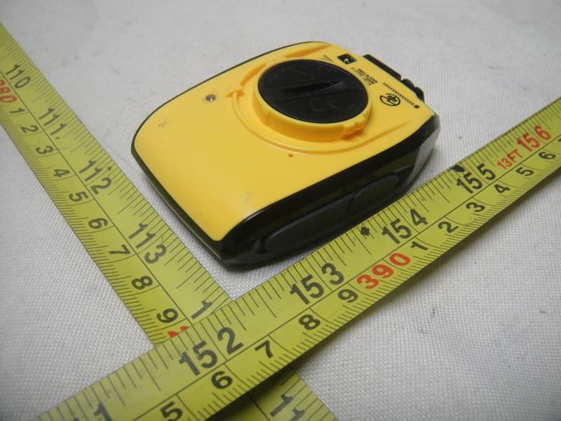
Click to zoom
Application Details
- Equipment Class
- DXT - Part 15 Low Power Transceiver, Rx Verified
- Date of Grant
- Nov 06, 2011
- Application Purpose
- Original Equipment
- Date of Application
- Nov 06, 2011
- Equipment Note
- Bike Computer
- Frequency Range
- 2457.00000000 - 2457.00000000
- Company
- Dayton Industrial Co., Ltd.
- Country
- Hong Kong
Documents & Files
Document Text
Text extracted from the exhibit documents filed with the FCC. Open a document above to read the original.
Users Manual
Joule 1.0 Quickstart Guide | Guía de usuario | Mode d’emploi | Benutzerhandbuch | Manuale dell’utente | Gebruikershandleiding | INT 2 11:31 00 INT A 0.00.0 NAVIGATION OVERVIEW [ENTER] button * Selects item in menu * Hold for 3 seconds - Go to Menu * Hold for 3 seconds in Menus - Go to Dashboard Shifts “arrow” counterclockwise among the data fields Shifts “arrow” clockwise among the data fields Press to mark intervals [PLUS] button [MINUS] button [INTERVAL] button INTRODUCTION Joule is compatible with any ANT+ compatible power meter, speed sensor, cadence sensor, or heart rate sensor. For a complete user guide, please visit www.cycleops.com Time Normalized Power Heart rate Speed Cadence Current percent grade Distance Kilojoules Watts/Kg Power ICONS DRAFT/FOR DEANNA/ 10 07 11 /JOULE 1/QUICKSTART BUTTONSFUNCTION 11:31 123.5 A 194597 DASHBOARDS INTERVALS Intervals are useful for viewing ride data specific to a section of your ride, such as a ball or other period of high intensity riding. INT Press 1x Press 1xPress 1x DASHBOARD 1 [PLUS][PLUS] Press 1xPress 1x [PLUS][PLUS] Press 1xPress 1x [PLUS][PLUS] [ENTER] INT Press 2x [ENTER] INT Press 3x [ENTER] DRAFT/FOR DEANNA/ 10 07 11 /JOULE 1/QUICKSTART 11:31 123.5 A 17.832.5 11:31 123.5 A 849 KJride 1:23:31 11:31 1235 105 A DASHBOARD 2 11:31 -5.21:23:31 A 17.832.5 DASHBOARD 3 11:31 A 21.59 11:31 A 10287 alt-ftft-gain 23652 849 KJride 1:23:31 11:31 A 129162 11:31 A 95129 Each Dashboard displays five customizable (via PowerAgent) metrics. Distance Watts Distance Current Cadence Ride distance Current Power Max HR Distance Total Ascent Current HR Ride Distance Current Cadence Speed Percent Grade Current Cadence Percent Grade Work Work Altitude Average Speed Max Watts Ride Time Max Speed Max Speed Ride Time Current Speed Ride Distance Current HR Max Cadence Current Speed Ride Time Avg Watts 432 25.3 432 Avg/Max Bar Graph 25.3 Avg Speed 432 25.3 147 Ride Time 1235 105 147 1235 105 147 Avg HR Avg Cadence 253 -5.21:23:31 253 -5.21:23:31 253 MILES INTERVALS Intervals are useful for viewing ride data specific to a section of your ride, such as a ball or other period of high intensity riding. [INTERVAL] INT INT Press & Hold 3 sec. to go to Interval Mode [INTERVAL] Press & Hold 3 sec. to go back to Ride Mode 3 oF 6 MENU:SENSOR DRAFT/FOR DEANNA/ 10 07 11 /JOULE 1/QUICKSTART other sensors 60' or 18m SETTING UP SENSORS Joule 1.0 is compatible with many ANT+ sensors, each having a unique code. START RIDE: Begin your ride by... 2 11:31 00 INT A Press • [ENTER] & hold for 3 sec. to go to Menu. Press + [Plus] twice more to go to Sensor menu INT DASHBOARDMENU>SENSORSENSOR SUBMENU RESULT BACK TO MENU RE-ZERO PAIRING FIND BIKE WHEEL CIRCUMFERENCE INT Press 3 sec Press 2 X [PLUS] [ENTER] SWITCH->MENU HOLD 3 1 oF 5 BIKE1:FIND FIND 2 oF 5 BIKE1:PAIR PAIR all pair: power pair: h-r pair: cadence pair: speed 3 oF 5 BIKE1:ZERO 4 oF 5 BIKE1:WHEEL 5 oF 5 back ->menu back ->menu • [ENTER] • [ENTER] • [ENTER] • [ENTER] Re-zero? Press • [ENTER] on any Finds bike Performs Manual Zero set circumf <-+> Press + or - for your circumference, then press Sets circumference of wheel Goes back to main menu Pairs all sensors Pairs power sensor Pairs heart rate sensor Pairs cadence sensor Pairs speed sensor Press • [ENTER] to go to any sensor sub-menu [ENTER] RIDE MODEINTERVAL MODE Displays data for current interval Add copy.... ENTIRE RIDE Add copy... INTERVAL 2 INTERVAL 1 UP TO 99 INTERVALS 11:31 A 2 11:31 INT A DOWNLOAD Install PowerAgent software from www.cycleops.com/poweragent to download ride data INSTALLATION DRAFT/FOR DEANNA/ 10 07 11 /JOULE 1/QUICKSTART MENU Enter Menu to review ride history, pair sensors, use the workout function, and configure the device. INT [ENTER] Press & Hold 3 sec. Press 1x to go forward Press 1x to go backward [PLUS] [MINUS] 11:31 A RIDE FROM DASHBOARD 1 oF 6 MENU:RIDE 2 oF 6 MENU:HISTORY 4 oF 6 MENU:WORKOUT 3 oF 6 MENU:SENSOR 5 oF 6 MENU:DEVICE 6 oF 6 back:->dash PAUSE SAVE LAST RIDE LAST 1 WK LAST 2 WK LAST 4 WK BIKE1: FIND BIKE1: PAIR BIKE1: ZERO WO: DISTANCE WO: TIMER DEV: TRIP DEV: ALTI DEV: CLOCK BACK->DASH DEV: UNITS DEV: LANGUAGE BACK->MENU BIKE1: WHEEL BACK->MENU WO: KJ BACK->MENU ALL RIDES PICK RIDE BACK->MENU CLEAR BACK->MENU Press • [ENTER] to select item Press + [Plus] to move in Menu INT [PLUS] [ENTER] Press • [ENTER] to select sub-menu [ENTER] HISTORY SENSOR WORKOUT DEVICE BACK TO DASHBOARD INT MicroUSB USB HANDLEBAR MOUNT INT INT O-Rings: Crisscross under stem, latch on hooks OR Zip tie around stem, through slots STEM MOUNT INT INT GO FOR A RIDE FCC statement NOTE: THE MANUFACTURER IS NOT RESPONSIBLE FOR ANY RADIO OR TV INTERFERENCE CASUSED BY UNAUTHORIZED MODIFICATIONS TO THIS EQUIPMENT. SUCH MODIFICATIONS COULD VOID THE USER AUTHORITY TO OPERATE THE EQUIPMENT. NOTE: This equipment has been tested and found to comply with the limits for a Class B digital device, pursuant to Part 15 of the FCC Rules. These limits are designed to provide reasonable protection against harmful interference in a residential installation. This equipment generates uses and can radiate radio frequency energy and , if not installed and used in accordance with the instructions, may cause harmful interference to radio communications. However, there is no guarantee that interference will not occur in a particular installation. If this equipment does cause harmful interference to radio or television reception, which can be determined by turning the equipment off and on, the user is encouraged to try to correct the interference by one or more the following measures: Reorient or relocate the receiving antenna Increase the separation between the equipment and receiver Connect the equipment into an outlet on a circuit different from that to which the receiver is corrected Consult the dealer or experience radio / TV technician for help Canada Statement IC: 7666A‐JOULE1 This Device complies with RSS‐210 of IC Rules; Operation is subject to the following two conditions: …
Text truncated - open the document above for the full version.
External Photos
Neutron Engineering Inc. Project No.: 1110C175 Page 2 of 7 1110C175 1110C175 Neutron Engineering Inc. Project No.: 1110C175 Page 2 of 7 1110C175 1110C175
Internal Photos
Neutron Engineering Inc. Project No.: 1110C175 Page 3 of 7 1110C175 1110C175 Neutron Engineering Inc. Project No.: 1110C175 Page 3 of 7 1110C175 1110C175 Neutron Engineering Inc. Project No.: 1110C175 Page 4 of 7 1110C175 1110C175 Neutron Engineering Inc. Project No.: 1110C175 Page 4 of 7 1110C175 1110C175 Neutron Engineering Inc. Project No.: 1110C175 Page 5 of 7 1110C175 1110C175 Neutron Engineering Inc. Project No.: 1110C175 Page 5 of 7 1110C175 1110C175 Neutron Engineering Inc. Project No.: 1110C175 Page 6 of 7 1110C175 1110C175 Neutron Engineering Inc. Project No.: 1110C175 Page 6 of 7 1110C175 1110C175 Neutron Engineering Inc. Project No.: 1110C175 Page 7 of 7 1110C175 1110C175 Neutron Engineering Inc. Project No.: 1110C175 Page 7 of 7 1110C175 1110C175
Test Report
Neutron Engineering Inc. Report No.: NEI-FICP-1-1110C175 Page 1 of 44 FCC/IC Radio Test Report FCC ID: O4GJOULE1 IC: 7666A-JOULE1 This report concerns (check one): Original Grant Class II Change Issued Date : Nov. 01, 2011 Project No. : 1110C175 Equipment : Bike Computer Model Name : JOULE 1.0 Applicant : Dayton Industrial Co. Ltd. Address : 2-12 Kwai Fat Road, 11- A Kwai Chung,New Territories, Hong Kong Manufacturer : Kendy Electronics (Dongguan) Co. Ltd. Address : Xingsi Huangtang Village, Hengli Town, Dongguan City, Guangdong Province, P.R. China Tested by: Neutron Engineering Inc. EMC Laboratory Date of Receipt: Oct. 24, 2011 Date of Test: Oct. 24, 2011 ~ Oct. 31, 2011 Testing Engineer : (Ivan Cao) Technical Manager : (Leo Hung) Authorized Signatory : (Steven Lu) Neutron Engineering Inc. No.3,Jinshagang 1st Road, ShiXia, Dalang Town, Dong Guan, China. TEL : (0769) 8318-3000 FAX : (0769) 8319-6000 Neutron Engineering Inc. Report No.: NEI-FICP-1-1110C175 Page 2 of 44 Declaration Neutron represents to the client that testing is done in accordance with standard procedures as applicable and that test instruments used has been calibrated with the standards traceable to National Measurement Laboratory (NML) of R.O.C., or National Institute of Standards and Technology (NIST) of U.S.A. Neutron's reports apply only to the specific samples tested under conditions. It is manufacture’s responsibility to ensure that additional production units of this model are manufactured with the identical electrical and mechanical components. Neutron shall have no liability for any declarations, inferences o r generalizations drawn by the client or others from Neutron issued reports. Neutron’s reports must not be used by the client to claim product endorsement by the authorities or any agency of the Government. This report is the confidential property of the client. As a mutual protection to the clients, the public and Neutron-self, extracts from the test report shall not be reproduced except in full with Neutron’s authorized written approval. Neutron’s laboratory quality assurance procedures are in compliance with the ISO Guide 17025 requirements, and accredited by the conformity assessment authorities listed in this test report. Limitation For the use of the authority's logo is limited unless the Test Standard(s)/Scope(s)/Item(s) mentioned in this test report is (are) included in the conformity assessment authorities acceptance respective. Neutron Engineering Inc. Report No.: NEI-FICP-1-1110C175 Page 3 of 44 Table of Contents Page 1 . CERTIFICATION 5 2 . SUMMARY OF TEST RESULTS 6 2.1 TEST FACILITY 7 2.2 MEASUREMENT UNCERTAINTY 7 3 . GENERAL INFORMATION 8 3.1 GENERAL DESCRIPTION OF EUT 8 3.2 DESCRIPTION OF TEST MODES 9 3.3 BLOCK DIGRAM SHOWING THE CONFIGURATION OF SYSTEM TESTED 10 3.4 DESCRIPTION OF SUPPORT UNITS 11 4 . EMC EMISSION TEST 12 4.1 CONDUCTED EMISSION MEASUREMENT 12 4.1.1 POWER LINE CONDUCTED EMISSION LIMITS 12 4.1.2 MEASUREMENT INSTRUMENTS LIST 12 4.1.3 TEST PROCEDURE 13 4.1.4 DEVIATION FROM TEST STANDARD 13 4.1.5 TEST SETUP 13 4.1.6 EUT OPERATING CONDITIONS 13 4.1.7 TEST RESULTS 14 4.2 RADIATED EMISSION MEASUREMENT 16 4.2.1 RADIATED EMISSION LIMITS 16 4.2.2 MEASUREMENT INSTRUMENTS LIST 17 4.2.3 TEST PROCEDURE 20 4.2.4 DEVIATION FROM TEST STANDARD 20 4.2.5 TEST SETUP 21 4.2.6 EUT OPERATING CONDITIONS 22 4.2.7 TEST RESULTS (BETWEEN 30 – 1000 MHz) 24 4.2.8 TEST RESULTS (ABOVE 1000 MHz) 28 4.2.9 TEST RESULTS (2400 – 2483.5 MHz) 34 5 . BANDWIDTH TEST 35 5.1 MEASUREMENT INSTRUMENTS LIST 35 5.2 TEST PROCEDURE 35 5.3 DEVIATION FROM STANDARD 35 5.4 TEST SETUP 35 5.5 EUT OPERATION CONDITIONS 35 5.6 TEST RESULTS 36 6 . ANTENNA CONDUCTED SPURIOUS EMISSION 37 Neutron Engineering Inc. Report No.: NEI-FICP-1-1110C175 Page 4 of 44 Table of Contents Page 6.1 APPLIED PROCEDURES / LIMIT 37 6.1.1 MEASUREMENT INSTRUMENTS LIST 37 6.1.2 TEST PROCEDURE 37 6.1.3 DEVIATION FROM STANDARD 37 6.1.4 TEST SETUP 37 6.1.5 EUT OPERATION CONDITIONS 37 6.1.6 TEST RESULTS 38 7 . EUT TEST PHOTO 41 Neutron Engineering Inc. Report No.: NEI-FICP-1-1110C175 Page 5 of 44 1. CERTIFICATION Equipment : Bike Computer Brand Name : N/A Model Name. : JOULE 1.0 A p p l i c a n t : Dayton Industrial Co. Ltd. Date of Test : Oct. 24, 2011 ~ Oct. 31, 2011 T e s t I t e m : ENGINEERING SAMPLE Standards : FCC Part15, Subpart C(15.249)/ ANSI C63.4 : 2003; Canada RSS-210:2010 The above equipment has been tested and found compliance with the requirement of the relative standards by Neutron Engineering Inc. EMC Laboratory. The test data, data evaluation, and equipment configuration contained in our test report (Ref No. NEI-FICP-1-1110C175) were obtained utilizing the test procedures, test instruments, test sites that has been accredited by the Authority of NVLAP and TAF according to the ISO-17025 quality assessment standard and technical standard(s). Neutron Engineering Inc. Report No.: NEI-FICP-1-1110C175 Page 6 of 44 2. SUMMARY OF TEST RESULTS Test procedures according to the technical standards: FCC Part15, Subpart C (15.249) Canada RSS-210:2010 StandardSection FCC RSS-210 Test Item Judgment Remark 15.207 Conducted Emission PASS 15.209 Radiated Emission PASS 15.249 A2.9(a) Radiated Spurious Emission PASS NOTE: (1)” N/A” denotes test is not applicable in this Test Report Neutron Engineering Inc. Report No.: NEI-FICP-1-1110C175 Page 7 of 44 2.1 TEST FACILITY The test facilities used to collect the test data in this report is DG-C02/DG-CB03at the location of No.3,Jinshagang 1st Road, ShiXia, Dalang Town,Dong Guan, China.523792 Neutron's test firm number for FCC 319330 Neutron's test firm number for IC 4428B-1 2.2 MEASUREMENT UNCERTAINTY Where relevant, the following measurement uncertainty levels have been estimated for tests performed on the EUT as specified in CISPR 16-4-2: The reported uncertainty of measurement y ± U,where expended uncertainty U is based on a standard uncertainty multiplied by a coverage factor of k=2,providing a level of confidence o…
Text truncated - open the document above for the full version.
Test Setup Photos
Neutron Engineering Inc. Report No.: NEI-FICP-1-1110C175 Page 41 of 44 7. EUT TEST PHOTO Conducted Measurement Photos Neutron Engineering Inc. Report No.: NEI-FICP-1-1110C175 Page 41 of 44 7. EUT TEST PHOTO Conducted Measurement Photos Neutron Engineering Inc. Report No.: NEI-FICP-1-1110C175 Page 42 of 44 Radiated Measurement Photos 9K~30MHz Neutron Engineering Inc. Report No.: NEI-FICP-1-1110C175 Page 42 of 44 Radiated Measurement Photos 9K~30MHz Neutron Engineering Inc. Report No.: NEI-FICP-1-1110C175 Page 43 of 44 Radiated Measurement Photos 30M~1000MHz Neutron Engineering Inc. Report No.: NEI-FICP-1-1110C175 Page 43 of 44 Radiated Measurement Photos 30M~1000MHz Neutron Engineering Inc. Report No.: NEI-FICP-1-1110C175 Page 44 of 44 Radiated Measurement Photos Above 1000MHz Neutron Engineering Inc. Report No.: NEI-FICP-1-1110C175 Page 44 of 44 Radiated Measurement Photos Above 1000MHz
Contact Information
Applicant
Wong Lap Fai(Project Manager)
Test Firm
BTL Inc.Daisy Dai
Technical Specifications
| # | Rule Parts | Frequency Range | Power Output |
|---|---|---|---|
| 1 | 15C | 2.46 GHz - 2.46 GHz | - |
Other Applications from Dayton Industrial Co., Ltd.
O4G387
May 19, 2026RS HMI Control
Equipment Class
DTS - Digital Transmission System
O4GHRM25
Feb 10, 2026LINK2CARE
Equipment Class
DTS - Digital Transmission System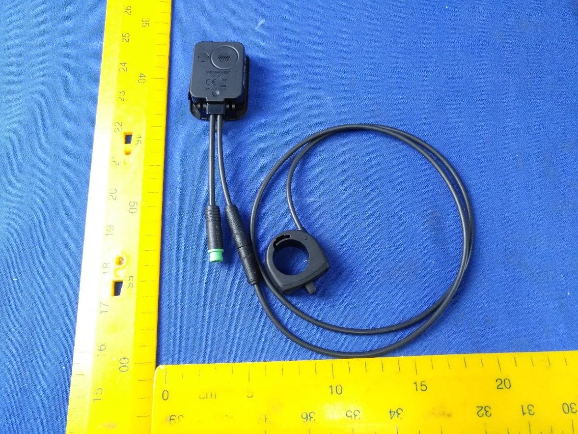
O4GT3
Dec 16, 2023E-Bike HMI with BLE and ANT+
Equipment Class
DTS - Digital Transmission System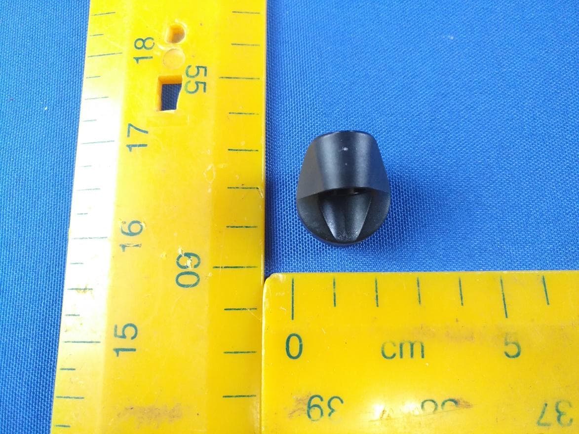
O4GTPMS
Jul 18, 2022SMART BIKE SENSOR with Bluetooth and ANT+ function.
Equipment Class
DTS - Digital Transmission System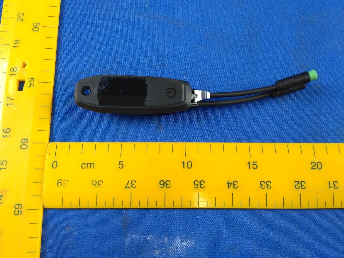
O4GTCU2
Dec 28, 2020E-Bike controller with BLE and ANT+ function
Equipment Class
DXX - Part 15 Low Power Communication Device Transmitter