O4GMULTIW2Multi-Watch
Dayton Industrial Co., Ltd.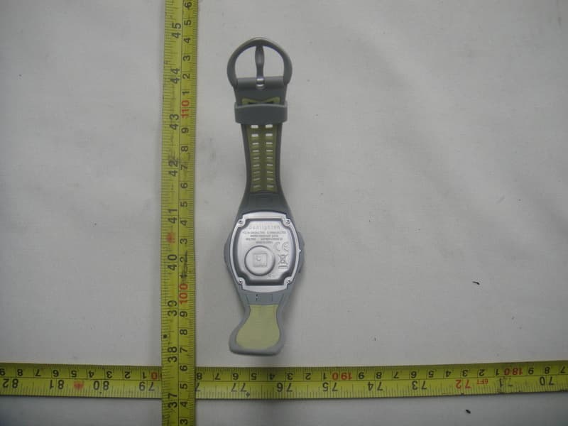
Click to zoom
Application Details
- Equipment Class
- DXT - Part 15 Low Power Transceiver, Rx Verified
- Date of Grant
- Jan 27, 2011
- Application Purpose
- Original Equipment
- Date of Application
- Jan 26, 2011
- Equipment Note
- Multi-Watch
- Frequency Range
- 2450.00000000 - 2457.00000000
- Company
- Dayton Industrial Co., Ltd.
- Country
- Hong Kong
Documents & Files
Document Text
Text extracted from the exhibit documents filed with the FCC. Open a document above to read the original.
Users Manual
1 2 3 4 1 - LAP/MEM Press to set Alarm Press and hold to delete memory in Training mode Press to confirm and advance to the next setting 2 - MODE Press to change modes Press to exit a menu or page 3 - LIGHT/VIEW Press and hold for 5 seconds to turn on/off backlight Press and hold 1 second to turn on/off sound 4 - START/STOP Press to Start or Stop the timer Step 1: Set the Time 1. On the Time screen, press and hold the START/STOP button until the hour setting blinks TIP: Press and hold the MODE or START/STOP buttons to scroll quickly through the hours, minutes, and other Time mode settings. 2. Use the MODE and START/STOP buttons to change each setting Biofeedback Accessories Quick Start User Manual Introduction Thank you for purchasing the Sunlighten Biofeedback Accessories. We are sure you will love these enhancements to your sauna. NOTE: Always consult your physician before you begin or modify any exercise program. Getting Started Buttons 3. Press the LAP/MEM button to advance 4. Continue this process to set month, day, year and 12/24 hour mode Step 2: Set Up Sensors (optional) Press MODE until the setting page appears. Press the LAP/MEM button until “Pair New Device” is displayed. Press START/STOP to initiate pairing, and wait for on-screen confirmation. Step 3: Download Free Software Go to sunlighten.com/biofeedback and follow the on screen instructions. Use this software to store and analyze your biometric data. Step 4: Send Data to Your Computer NOTE: You must download the software as instructed in Step 3 so the necessary USB drivers are installed before connecting the Data Drive to your computer. 1. Plug the Data Drive into an available USB port on your computer Getting Started 2. Bring your Intelli-Watch within range (5m) of your computer 3. Follow the on-screen instructions Using the Heart Rate Monitor The heart rate monitor is on standby and ready to send data. Wear the heart rate monitor directly on your skin, just below your breastplate. It should be snug enough to stay in place during a run. Getting Started Getting Started 1. Unsnap one side of the strap from the heart rate monitor 2. Wet the sensors on the back of the heart rate monitor to create a strong connection between your chest and the transmitter 3. Wrap the strap around your chest and snap in place NOTE: When worn properly, the logo should be right-side up. 4. Bring the Intelli-Watch within range (3m) of the Heart Rate Monitor 5. Press the MODE button to access Sauna mode 6. If you have erratic heart rate data, you may have to tighten the strap or warm up for 5-10 minutes. If the problem persists, you may have to pair the sensors. See page 13. Using the Running Sensor The Running Sensor is on standby and ready to send data (like the Heart Rate Monitor). When you install or move the Running Sensor, the LED blinks three times. 1. Press the tabs on the lace clip. Lift and separate the Running Sensor from the lace clip 2. Loosen your shoe laces slightly 3. Thread the lace clip through 2-3 secure sections of your shoelaces, allowing enough room at the top to tie the shoelaces 4. Tie your shoelaces securely to keep the Running Sensor in place during your workout 5. Snap the Running Sensor into the lace clip and point it toward the front of your shoe Getting StartedTime Mode 6. Bring the Intelli-Watch within range (3m) of the Running Sensor 7. Press the MODE button to access Train mode 8. If the Running Sensor data does not appear, you may have to pair the sensors. See page 13. Press the tabs on the front of the lace clip to remove the Running Sensor. After 30 minutes of inactivity, the Running Sensor automatically turns off to conserve the battery (the LED blinks twice). Time Mode Time mode is the default view of the Intelli-Watch. After 30 minutes of inactivity, the Intelli-Watch automatically returns to the Time screen. Otherwise, press the MODE button until the Time screen appears. Sound On the Time screen, press and hold view to toggle Sound mode. Set the Time See page 4. Set the Alarm 1. On the Time page, press LAP/MEM. The Alarm screen appears 2. Press and hold START/STOP until the hour setting blinks 3. Use MODE and START/STOP to adjust the hour TIP: Press and hold the MODE or START/STOP buttons to scroll quickly through the hours, minutes and other Time mode settings. 4. Use LAP/MEM to advance 5. When finished, press MODE to resume Alarm mode Time Mode Training Mode Training mode displays your current workout settings and data. Press mode until the Training screen appears. Timed Workout 1. Press START/STOP to begin an active session. Press LAP/MEM to mark a known distance during your workout 2. When finished, press START/STOP NOTE: To pause the active session, press START/ STOP. Press again when you are ready to continue the session. Your history includes a rest lap that contains rest time only. 3. To save the workout, press and hold START/STOP Setting NOTE: Settings cannot be modified during an active session in Train mode. 1. Press LAP/MEM to modify user, limits, units or pair a new accessory 2. On User setting, press START/STOP to create your name, then press LAP/MEM to advance NOTE: You can only use START/STOP to set your name. Hold START/STOP to switch letters quickly. 3. On Limits, press START/STOP to adjust limits and press LAP/MEM to advance 4. On the Units screen, press START/STOP to adjust units and use the LAP/MEM button to advance Training Mode Speed 1. Press MODE until you find the Speed screen 2. Press LAP/MEM to adjust settings 3. Press START/STOP to toggle between mi/hr and mi/min 4. Press LAP/MEM to advance 5. Press MODE to finish and exit Result 1. Press MODE until you find the Result screen 2. Press LAP/MEM to toggle through the two sections of results (TRData and WMData) 3. With TRData selected, press START/STOP and heart rate (in bpm) will be displayed 4. Press LAP/MEM to toggle through the results 5. When TRData is shown again, press LAP/MEM to switch to WMData 6. Press START/STOP, then LAP/M…
Text truncated - open the document above for the full version.
External Photos
Neutron Engineering Inc. Project No.: 1010C152 Page 2 of 12 1010C152 1010C152 Neutron Engineering Inc. Project No.: 1010C152 Page 2 of 12 1010C152 1010C152 Neutron Engineering Inc. Project No.: 1010C152 Page 3 of 12 1010C152 1010C152 Neutron Engineering Inc. Project No.: 1010C152 Page 3 of 12 1010C152 1010C152
Internal Photos
Neutron Engineering Inc. Project No.: 1010C152 Page 4 of 12 1010C152 1010C152 Neutron Engineering Inc. Project No.: 1010C152 Page 4 of 12 1010C152 1010C152 Neutron Engineering Inc. Project No.: 1010C152 Page 5 of 12 1010C152 1010C152 Neutron Engineering Inc. Project No.: 1010C152 Page 5 of 12 1010C152 1010C152 Neutron Engineering Inc. Project No.: 1010C152 Page 6 of 12 1010C152 1010C152 Neutron Engineering Inc. Project No.: 1010C152 Page 6 of 12 1010C152 1010C152 Neutron Engineering Inc. Project No.: 1010C152 Page 7 of 12 1010C152 1010C152 Neutron Engineering Inc. Project No.: 1010C152 Page 7 of 12 1010C152 1010C152 Neutron Engineering Inc. Project No.: 1010C152 Page 8 of 12 1010C152 1010C152 Neutron Engineering Inc. Project No.: 1010C152 Page 8 of 12 1010C152 1010C152 Neutron Engineering Inc. Project No.: 1010C152 Page 9 of 12 1010C152 1010C152 Neutron Engineering Inc. Project No.: 1010C152 Page 9 of 12 1010C152 1010C152 Neutron Engineering Inc. Project No.: 1010C152 Page 10 of 12 1010C152 1010C152 Neutron Engineering Inc. Project No.: 1010C152 Page 10 of 12 1010C152 1010C152 Neutron Engineering Inc. Project No.: 1010C152 Page 11 of 12 1010C152 1010C152 Neutron Engineering Inc. Project No.: 1010C152 Page 11 of 12 1010C152 1010C152 Neutron Engineering Inc. Project No.: 1010C152 Page 12 of 12 1010C152 1010C152 Neutron Engineering Inc. Project No.: 1010C152 Page 12 of 12 1010C152 1010C152
Test Report
Neutron Engineering Inc. Report No.: NEI-FICP-1-1010C152 Page 2 of 46 Declaration Neutron represents to the client that testing is done in accordance with standard procedures as applicable and that test instruments used has been calibrated with the standards traceable to National Measurement Laboratory (NML) of R.O.C., or National Institute of Standards and Technology (NIST) of U.S.A. Neutron's reports apply only to the specific samples tested under conditions. It is manufacture’s responsibility to ensure that additional production units of this model are manufactured with the identical electrical and mechanical components. Neutron shall have no liability for any declarations, inferences o r generalizations drawn by the client or others from Neutron issued reports. Neutron’s reports must not be used by the client to claim product endorsement by the authorities or any agency of the Government. This report is the confidential property of the client. As a mutual protection to the clients, the public and Neutron-self, extracts from the test report shall not be reproduced except in full with Neutron’s authorized written approval. Neutron’s laboratory quality assurance procedures are in compliance with the ISO Guide 17025 requirements, and accredited by the conformity assessment authorities listed in this test report. Limitation For the use of the authority's logo is limited unless the Test Standard(s)/Scope(s)/Item(s) mentioned in this test report is (are) included in the conformity assessment authorities acceptance respective. Neutron Engineering Inc. Report No.: NEI-FICP-1-1010C152 Page 3 of 46 Table of Contents Page 1 . CERTIFICATION 5 2 . SUMMARY OF TEST RESULTS 6 2.1 TEST FACILITY 7 2.2 MEASUREMENT UNCERTAINTY 7 3 . GENERAL INFORMATION 8 3.1 GENERAL DESCRIPTION OF EUT 8 3.2 DESCRIPTION OF TEST MODES 10 3.3 BLOCK DIGRAM SHOWING THE CONFIGURATION OF SYSTEM TESTED 11 3.4 DESCRIPTION OF SUPPORT UNITS 12 4 . EMC EMISSION TEST 13 4.1 CONDUCTED EMISSION MEASUREMENT 13 4.1.1 POWER LINE CONDUCTED EMISSION LIMITS 13 4.1.2 MEASUREMENT INSTRUMENTS LIST 13 4.1.3 TEST PROCEDURE 14 4.1.4 DEVIATION FROM TEST STANDARD 14 4.1.5 TEST SETUP 14 4.1.6 EUT OPERATING CONDITIONS 14 4.1.7 TEST RESULTS 15 4.2 RADIATED EMISSION MEASUREMENT 16 4.2.1 RADIATED EMISSION LIMITS 16 4.2.2 MEASUREMENT INSTRUMENTS LIST 17 4.2.3 TEST PROCEDURE 20 4.2.4 DEVIATION FROM TEST STANDARD 20 4.2.5 TEST SETUP 21 4.2.6 EUT OPERATING CONDITIONS 21 4.2.7 TEST RESULTS (BETWEEN 30 – 1000 MHz) 22 4.2.8 TEST RESULTS (ABOVE 1000 MHz) 26 4.2.9 TEST RESULTS (2400 – 2483.5 MHz) 36 5 . BANDWIDTH TEST 37 5.1 MEASUREMENT INSTRUMENTS LIST 37 5.2 TEST PROCEDURE 37 5.3 DEVIATION FROM STANDARD 37 5.4 TEST SETUP 37 5.5 EUT OPERATION CONDITIONS 37 5.6 TEST RESULTS 38 6 . ANTENNA CONDUCTED SPURIOUS EMISSION 40 Neutron Engineering Inc. Report No.: NEI-FICP-1-1010C152 Page 4 of 46 Table of Contents Page 6.1 APPLIED PROCEDURES / LIMIT 40 6.1.1 MEASUREMENT INSTRUMENTS LIST 40 6.1.2 TEST PROCEDURE 40 6.1.3 DEVIATION FROM STANDARD 40 6.1.4 TEST SETUP 40 6.1.5 EUT OPERATION CONDITIONS 40 6.1.6 TEST RESULTS 41 7 . EUT TEST PHOTO 46 Neutron Engineering Inc. Report No.: NEI-FICP-1-1010C152 Page 5 of 46 1. CERTIFICATION Equipment : Multi-watch Brand Name : Sunlighten Model Name. : MULTIW2 A p p l i c a n t : Dayton Industrial Co., Ltd. Date of Test : Dec. 05, 2010 ~ Dec. 08, 2010 T e s t I t e m : ENGINEERING SAMPLE Standards : FCC Part15, Subpart C(15.249)/ ANSI C63.4 : 2003; Canada RSS-210:2010 The above equipment has been tested and found compliance with the requirement of the relative standards by Neutron Engineering Inc. EMC Laboratory. The test data, data evaluation, and equipment configuration contained in our test report (Ref No. NEI-FICP-1-1010C152) were obtained utilizing the test procedures, test instruments, test sites that has been accredited by the Authority of NVLAP and TAF according to the ISO-17025 quality assessment standard and technical standard(s). Neutron Engineering Inc. Report No.: NEI-FICP-1-1010C152 Page 6 of 46 2. SUMMARY OF TEST RESULTS Test procedures according to the technical standards: FCC Part15, Subpart C (15.249) Canada RSS-210:2010 Canada FCC Test Item Judgment Remark 15.207 Conducted Emission - N/A A2.9(a) 15.209 Radiated emission PASS A2.9(a) 15.249 Radiated Spurious EmissionPASS NOTE: (1)” N/A” denotes test is not applicable in this Test Report Neutron Engineering Inc. Report No.: NEI-FICP-1-1010C152 Page 7 of 46 2.1 TEST FACILITY The test facilities used to collect the test data in this report is DG-C02/DG-CB03at the location of No.3,Jinshagang 1st Road, ShiXia, Dalang Town,Dong Guan, China.523792 Neutron's test firm number for FCC 319330 Neutron's test firm number is 4428B-1 2.2 MEASUREMENT UNCERTAINTY Where relevant, the following measurement uncertainty levels have been estimated for tests performed on the EUT as specified in CISPR 16-4-2: The reported uncertainty of measurement y ± U,where expended uncertainty U is based on a standard uncertainty multiplied by a coverage factor of k=2,providing a level of confidence of approximately 95 %。 A. Conducted Measurement : Test Site Method Measurement Frequency Range U,(dB) NOTE DG-C02 CISPR 150 KHz ~ 30MHz 1.94 B. Radiated Measurement : Test Site Method Measurement Frequency Range Ant. H / V U,(dB) NOTE 30MHz ~ 200MHz V 2.48 30MHz ~ 200MHz H 2.16 200MHz ~ 1,000MHz V 2.50 DG-CB03 CISPR 200MHz ~ 1,000MHz H 2.66 Neutron Engineering Inc. Report No.: NEI-FICP-1-1010C152 Page 8 of 46 3. GENERAL INFORMATION 3.1 GENERAL DESCRIPTION OF EUT Equipment Multi-watch Brand Name Sunlighten Model Name. MULTIW2 OEM Brand/Model Name N/A Model Difference N/A Product Description The EUT is a Multi-watch . Product Type Low Power Communication Device Operation Frequency: 2450 MHz / 2457 MHz Modulation Type: GFSK Date rate: 1Mbps Number Of Channel 2CH .Please see note 2. Antenna Designation: Integral antenna Antenna Gain(Peak) 0 dBi Output Power: 42.34dBuV/m (AV Max.) More details of EUT technical spec…
Text truncated - open the document above for the full version.
Test Setup Photos
Neutron Engineering Inc. Report No.: NEI-FICP-1-1010C152 Page 46 of 46 7. EUT TEST PHOTO Radiated Measurement Photos Neutron Engineering Inc. Report No.: NEI-FICP-1-1010C152 Page 46 of 46 7. EUT TEST PHOTO Radiated Measurement Photos
Contact Information
Applicant
Wong Lap Fai(Project Manager)
Technical Contact
Neutron Engineering Inc.Cathy Wang
[email protected]+886-769-83183000
No.3,Jinshagang 1st Rd, ShiXia,Dalang Town · Dongguan · China
Non-Technical Contact
Neutron Engineering Inc.Cathy Wang
[email protected]+886-769-83183000
Test Firm
BTL Inc.Daisy Dai
Technical Specifications
| # | Rule Parts | Frequency Range | Power Output |
|---|---|---|---|
| 1 | 15C | 2.45 GHz - 2.46 GHz | - |
Other Applications from Dayton Industrial Co., Ltd.
O4G387
May 19, 2026RS HMI Control
Equipment Class
DTS - Digital Transmission System
O4GHRM25
Feb 10, 2026LINK2CARE
Equipment Class
DTS - Digital Transmission System
O4GT3
Dec 16, 2023E-Bike HMI with BLE and ANT+
Equipment Class
DTS - Digital Transmission System
O4GTPMS
Jul 18, 2022SMART BIKE SENSOR with Bluetooth and ANT+ function.
Equipment Class
DTS - Digital Transmission System
O4GTCU2
Dec 28, 2020E-Bike controller with BLE and ANT+ function
Equipment Class
DXX - Part 15 Low Power Communication Device Transmitter