O4GNODEBicycle Computer
Dayton Industrial Co., Ltd.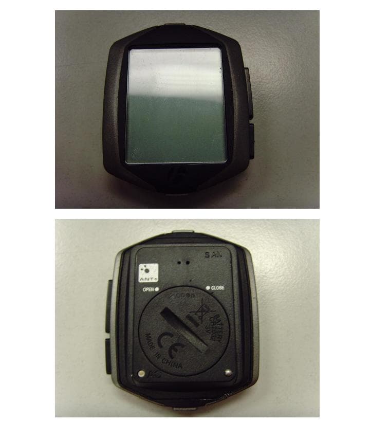
Click to zoom
Application Details
- Equipment Class
- DXX - Part 15 Low Power Communication Device Transmitter
- Date of Grant
- Nov 26, 2013
- Application Purpose
- Original Equipment
- Date of Application
- Nov 26, 2013
- Equipment Note
- Bicycle Computer
- Frequency Range
- 2457.00000000 - 2457.00000000
- Company
- Dayton Industrial Co., Ltd.
- Country
- Hong Kong
Documents & Files
Document Text
Text extracted from the exhibit documents filed with the FCC. Open a document above to read the original.
Users Manual
EN NODE 1.1 & NODE 2.1 Quick Start Guide About this manual Please read this manual carefully. If you do not understand the information, or you have a question that this manual does not cover, consult your Bontrager dealer or download the complete instruction manual from www.bontrager.com/support/owners_manuals. BT11_EN_ES_FR_DE_JA_NODE_QSG_update.indd 112/21/11 9:31 AM 2 A BDEG F C I H J A Handlebar clamp B Rubber pad C Brackets D Battery E Rubber shim F Zip ties G Screw & washer H Battery cover I Rubber o-ring J Heart rate strap (NODE 2.1 only) Safety When riding your bicycle, do not stare at the computer for a long time. If you do not watch the road, you could hit an obstacle, which might cause you to lose control and fall. Parts List Tools required + Screwdriver, Phillips type + Coin BT11_EN_ES_FR_DE_JA_NODE_QSG_update.indd 212/21/11 9:31 AM 3 EN Installation Step 1: Install the Speed Sensor Your NODE is not packed with a speed sensor. See your sensor packaging for sensor installation instructions. Step 2: Attach the computer base Attach to a handlebar + Insert the correct handlebar clamp (A) into the computer base (C) (Figure 1). + Slide the head of the handlebar clamp to the end of the slot in the computer base. + Insert the rubber pad (B) with logo into the back of the computer base (Figure 2). + With the screw hole toward the back of the bike, wrap the handlebar clamp around the handlebar. + Insert the screw and washer (G) and tighten with the screwdriver until the computer base no longer rotates on the handlebar (Figure 3). Do not overtighten. Figure 1. Handlebar clamp in back of computer base. Figure 2. Pad inserted in computer base. Figure 3. Tighten screw. BT11_EN_ES_FR_DE_JA_NODE_QSG_update.indd 312/21/11 9:31 AM 4 Figure 4. Pad inserted in computer base. Figure 5. Base on stem. Attach to a stem + Insert the rubber pad (B) with logo into the back of the computer base (C) (Figure 4). + Position the computer base on the stem with the screw hole toward the back of the bike (Figure 5). + Secure the computer base to the stem using zip-ties (F). BT11_EN_ES_FR_DE_JA_NODE_QSG_update.indd 412/21/11 9:31 AM 5 EN Step 3: Install the battery + Insert the supplied battery (D) with the ‘+’ facing up or out (Figure 6). + Press the rubber o-ring (I) into the groove around the battery in the computer. (Figure 7) + Place the battery cover (H) over the battery with the slot facing upward. + Turn the cover clockwise with a coin. (Figure 8) + Slide the computer into the computer base (Figure 9) being careful not to press any buttons. Figure 8. Turn cover clockwise with coin. Figure 7. Insert rubber o-ring into groove.Figure 6. Battery Orientation During Installation. Figure 9. Slide computer into computer base. BT11_EN_ES_FR_DE_JA_NODE_QSG_update.indd 512/21/11 9:31 AM 6 Step 4: Program the computer 4:1. Wake the computer: Images and words appear on the screen, proceed to step 4.2 If the screen is blank, push any button on the computer 4:2. Select the language: To change the language (choose English, Francais, Espanol, Deutsch), press T or B To save the language and proceed to the next function, press s1 4:3. Select clock: To change the type of clock (choose 12HR or 24HR), press s2 To save the clock and proceed to the next function, press s1 4:4. Set hours: To change the hours, press T or B To set the hours and proceed to minutes, press s2 BT11_EN_ES_FR_DE_JA_NODE_QSG_update.indd 612/21/11 9:31 AM 7 4:1. 4:3. 4:4. 4:2. s1 s1 s1 s2 s2 s2 B B B T T T EN or or BT11_EN_ES_FR_DE_JA_NODE_QSG_update.indd 712/21/11 9:31 AM 8 4:5. Set the minutes: To change the minutes, press T or B If desired, you can go back to the hours in the previous step by pressing s2 To save the SET CLOCK (time) and proceed to the next function, press s1 4:6. Set the wheel size: To change the wheel size (choose from the wheel size menu), press T or B To set a custom wheel size, see the Complete NODE Manual at Bontrager.com To save the wheel and proceed to the next function, press s1 Wheel size menu 700 x 20 700 x 23 700 x 25 700 x 28 700 x 32 700 x 35 700 x 38 26 x 1.5 26 x 1.9 26 x 2.0 26 x 2.1 26 x 2.2 Custom 4:7. Set units: To change units (choose KM or MILES), press s2 To save the Units and proceed to the Odometer function, press s1 BT11_EN_ES_FR_DE_JA_NODE_QSG_update.indd 812/21/11 9:31 AM 9 4:5. 4:6. 4:7. s1 s1 s1 s2 B B T T EN or or BT11_EN_ES_FR_DE_JA_NODE_QSG_update.indd 912/21/11 9:31 AM 10 4:8. Set odometer: To skip this step and leave the value at 00000, press s1 and go to step 4:10 To change the highlighted number, press T or B To select a value and proceed to the next digit, press s2 4:9. Repeat for each of the other four digits: To change the highlighted number, press T or B To select a value and proceed to the next digit, press s2 If desired, you can go back to the first digit (and then the other digits) by pressing s2 To save the odometer and proceed to the next process, press s1 4:10. Activate sensors: Speed: spin the wheel Cadence: rotate the crank arm Heart rate: wear the chest strap Power: rotate the crank arm (or, for a hub sensor, turn the wheel) 4:11. Wait for pairing to complete: Note: the Node computer must be within 5 feet (1.5 meters) of the installed sensor(s). 4:12. Finish programming: When the screen shows “Setup Complete,” press s1 to save all your settings and switch to the Ride mode. BT11_EN_ES_FR_DE_JA_NODE_QSG_update.indd 1012/21/11 9:31 AM 11 4:8. 4:9. 4:11.4:12. s1 s1 s2 s2 B B T T EN or or BT11_EN_ES_FR_DE_JA_NODE_QSG_update.indd 1112/21/11 9:31 AM 12 Force pair If the NODE fails to pair with a sensor, you can force the pairing process: In RIDE mode, hold s1 and s2 for three seconds (Figure 11) and activate sensors. Step 5: Enjoy your ride Starting a ride from sleep mode Step 1: Connect sensors Activate sensors During the connecting process, the display shows CONNECTING SENSORS and the lower right corner of the display flashes the ‘receiving’ icon (Figure 12). BT11_EN_ES_FR_DE_JA_NODE_QSG_upd…
Text truncated - open the document above for the full version.
Cover Letter(s)
Dayton Industrial Co., Ltd. Nov. 08, 2013 Federal Communications Commission Authorization and Evaluation Division FCC ID:O4GNODE Confidentiality Request Pursuant to Sections 0.457 and 0.459 of the Commission’s Rules, the applicant hereby requests confidential treatment of information applied this application as outlined below: 1. Block Diagram 2. Circuit Diagram 3. Operational Description 4. Part List The above materials contain trade secrets and proprietary information not customarily released to the public. The public disclosure of these matters might be harmful to the applicant and provide unjustified benefits to its competitors. The Applicant understands that pursuant to Rule 0.457, disclosure of this Application and all accompanying documentation will not be made before the date of the Grant for this application Sincerely, Signature Name/Title: Wong Lap Fai/ Manager Applicant: Dayton Industrial Co., Ltd ADDRESS: 2-12 Kwai Fat Road, 11-A Kwai Chung, New Territories, Hong Kong TEL: 852 24224404 FAX: 852 24804627 Email: [email protected]
External Photos
External Photos Node 1.1 Node 2.1
Internal Photos
Internal Photos Node1.1 Node 2.1
Test Report
Report Number: 60/790.13.021.01 Page 1 of 17 TÜV SÜD HONG KONG LTD., 3/F, West Wing, Lakeside 2, 10 Science Park West Avenue, Science Park, Shatin, HK. Tel: +852-2776 1323 Fax: +852-2776 1206 Rev. no.: 2.1 TÜV SÜD HONG KONG LTD., Unit 601, InnoCentre, 72 Tat Chee Avenue, Kowloon Tong, Hong Kong. Tel: +852-2776 1323 Fax: +852-2776 1206 FCC / IC – Test report Report Number : 60/790.13.021.01 Date of Issue: 07 th Aug 2013 Model : Node 1.1,Node 2.1 Product Type : Bicycle Computer Applicant : Dayton Industrial Co., Ltd. Address : 2-12 Kwai Fat Road, 11-A Kwai Chung, New Territories, Hong Kong Production Facility : Kendy Enterprise Ltd. Address : 2-12 Kwai Fat Road, 11-A Kwai Chung, New Territories, Hong Kong Test Result : Positive Negative Total pages including Appendices : 17 TÜV SÜD Hong Kong Ltd. is a subcontractor to TÜV Product Service, GmbH according to the principles outlined in ISO 17025. TÜV SÜD Hong Kong Ltd. reports apply only to the specific samples tested under stated test conditions. Construction of the actual test samples has been documented. It is the manufacturer's responsibility to assure that additional production units of this model are manufactured with identical electrical and mechanical components. The manufacturer/importer is responsible to the Competent Authorities in Europe for any modifications made to the production units which result in non-compliance to the relevant regulations. TÜV SÜD Hong Kong Ltd. shall have no liability for any deductions, inferences or generalizations drawn by the client or others from TÜV SÜD Hong Kong Ltd. issued reports. This report is the confidential property of the client. As a mutual protection to our clients, the public and ourselves, extracts from the test report shall not be reproduced except in full without our written approval. Report Number: 60/790.13.021.01 Page 2 of 17 TÜV SÜD HONG KONG LTD., 3/F, West Wing, Lakeside 2, 10 Science Park West Avenue, Science Park, Shatin, HK. Tel: +852-2776 1323 Fax: +852-2776 1206 Rev. no.: 2.1 TÜV SÜD HONG KONG LTD., Unit 601, InnoCentre, 72 Tat Chee Avenue, Kowloon Tong, Hong Kong. Tel: +852-2776 1323 Fax: +852-2776 1206 1. Table of Contents 1. Table of Contents ..................................................................................................................... 2 2. Details about the Test Laboratory ............................................................................................ 3 3. Description of the Equipment Under Test ................................................................................. 4 4. Summary of Test Standards ..................................................................................................... 5 5. Summary of Test Standards and Results ................................................................................. 6 6. General Remarks ..................................................................................................................... 7 7. Emission Test Results .............................................................................................................. 8 7.1 Radiated Emission Test ..................................................................................................... 8 7.2 20dB bandwidth measurement ........................................................................................ 12 7.3 Bandedge measurement ................................................................................................. 14 8. System Measurement Uncertainty ......................................................................................... 17 Report Number: 60/790.13.021.01 Page 3 of 17 TÜV SÜD HONG KONG LTD., 3/F, West Wing, Lakeside 2, 10 Science Park West Avenue, Science Park, Shatin, HK. Tel: +852-2776 1323 Fax: +852-2776 1206 Rev. no.: 2.1 TÜV SÜD HONG KONG LTD., Unit 601, InnoCentre, 72 Tat Chee Avenue, Kowloon Tong, Hong Kong. Tel: +852-2776 1323 Fax: +852-2776 1206 2. Details about the Test Laboratory Details about the Test Laboratory Test site 1 Company name: TÜV SÜD HONG KONG LTD. 3/F, West Wing, Lakeside 2, 10 Science Park West Avenue, Science Park, Shatin HK. Telephone: 852 2776 1323 Fax: 852 2776 1372 Test site 2 Company name: TMC-Telecommunication Metrology Center of M.I.I.T No 52 Hua Yuanbei Road, Haidian District, Beijing, P.R.China Report Number: 60/790.13.021.01 Page 4 of 17 TÜV SÜD HONG KONG LTD., 3/F, West Wing, Lakeside 2, 10 Science Park West Avenue, Science Park, Shatin, HK. Tel: +852-2776 1323 Fax: +852-2776 1206 Rev. no.: 2.1 TÜV SÜD HONG KONG LTD., Unit 601, InnoCentre, 72 Tat Chee Avenue, Kowloon Tong, Hong Kong. Tel: +852-2776 1323 Fax: +852-2776 1206 3. Description of the Equipment Under Test Description of the Equipment Under Test Product: Bicycle Computer Model no.: Node 1.1, Node 2.1 Serial number: NIL Options and accessories: NIL Rated Voltage: 3.0 VDC Rated Current: NIL Rated Power: NIL Frequency: NIL RF Transmission Frequency: 2457MHz Antenna gain: 0 dBi No. of Operated Channel: 1 Modulation: GFSK Description of the EUT: Battery operated – 1 x3.0V CR2032 battery Report Number: 60/790.13.021.01 Page 5 of 17 TÜV SÜD HONG KONG LTD., 3/F, West Wing, Lakeside 2, 10 Science Park West Avenue, Science Park, Shatin, HK. Tel: +852-2776 1323 Fax: +852-2776 1206 Rev. no.: 2.1 TÜV SÜD HONG KONG LTD., Unit 601, InnoCentre, 72 Tat Chee Avenue, Kowloon Tong, Hong Kong. Tel: +852-2776 1323 Fax: +852-2776 1206 4. Summary of Test Standards Test Standards FCC Part 15 Subpart C, Intentional Radiators, 10-1-12 Edition PART 15 – RADIO FREQUENCY DEVICES Subpart C – Intentional Radiators RSS-Gen Issue 3 December 2010 General Requirements and Information for the Certification of Radio Apparatus RSS-210 Issue 8 December 2010 RSS-210 — Licence-exempt Radio Apparatus (All Frequency Bands): Category I Equipment Report Number: 60/790.13.021.01 Page 6 of 17 TÜV SÜD HONG KONG LTD., 3/F, West Wing, Lakeside 2, 10 Science Park West Avenue, Science Park, Shatin, HK. Tel: +852…
Text truncated - open the document above for the full version.
Test Setup Photos
Node 2.1
Contact Information
Applicant
Wong Lap Fai(Project Manager)
Test Firm
TMC-Telecommunication Metrology Center of M.I.I.TBojun Zhang
[email protected]00861062304633
Technical Specifications
| # | Rule Parts | Frequency Range | Power Output |
|---|---|---|---|
| 1 | 15C | 2.46 GHz - 2.46 GHz | - |
Other Applications from Dayton Industrial Co., Ltd.
O4G387
May 19, 2026RS HMI Control
Equipment Class
DTS - Digital Transmission System
O4GHRM25
Feb 10, 2026LINK2CARE
Equipment Class
DTS - Digital Transmission System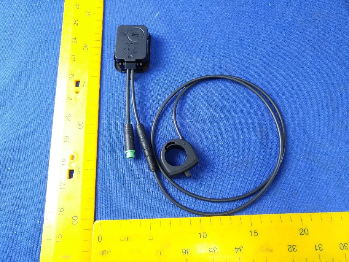
O4GT3
Dec 16, 2023E-Bike HMI with BLE and ANT+
Equipment Class
DTS - Digital Transmission System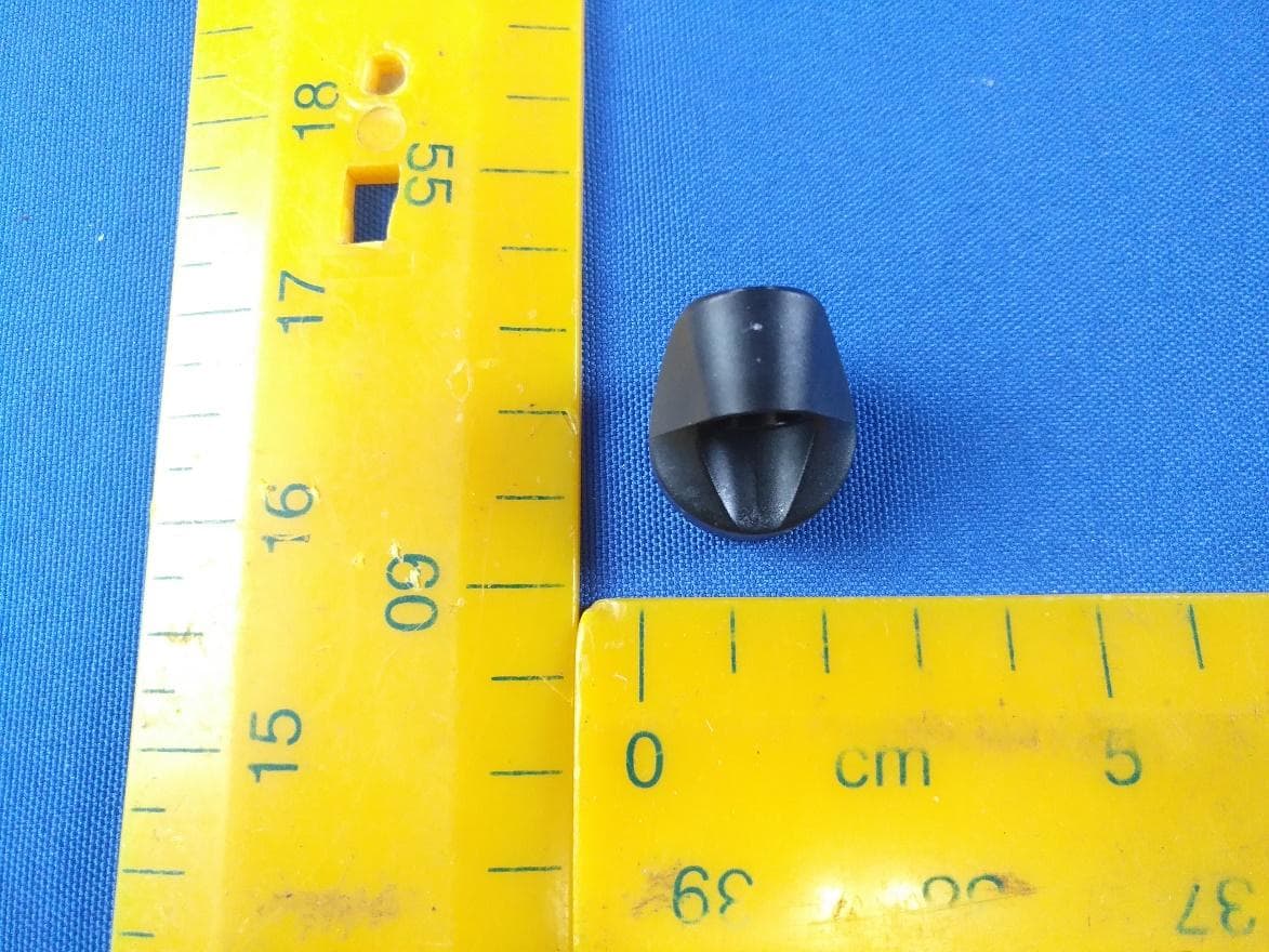
O4GTPMS
Jul 18, 2022SMART BIKE SENSOR with Bluetooth and ANT+ function.
Equipment Class
DTS - Digital Transmission System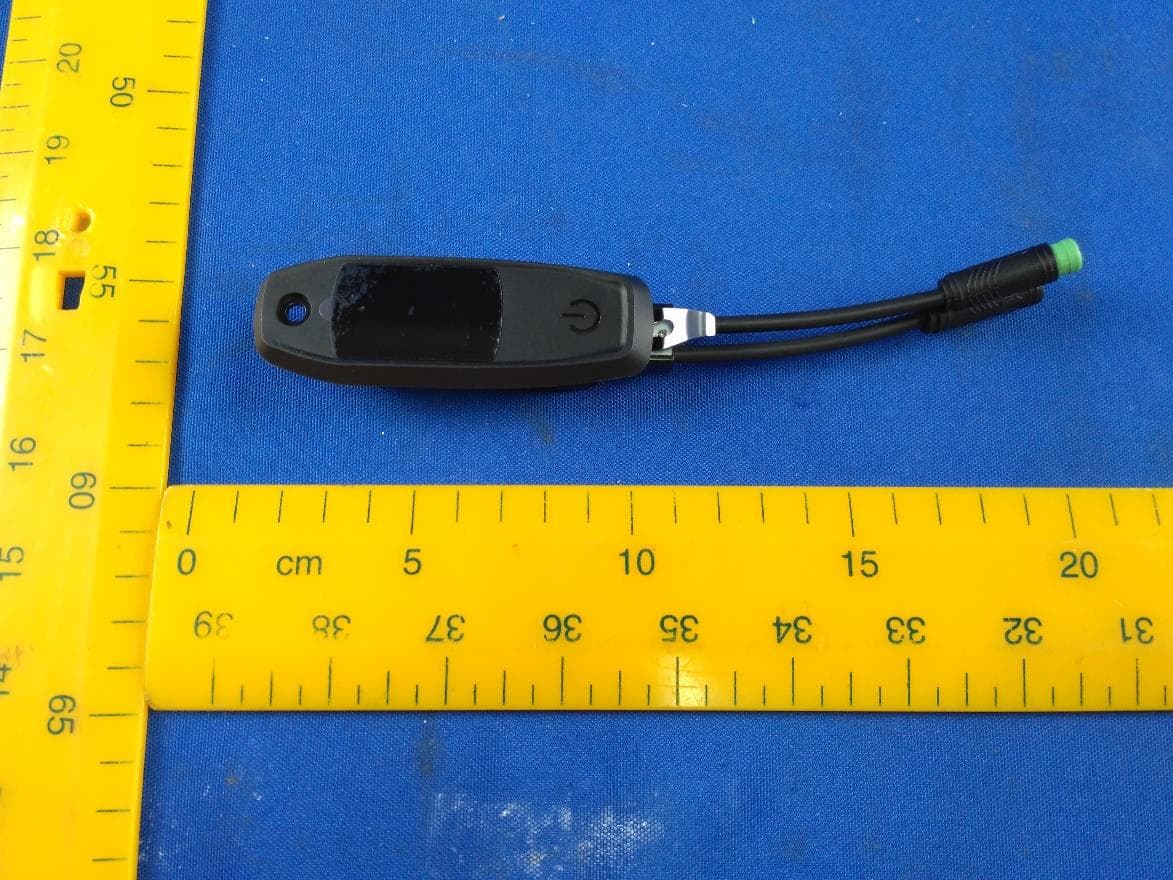
O4GTCU2
Dec 28, 2020E-Bike controller with BLE and ANT+ function
Equipment Class
DXX - Part 15 Low Power Communication Device Transmitter