O4GREMOTEMultiremote
Dayton Industrial Co., Ltd.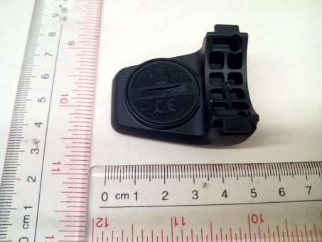
Click to zoom
Application Details
- Equipment Class
- DTS - Digital Transmission System
- Date of Grant
- May 12, 2014
- Application Purpose
- Original Equipment
- Date of Application
- May 12, 2014
- Equipment Note
- Multiremote
- Frequency Range
- 2402.00000000 - 2480.00000000
- Company
- Dayton Industrial Co., Ltd.
- Country
- Hong Kong
Documents & Files
Document Text
Text extracted from the exhibit documents filed with the FCC. Open a document above to read the original.
Users Manual
AC B Bar adapter Status LED D 1x multiremote 1x 2x 1x Content / Inhalt / Contenu / Inhoud / ContenidoInstallation / Montage / Fitting / Bevestiging / Instalación The multiremote has three buttons, which are marked with the symbols (▲, ● and ▼ ). Additionally there is a red/green LED located at the center. To mount the remote control a handlebar adapter and various rubber rings are provided. 1 multiremote parts To activate the remote control press the center button. Once the remote is activated, the status LED is flashing periodically. Assembly on the left side of the handlebar After you have installed the multiremote on the left side, please press and hold the upper and middle buttons (▲ and ●) for about 2 seconds. Once the Status LED turns green for 2 seconds, the remote control is set to the left side of the handlebar. Assembly on the right side of the handlebar After you have installed the multiremote on the right side, please press and hold the upper and middle buttons (▲ and ●) for about 2 seconds. Once the Status LED turns red for 2 seconds, the remote control is set to the right side of the handlebar. The multiremote will switch automatically to standby mode after up to 150 seconds, when the head unit is no longer activated. If the Status LED flashs during operation periodically red, the batte- ry is almost completely drained and should be replaced. The battery of the multiremote can be changed without special knowledge and by using a 50 Euro cent coin. For this purpose, a standard CR2032 battery is required, which is inserted into the new remote control. LED flashing green: multiremote is ready to use and connected to the head unit. Flashing green and red together: multiremote is ready to use but searches for the „paired“ head unit. a) Please bring the head unit within the transmission range (1m). b) Devices are not paired. Please see chapter „pairing“. LED flashing red: Battery weak Please replace the battery. No flashing even though botton press: Battery completely discharged Please replace the battery. Electromagnetic Interferences: Disturbance may occure near electrical devices such as LED lights, motors or electrical brakes. Also WLAN access points may cause interference when using multiremote. To avoid problems move away from possible sources of disturbance. Please refer also to the User’s Guide of your head unit (App or ANT+ ™ device) to ensure that the pairing mode is activated if needed. To find compatible apps please refer to our homepage. 1. Bring the multiremote in the near (1m) of the head unit. 2. Please press and hold the upper and lower button (▲ and ▼) for about 2 seconds until the Status LED lights flashs green and red together for 2 seconds. 3. Now the multiremote is looking for a head unit (Status LED flashes green and red together). 4. If required, follow the specific instructions for „pairing“ in the User‘s Guide of your head unit. 5. Once the Status LED is flashing green, the multiremote is connected to the head unit successfully. 3 Turning the multiremote on 4 Adjusting the assembly side of the bar 5 Pairing 6 Turn your multiremote off 7 Replacing the battery 8 Overview of Status LEDs We are only liable for damages in accordance to the statutory regulations in respect to our contractual partners. Batteries are excluded from warranties. In case of a warranty please contact the retailer where you purchased your device. Batteries may not be disposed of with the regular household. 10 Warranty The multiremote can be mounted on the left or on the right side of a handlebar. To achieve correct key assignment, please refer to „Adjusting the assembly side“ of this manual once the multiremote has been mounted. 2 Mounting of multiremote Dimensions: 48 x 38 x 21 mm (L x W x H) Weight: ca. 15g (incl. CR2032 battery) Water resistance: 1m Compatibility: ANT+, Bluetooth® 4.0 Radio frequency: 2,4 GHz ANT™, Bluetooth® 4.0 Transmission range: 3m Operating temperature: -10°C – 60°C Battery: CR2032 Lithium Battery. Battery lifetime: up to 100 hours operating 9 Technical specifications 11 FCC STATMENT This device complies with Part 15 of the FCC Rules. Operation is subject to the following two conditions: (1) This device may not cause harmful interference, and (2) This device must accept any interference received, including interference that may cause undesired operation. NOTE The grantee is not responsible for any changes or modifications not expressly approved by the party responsible for compliance. Such modifications could void the user’s authority to operate the equipment. This equipment has been tested and found to comply with the limits for a Class B digital device, pursuant to part 15 of the FCC Rules. These limits are designed to provide reasonable protection against harmful interference in a residential installation. This equipment generates, uses and can radiate radio frequency energy and, if not installed and used in accordance with the instructions, may cause harmful interference to radio communications. However, there is no guarantee that interference will not occur in a particular installation. If this equipment does cause harmful interference to radio or television reception, which can be determined by turning the equipment off and on, the user is encouraged to try to correct the interference by one or more of the following measures: —Reorient or relocate the receiving antenna. —Increase the separation between the equipment and receiver. —Connect the equipment into an outlet on a circuit different from that to which the receiver is connected. —Consult the dealer or an experienced radio/TV technician for help.
Cover Letter(s)
Dayton Industrial Co., Ltd. May 07, 2014 Federal Communications Commission Authorization and Evaluation Division FCC ID:O4GREMOTE Confidentiality Request Pursuant to Sections 0.457 and 0.459 of the Commission’s Rules, the applicant hereby requests confidential treatment of information applied this application as outlined below: 1. Block Diagram 2. Circuit Diagram 3. Operational Description The above materials contain trade secrets and proprietary information not customarily released to the public. The public disclosure of these matters might be harmful to the applicant and provide unjustified benefits to its competitors. The Applicant understands that pursuant to Rule 0.457, disclosure of this Application and all accompanying documentation will not be made before the date of the Grant for this application Sincerely, Signature Name/Title: Wong Lap Fai/ Manager Applicant: Dayton Industrial Co., Ltd ADDRESS: 2-12 Kwai Fat Road, 11-A Kwai Chung, New Territories, Hong Kong TEL: 852 24224404 FAX: 852 24804627 Email: [email protected]
External Photos
External Photos (Duotrap S)
Internal Photos
Internal Photos (Duotrap S) 2.4G Antenna antenna
Test Report
Report Number: 60/790.14.006.01 Page 1 of 28 TÜV SÜD HONG KONG LTD., 3/F, West Wing, Lakeside 2, 10 Science Park West Avenue, Science Park, Shatin, HK. Tel: +852-2776 1323 Fax: +852-2776 1206 Rev. no.: 2.1 FCC – Test report Report Number : 60/790.14.006.01 Date of Issue: 29 th April 2014 Model : REMOTE Product Type : Multiremote Applicant : Dayton Industrial Co., Ltd Address : 2-12 Kwai Fat Road, 11-A Kwai Chung, New Territories, HK Production Facility : Dayton Industrial Co., Ltd Address : 2-12 Kwai Fat Road, 11-A Kwai Chung, New Territories, HK Test Result : Positive Negative Total pages including Appendices : 28 TÜV SÜD Hong Kong Ltd. is a subcontractor to TÜV Product Service, GmbH according to the principles outlined in ISO 17025. TÜV SÜD Hong Kong Ltd. reports apply only to the specific samples tested under stated test conditions. Construction of the actual test samples has been documented. It is the manufacturer's responsibility to assure that additional production units of this model are manufactured with identical electrical and mechanical components. The manufacturer/importer is responsible to the Competent Authorities in Europe for any modifications made to the production units which result in non-compliance to the relevant regulations. TÜV SÜD Hong Kong Ltd. shall have no liability for any deductions, inferences or generalizations drawn by the client or others from TÜV SÜD Hong Kong Ltd. issued reports. This report is the confidential property of the client. As a mutual protection to our clients, the public and ourselves, extracts from the test report shall not be reproduced except in full without our written approval. Report Number: 60/790.14.006.01 Page 2 of 28 TÜV SÜD HONG KONG LTD., 3/F, West Wing, Lakeside 2, 10 Science Park West Avenue, Science Park, Shatin, HK. Tel: +852-2776 1323 Fax: +852-2776 1206 Rev. no.: 2.1 1. Table of Contents 1. Table of Contents ................................................................................................................................................................. 2 2. Details about the Test Laboratory .................................................................................................................................... 3 3. Description of the Equipment Under Test ..................................................................................................................... 4 4. Summary of Test Standards .............................................................................................................................................. 5 5. Summary of Test Standards and Results ...................................................................................................................... 6 6. General Remarks .................................................................................................................................................................. 7 7. Emission Test Results ........................................................................................................................................................ 8 7.1 Spurious Emissions at Antenna Terminals ........................................................................................................... 8 7.2 Spurious Radiated Emissions ................................................................................................................................ 11 7.3 6dB Bandwidth ........................................................................................................................................................... 15 7.4 Peak Output Power Measurements ....................................................................................................................... 18 7.5 100 kHz Bandwidth of Band Edges ...................................................................................................................... 21 7.6 Power Spectral Density ............................................................................................................................................ 23 7.7 Antenna Requirement ............................................................................................................................................... 26 8. Test Equipment List ........................................................................................................................................................... 27 9. System Measurement Uncertainty ................................................................................................................................. 28 Report Number: 60/790.14.006.01 Page 3 of 28 TÜV SÜD HONG KONG LTD., 3/F, West Wing, Lakeside 2, 10 Science Park West Avenue, Science Park, Shatin, HK. Tel: +852-2776 1323 Fax: +852-2776 1206 Rev. no.: 2.1 2. Details about the Test Laboratory Details about the Test Laboratory Test site 1 Company name: TÜV SÜD HONG KONG LTD. 3/F, West Wing, Lakeside 2, 10 Science Park West Avenue, Science Park, Shatin HK. Telephone: 852 2776 1323 Fax: 852 2776 1372 Test site 2 Company name: TMC-Telecommunication Metrology Center of M.I.I.T No 52 Hua Yuanbei Road, Haidian District, Beijing, P.R.China Report Number: 60/790.14.006.01 Page 4 of 28 TÜV SÜD HONG KONG LTD., 3/F, West Wing, Lakeside 2, 10 Science Park West Avenue, Science Park, Shatin, HK. Tel: +852-2776 1323 Fax: +852-2776 1206 Rev. no.: 2.1 3. Description of the Equipment Under Test Description of the Equipment Under Test Product: Multiremote Model no.: REMOTE Serial number: NIL Options and accessories: NIL FCC ID: 04GREMOTE Rated Voltage: 3 VDC Rated Current: NIL Rated Power: NIL Frequency: 2402-2480MHz RF Transmission Frequency: 2402-2480MHz Antenna gain: 0 dBi No. of Operated Channel: 40 Modulation: GFSK Description of the EUT: Battery operated – 1x 3V battery Report Number: 60/790.14.006.01 Page 5 of 28 TÜV SÜD HONG KONG LTD., 3/F, West Wing, Lakeside 2, 10 Science Park West Avenue, Science Park, Shatin, HK. Tel: +852-2…
Text truncated - open the document above for the full version.
Contact Information
Applicant
Wong Lap Fai(Project Manager)
Test Firm
Eurofins E&E Wireless Taiwan Co., LtdFly LU
Technical Specifications
| # | Rule Parts | Frequency Range | Power Output |
|---|---|---|---|
| 1 | 15C | 2.40 GHz - 2.48 GHz | 1.50 mW |
Other Applications from Dayton Industrial Co., Ltd.
O4G387
May 19, 2026RS HMI Control
Equipment Class
DTS - Digital Transmission System
O4GHRM25
Feb 10, 2026LINK2CARE
Equipment Class
DTS - Digital Transmission System
O4GT3
Dec 16, 2023E-Bike HMI with BLE and ANT+
Equipment Class
DTS - Digital Transmission System
O4GTPMS
Jul 18, 2022SMART BIKE SENSOR with Bluetooth and ANT+ function.
Equipment Class
DTS - Digital Transmission System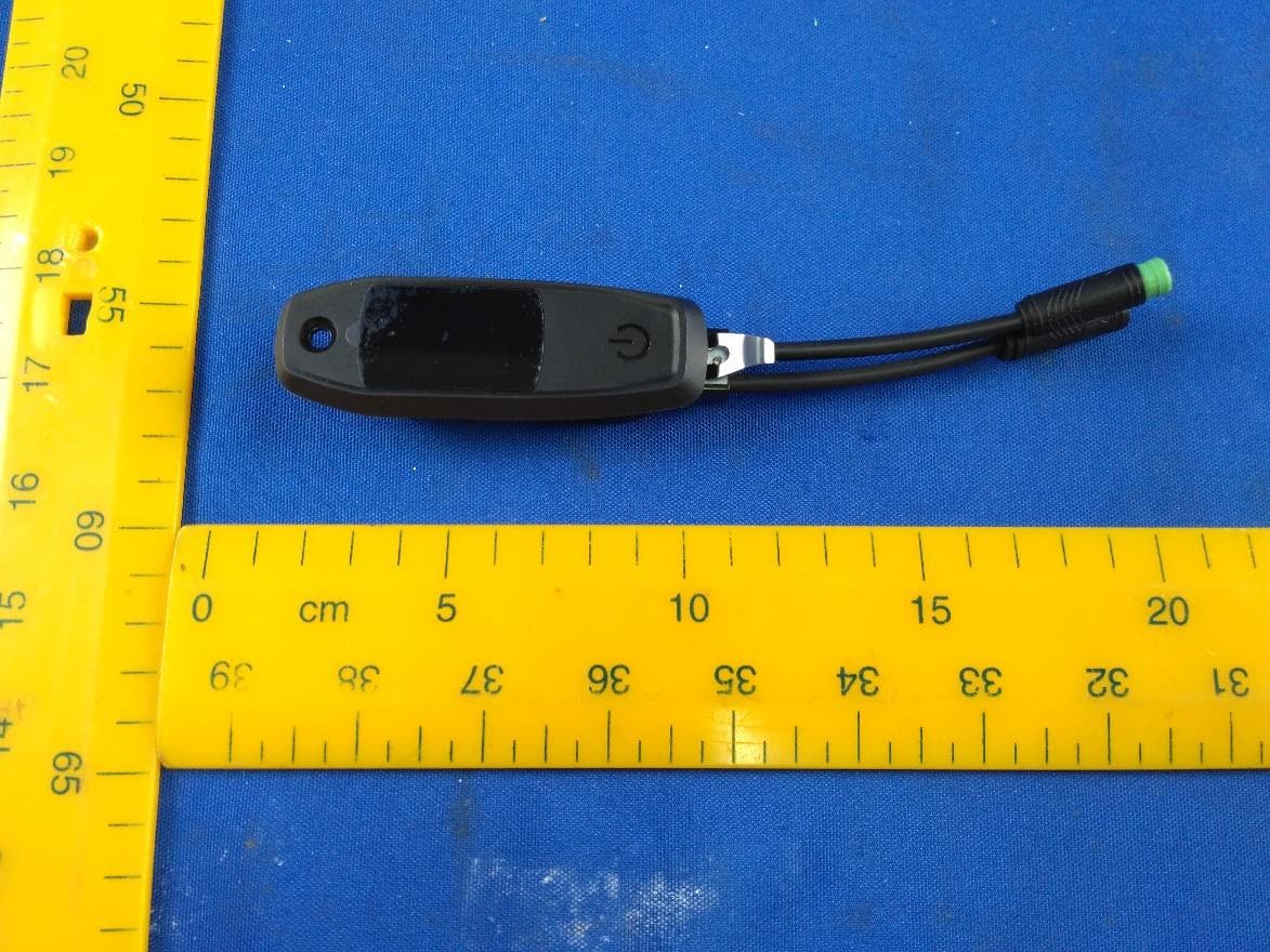
O4GTCU2
Dec 28, 2020E-Bike controller with BLE and ANT+ function
Equipment Class
DXX - Part 15 Low Power Communication Device Transmitter