O4GSMARTWTHSMART WATCH
Dayton Industrial Co., Ltd.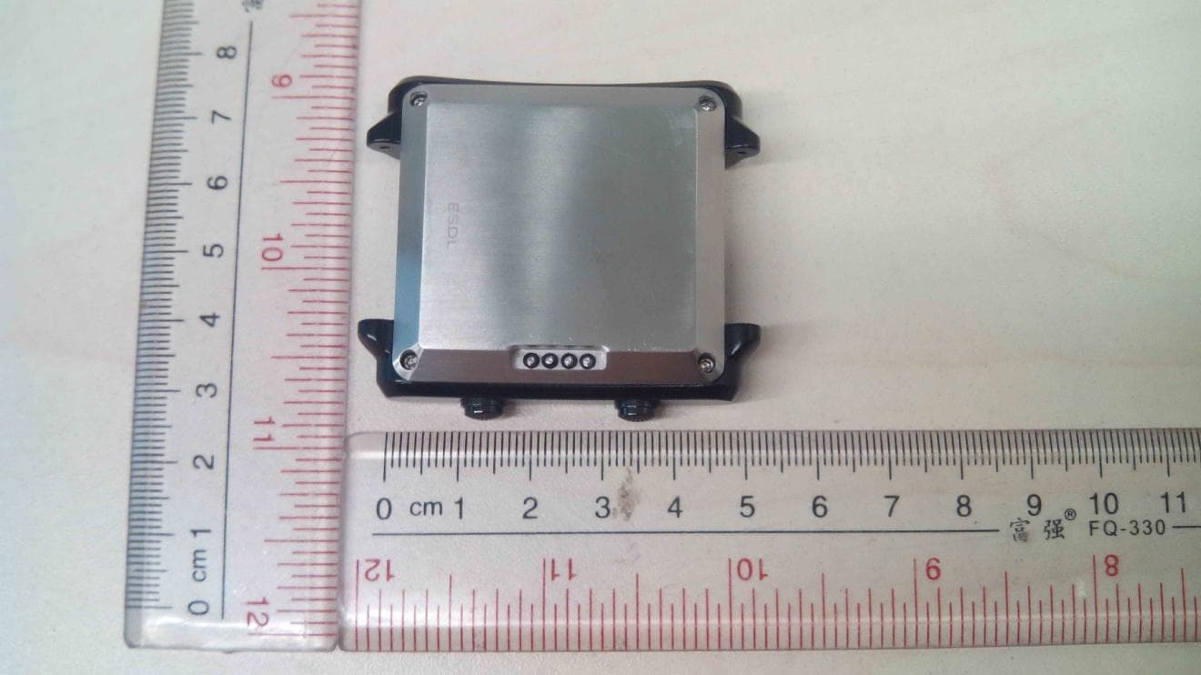
Click to zoom
Application Details
- Equipment Class
- JBP - Part 15 Class B Computing Device Peripheral
- Date of Grant
- Dec 18, 2013
- Application Purpose
- Original Equipment
- Date of Application
- Dec 18, 2013
- Equipment Note
- SMART WATCH
- Company
- Dayton Industrial Co., Ltd.
- Country
- Hong Kong
Documents & Files
Document Text
Text extracted from the exhibit documents filed with the FCC. Open a document above to read the original.
Users Manual
SURROSENSE RX ™ SYSTEM Instructions for Use SURROSENSE RX ™ SYSTEM Instructions for Use 1 The SurroSense Rx™ system is a tool to help actively prevent peripheral neuropathy complications and track progress. ©2013 Orpyx Medical Technologies Inc. All rights reserved. All trademarks and registered trademarks are the property of their respective owners. Contents of package protected by one or more U.S. patents pending (20120109013 and PCT WO/2012/055029) as well as corresponding patents in other jurisdictions. Purchase of this package does not act to grant a use license under these patents in any jurisdiction outside of the United States. Manufactured by: Orpyx Medical Technologies Inc. Calgary, AB, T2G 1R7, Canada Orpyx Customer Care Representatives Toll Free: 1-855-99ORPYX (67799) Email: [email protected] www.orpyx.com 2013 EC REP EMERGO EUROPE Molenstraat 15 2513 BH, The Hague The Netherlands 2 SURROSENSE RX ™ SYSTEM Instructions for Use SURROSENSE RX ™ SYSTEM Instructions for Use TABLE OF CONTENTS 2 1.0 The SurroSense Rx ™ 5 2.0 Symbols and Definitions 6 3.0 Setting up your system 11 4.0 Using the SurroSense Rx ™ Smartwatch 15 5.0 Orpyx Connect 16 6.0 Maintenance and Cleaning 17 7.0 Storage and Handling 18 8.0 Troubleshooting – Frequently Asked Questions 20 9.0 Regulatory Compliance Information 21 10.0 Technical Information and Specifications SURROSENSE RX ™ SYSTEM Instructions for Use 1 Peripheral neuropathy is a condition that results in loss of feeling in the feet. This inability to sense and respond to tissue damage can lead to the development of blisters and ulcers, which can lead to surgical amputation. The SurroSense Rx™ notifies the user when dangerous pressure levels are detected, so that behavior can be changed and damage avoided. The SurroSense Rx™ system is a tool to help actively prevent peripheral neuropathy complications and track progress. INCLUDED WITH PURCHASE A. SurroSense Rx™ Insert (Left and Right) B. SurroSense Rx™ Smartwatch C. SurroSense Rx™ Shoe Pod (Left and Right) D. SurroSense Rx™ Mobile App Download (not shown) 1.0 The SurroSense Rx ™ 2 SURROSENSE RX ™ SYSTEM Instructions for Use I. INTENDED USE The SurroSense Rx™ is a wearable plantar pressure monitoring system that is indicated for patients who have decreased or absent sensation in the feet resulting from a condition known as peripheral neuropathy. As the patient goes about their daily routine, data from the inserts are wirelessly transmitted to the SurroSense Rx™ smartwatch. The device can be worn both indoors and outdoors as often as desired by the patient; or as recommended by Podiatrist/ Physician. If the feedback is properly adhered to, the medical benefits of using the system may include the prevention of peripheral neuropathy-related complications including the development of blisters and ulcers, which can lead to surgical amputation. Use of the SurroSense Rx™ device does not negate the need for regular diabetic foot care with a health care professional. II. CONTRAINDICATIONS There are no known contraindications for the SurroSense Rx™ system at this time. III. WARNINGS AND PRECAUTIONS WARNING: Disregarding WARNING information may cause improper operation and inaccurate results. CAUTION: Disregarding CAUTION information may reduce the life expectancy of the product and/or damage to the product. CAUTION: This product uses and receives radio frequency signals. For proper operation, this product must be configured and operated as per the instructions provided in the manual. WARNING: This product uses low power radio communications and can affect other medical electrical; equipment. SURROSENSE RX ™ SYSTEM Instructions for Use 3 FIELD OF APPLICATION The SurroSense Rx™ was developed for everyday activities. For the necessary environmental conditions, please see Section 10.0. The SurroSense Rx™ is designed exclusively for use on one patient. In order to effectively use this device, the patient must meet the following requirements: ✔The patient must meet the physical and mental requirements with regard to the perception of alert- based feedback (acoustic signals and/or mechanical vibrations). ✔The SurroSense Rx™ is not recommended for people who are unwilling or unable to actively respond to the real-time feedback the system provides, and to adhere to the recommended maintenance and insert replacement schedule. ✔If the patient does have active skin ulceration or partial amputation, it is necessary that the patient have these wounds appropriately monitored and dressed by a healthcare professional. *Approved for patients weighing up to 136 kg/300 lbs. 4 SURROSENSE RX ™ SYSTEM Instructions for Use 2.0 Symbols and Definitions SymbolDefinition Caution Operating Instructions Manufactured By Authorized Representative (EU Only) Keep Dry Waste Electrical & Electronic Equipment CE Alert Mark Year of Manufacture EC REP EMERGO EUROPE Molenstraat 15 2513 BH, The Hague The Netherlands SURROSENSE RX ™ SYSTEM Instructions for Use 5 A. HOW TO PROPERLY FIT YOUR SURROSENSE RX™ INSERTS The SurroSense Rx™ inserts are made to fit under your existing shoe insole. Whether it’s a custom orthotic, over-the-counter or manufacturers insole, the SurroSense Rx™ insert will fit underneath. Simply remove the existing insole, and place the appropriate left or right SurroSense Rx™ insert into the shoe. The lead, (which is on the inside edge of the insert) should run along the inside of the shoe, up towards the tongue. When in place, your existing insole can be put back into the shoe on top of the SurroSense Rx™ insert. *Note: The SurroSense Rx™ should not be used with insoles that have a hard plastic heel cup as it damages the Your insole SurroSense Rx ™ insert 3.0 Setting up your system 6 SURROSENSE RX ™ SYSTEM Instructions for Use Bottom Velcro clip Bottom Lead B. HOW TO PROPERLY FIT YOUR SURROSENSE RX™ SHOE PODS The shoe pods are to be fastened on top of either a Velcro or laced shoe. For a Velcro shoe, use the clip provided. Place the clip w…
Text truncated - open the document above for the full version.
Cover Letter(s)
Dayton Industrial Co., Ltd. Nov. 30, 2013 Federal Communications Commission Authorization and Evaluation Division FCC ID:O4GSMARTWTH Confidentiality Request Pursuant to Sections 0.457 and 0.459 of the Commission’s Rules, the applicant hereby requests confidential treatment of information applied this application as outlined below: 1. Block Diagram 2. Circuit Diagram 3. Operational Description 4. Part List The above materials contain trade secrets and proprietary information not customarily released to the public. The public disclosure of these matters might be harmful to the applicant and provide unjustified benefits to its competitors. The Applicant understands that pursuant to Rule 0.457, disclosure of this Application and all accompanying documentation will not be made before the date of the Grant for this application Sincerely, Signature Name/Title: Wong Lap Fai/ Manager Applicant: Dayton Industrial Co., Ltd ADDRESS: 2-12 Kwai Fat Road, 11-A Kwai Chung, New Territories, Hong Kong TEL: 852 24224404 FAX : 852 24804627 Email: [email protected]
ID Label/Location Info
A1-5135A02 OP243
Internal Photos
Antenna
Test Report
Report No.:60.960.13.047.01 Rev:00 TÜV SÜD HONG KONG LTD. 3/F, West Wing, Lakeside 2, 10 Science Park West Avenue, Science Park, Shatin, HK. Tel: +852-2776 1323 Fax: +852-2776 1206 Page 1 of 19 FCC&IC Cerification - TEST REPORT Report Number : 60.960.13.047.01 Date of Issue: November 28, 2013 Model : OP243 Product type : Smart Watch Applicant : Dayton Industrial Co., Ltd. Address : 2-12 Kwai Fat Road, 11-A Kwai Chung, New Territories, Hong Kong Production Facility : Kendy Enterprise Ltd. Address : 2-12 Kwai Fat Road, 11-A Kwai Chung, New Territories, Hong Kong Test Result : Positive Negative Total Pages: 19 TÜV SÜD Hong Kong Ltd. is a subcontractor to TÜV Product Service, GmbH according to the principles outlined in ISO 17025. TÜV SÜD Hong Kong Ltd. reports apply only to the specific samples tested under stated test conditions. Construction of the actual test samples has been documented. It is the manufacturer's responsibility to assure that additional production units of this model are manufactured with identical electrical and mechanical components. The manufacturer/importer is responsible to the Competent Authorities in Europe for any modifications made to the production units which result in non-compliance to the relevant regulations. TÜV SÜD Hong Kong Ltd. shall have no liability for any deductions, inferences or generalizations drawn by the client or others from TÜV SÜD Hong Kong Ltd. issued reports. This report is the confidential property of the client. As a mutual protection to our clients, the public and ourselves, extracts from the test report shall not be reproduced except in full without our written approval. Prepared by: Reviewed by: __________________________________________ __________________________________________ CHAN Kwong Ngai Edmond FUNG Report No.:60.960.13.047.01 Rev:00 TÜV SÜD HONG KONG LTD. 3/F, West Wing, Lakeside 2, 10 Science Park West Avenue, Science Park, Shatin, HK. Tel: +852-2776 1323 Fax: +852-2776 1206 Page 2 of 19 TABLE OF CONTENTS 1 General Information ......................................................................................................................................... 3 1.1 Summary of Test Result ................................................................................................................... 3 1.2 Measurement Uncertainty ................................................................................................................ 3 2 EUT Description............................................................................................................................................... 4 3 Test Methodology ............................................................................................................................................ 5 3.1 Decision of Test Mode ...................................................................................................................... 5 3.2 Configuration of Test System Details ............................................................................................... 5 3.3 Test Site Environment ...................................................................................................................... 6 4 Emission Test .................................................................................................................................................. 7 4.1 Conducted Emission Measurement ................................................................................................. 7 4.2 Radiated Interference Measurement .............................................................................................. 11 Report No.:60.960.13.047.01 Rev:00 TÜV SÜD HONG KONG LTD. 3/F, West Wing, Lakeside 2, 10 Science Park West Avenue, Science Park, Shatin, HK. Tel: +852-2776 1323 Fax: +852-2776 1206 Page 3 of 19 1 General Information 1.1 Summary of Test Result FCC Rules IC Rules Description of Test Result Remark FCC§15.107 ICES-003§6.1 AC Line Conducted Emissions PASS Meet Class B limit FCC§15.109 ICES-003§6.2 Radiated Emission PASS Meet Class B limit The test results of this report relate only to the tested sample(s) identified in this report. Manufacturer or whom it may concern should recognize the pass or fail of the test result. 1.2 Measurement Uncertainty Conducted Emission The measurement uncertainty is evaluated as ± 2.26 dB. Radiated Emission The measurement uncertainty is evaluated as ± 3.19 dB. 1.3 Measurement Uncertainty Details about the Test Laboratory Test site 1 Company name: TÜV SÜD HONG KONG LTD. 3/F, West Wing, Lakeside 2, 10 Science Park West Avenue, Science Park, Shatin HK. Telephone: 852 2776 1323 Fax: 852 2776 1372 Test site 2 Company name: TMC-Telecommunication Metrology Center of M.I.I.T No 52 Hua Yuanbei Road, Haidian District, Beijing, P.R.China Report No.:60.960.13.047.01 Rev:00 TÜV SÜD HONG KONG LTD. 3/F, West Wing, Lakeside 2, 10 Science Park West Avenue, Science Park, Shatin, HK. Tel: +852-2776 1323 Fax: +852-2776 1206 Page 4 of 19 2 EUT Description Product Smart Watch Model Number OP243 Applicant Dayton Industrial Co., Ltd. 2-12 Kwai Fat Road, 11-A Kwai Chung, New Territories, Hong Kong Manufacturer Kendy Enterprise Ltd. 2-12 Kwai Fat Road, 11-A Kwai Chung, New Territories, Hong Kong I/O Port Description: I/O Port Types Q’TY Test Description 1). Charge and data port 1 Connected to PC USB port Report No.:60.960.13.047.01 Rev:00 TÜV SÜD HONG KONG LTD. 3/F, West Wing, Lakeside 2, 10 Science Park West Avenue, Science Park, Shatin, HK. Tel: +852-2776 1323 Fax: +852-2776 1206 Page 5 of 19 3 Test Methodology 3.1 Decision of Test Mode Pre-Test Mode EMC Mode 1: Data transmitting 3.2 Configuration of Test System Details Mode 1 Signal Cable Type Signal Cable Description A AC Power Cable Non-Shielded, 2.0m B AC Power Cable Non-Shielded, 2.0m C AC Power Cable Non-Shielded, 2.0m D Keyboard Cable Non-Shielded, 1.2m E Mouse Cable Non-Shielded, 1.2m F VGA cable Non-Shielded, 1.3m G USB cable Non-Shielded, 1.2m H …
Text truncated - open the document above for the full version.
Test Setup Photos
Conducted Emission Front view side view Radiated Emission Below 1 GHz front view Below 1 GHz rear view Above 1 GHz front view Above 1 GHz rear view
Contact Information
Applicant
Wong Lap Fai(Project Manager)
Test Firm
Audix Technology (Shenzhen) Co., Ltd.Smart Tsai
Technical Specifications
| # | Rule Parts | Frequency Range | Power Output |
|---|---|---|---|
| 1 | 15B | - | - |
Other Applications from Dayton Industrial Co., Ltd.
O4G387
May 19, 2026RS HMI Control
Equipment Class
DTS - Digital Transmission System
O4GHRM25
Feb 10, 2026LINK2CARE
Equipment Class
DTS - Digital Transmission System
O4GT3
Dec 16, 2023E-Bike HMI with BLE and ANT+
Equipment Class
DTS - Digital Transmission System
O4GTPMS
Jul 18, 2022SMART BIKE SENSOR with Bluetooth and ANT+ function.
Equipment Class
DTS - Digital Transmission System
O4GTCU2
Dec 28, 2020E-Bike controller with BLE and ANT+ function
Equipment Class
DXX - Part 15 Low Power Communication Device Transmitter