O4GSPPROSZ2013 Expert is a low power SRD
Dayton Industrial Co., Ltd.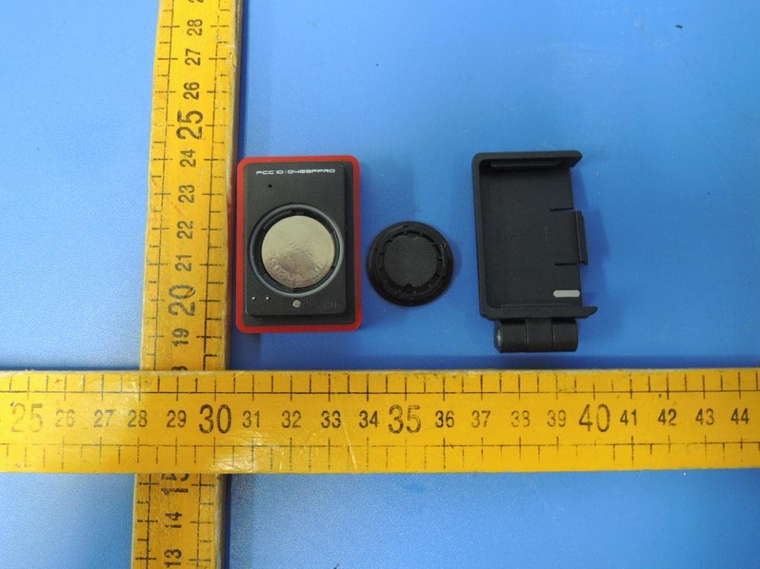
Click to zoom
Application Details
- Equipment Class
- DXX - Part 15 Low Power Communication Device Transmitter
- Date of Grant
- Jan 02, 2013
- Application Purpose
- Original Equipment
- Date of Application
- Jan 02, 2013
- Equipment Note
- SZ2013 Expert is a low power SRD
- Frequency Range
- 2450.00000000 - 2457.00000000
- Company
- Dayton Industrial Co., Ltd.
- Country
- Hong Kong
Documents & Files
Document Text
Text extracted from the exhibit documents filed with the FCC. Open a document above to read the original.
Users Manual
1 Printable manuals available at: www.specialized.com (click on: support tab) 2 Components of the Speedzone Expert 3 Installing Computer Mounts 4 Installing speed & cadence transmitter 5 Speedzone Expert user interface 6 Easy set-up and resetting 7 Using your Speedzone Expert (keyflow) 15 Re-entering the pairing sequence 16 Resetting current altitude 17 Clearing TRIP/ATM (Auto Timer) 18 Selecting Bike #1 - #2 setting 19 Re-setting the wheel/tire size 20 Manually setting wheel/tire size 21 Using the timer 23 Re-setting the clock and date 26 Heart rate zone setup 27 Re-entering calibration sequence 29 Setting power zones (auto or manual) 30 Clear memory 32 Set sampling rate 33 Linking 34 Quick PC link steps 35 Replacing the battery 36 Specifications and ranges 37 Speedzone Expert Terminology 39 Troubleshooting 40 Warranty information 41 Table of contents 3 Components of the Speedzone Expert 1. Speedzone cyclo- computer head unit 2. Cadence magnet 3. Handlebar bracket 4. Base mount 5. Steerer tube bracket 6. Speed transmitter 7. Cadence sensor 8. Spoke magnet 9. Zip ties 10. Digital heart rate strap 4 • Install the steerer tube bracket base assembly on the steerer tube. Re-install the steerer tube top cap. • Place handlebar bracket on handlebar, attach the base mount to the handlebar bracket with the included bolt. • Adjust base to desired angle with bolt adjustment. Installing Computer Mounts steerer tube bracket handlebar bracket 5 • Adjust spoke magnet so path of rotation passes along the groove area inside the sensor. IMPORTANT: Placing magnet outside the groove path may cause improper reading. • Attach the cadence magnet with self adhesive pad to the crank arm, and position the sensor’s raised line within the magnet’s rotation path. Installing speed & cadence transmitter ! 1-5mm 1/16 - 1/4 in. ! 6 Speedzone Expert user interface Digital Speed Display Secondary function display Secondary function indicator Average speed comparator Battery low indicator Bike #2 indicator Speed (10ths) Miles (English)/KM (metric) Set key Mode key Start/Stop key Power(watts)/Heartrate(BPM) *Cadence signal Bike #1 indicator *Power indicator *Heartrate signal *Heartrate indicator (when power is not paired) * Illuminated when signal is paired Setup 7 Easy set-up and resetting 2 secPRESSOR Hold “start/stop” for 2 seconds to initiate easy setup; this is only required to wake unit from shipping mode (first purchased). Wake from shipping modeReset and all clear Press reset button to enter easy set up. This will clear ride data but will not clear PC download data (memory). Blank screen indicates shipping mode 8 Setup From initial start-up: Language selection & clock setting select languageselect 12/24 hrselect hour Setup 9 ...continued clock and date setting select minuteselect yearselect month 10 Setup Wheel and tire size selection select day scroll through wheel sizes bicycle #1bicycle #2 scroll through wheel sizes for bike #2 scroll through wheel sizes scroll through wheel sizes for bike #1 (To manually set wheel size see page 20) Setup 11 Metric (km) or English (mi) & odometer select km / milesselect digitselect digit x4 km or miles 12 Setup • Max heart rate guideline: 220 minus your age • Normal power (N-PWR) = power (watts) sustained for 20-40 minutes of riding Heart rate / normal power / power zone enter max HR enter normal power auto To set manually see page 30 Setup 13 Head unit is searching for Speed, Cadence, Heart, and Power transmission signal from ANT+ digital transmitters. Pairing digital ANT+™ wireless device begin signal pairing sequence... head unit is searching for digital signals Speed / Cadence / Heartrate / Power PAIRED Clock 14 Setup begin calibrating... head unit is searching for digital signal Power device is calibrated Calibration number displayed Clock 2 sec. When “CALIB” is flashing follow instruction for calibrating your specific power meter. Calibration mode will only activate when paired with power device (see page 13). Calibrating power devices 15 Pressto access major functions Pressto access sub functions Using your Speedzone Expert (keyflow) Note: PC link function is only accessible when head unit is detached from mount bracket and used with PC download kit, sold separately. 16 Re-entering the pairing sequence Scroll to AVGSPD mode, and hold “set” key for 2 seconds. Every wireless device must be ANT+ compatible device to transmit data. 2 sec. Head unit is searching for signals (see earlier section) S - Speed C - Cadence H - Heart Rate P - Power 17 • Scroll to ALTI mode, press “set” key for two seconds. • Using the “mode” key, select each digit and confirm with the “set” key (Enter the altitude of your specific location). Resetting current altitude Note: Since altitude reading is affected by barometric pressure, re-setting altitude at known elevation before each ride is recommended to ensure accurate elevation reading. select digitselect digit 2 sec. x4 18 In “TRIP“ or “ATM“ mode, press “mode“ key for two seconds. Resetting “TRIP“ will only clear ride shown data only and PC download data is saved. Clearing TRIP/ATM (Auto Timer) 2 sec. 19 When in “TRIP“ mode, press “set“ key for two seconds. Devices (ANT+ transmitters) must be “paired” for second (bike #2) setting. Selecting Bike #1 - #2 setting 2 sec. *bicycle #1 proceeds to AVGSPD function *bicycle #2 20 *bicycle #1 *bicycle #2 activates wheel/ tire size options 2 sec • In “ODO” mode, press “mode” key for two seconds • Select desired wheel/tire size (see earlier section for details) Re-setting the wheel/tire size scroll through sizes or manually set size in mm (see page 10) scroll through sizes or manually set size in mm (see page 10) 21 (See wheel circumference calculation page 22) Manually setting wheel/tire size select digitselect digit activate 1st digit 2 sec x3 22 • Mark your tire and the ground where they meet. Roll bike forward full revolu- tion and mark the point on the floor. • Measure the distance in millimeters and ent…
Text truncated - open the document above for the full version.
External Photos
External Photos of SZ2013 Expert
Internal Photos
Report Number: 68.950.12.172.01 Page 1 of 2 Jiangsu TÜ V Product Service Ltd. – Shenzhen Branch 6 floor, H Hall, Century Craftwork Culture Square, No. 4001, Fuqiang Road, Futian District, Shenzhen 518048, P. R. China, Tel. +86 755 8828 6998, Fax: +86 755 8828 5299 Internal Photos of SZ2013 Expert Report Number: 68.950.12.172.01 Page 2 of 2 Jiangsu TÜ V Product Service Ltd. – Shenzhen Branch 6 floor, H Hall, Century Craftwork Culture Square, No. 4001, Fuqiang Road, Futian District, Shenzhen 518048, P. R. China, Tel. +86 755 8828 6998, Fax: +86 755 8828 5299 Antenna
Test Report
Report Number: 68.760.12.284 01 Page 1 of 25 Jiangsu TÜV Product Service Ltd. – Shenzhen Branch 6 floor, H Hall, Century Craftwork Culture Square, No. 4001, Fuqiang Road, Futian District, Shenzhen 518048, P. R. China, Tel. +86 755 8828 6998, Fax: +86 755 8828 5299 FCC- TEST REPORT Report Number : 68.760.12.284.01 Date of Issue: 25 December 2012 Model : SZ2013 Expert Product Type : Bicycle Computer Applicant : Dayton Industrial Co., Ltd. Address : 2-12 Kwai Fat Road, 11-A Kwai Chung, New Territories, Hong Kong Production Facility : Kendy Enterprise Ltd. Address : 2-12 Kwai Fat Road, 11-A Kwai Chung, NT, Hong Kong Test Result : Positive Negative Total pages including Appendices : 25 Jiangsu TÜV Product Service Ltd. – Shenzhen Branch is a subcontractor to TÜV SÜD Product Service GmbH according to the principles outlined in ISO 17025. Jiangsu TÜV Product Service Ltd. – Shenzhen Branch reports apply only to the specific samples tested under stated test conditions. Construction of the actual test samples has been documented. It is the manufacturer's responsibility to assure that additional production units of this model are manufactured with identical electrical and mechanical components. The manufacturer/importer is responsible to the Competent Authorities in Europe for any modifications made to the production units which result in non-compliance to the relevant regulations. Jiangsu TÜV Product Service Ltd. – Shenzhen Branch shall have no liability for any deductions, inferences or generalizations drawn by the client or others from Jiangsu TÜV Product Service Ltd. – Shenzhen Branch issued reports. This report is the confidential property of the client. As a mutual protection to our clients, the public and ourselves, extracts from the test report shall not be reproduced except in full without our written approval. Report Number: 68.760.12.284 01 Page 2 of 25 Jiangsu TÜV Product Service Ltd. – Shenzhen Branch 6 floor, H Hall, Century Craftwork Culture Square, No. 4001, Fuqiang Road, Futian District, Shenzhen 518048, P. R. China, Tel. +86 755 8828 6998, Fax: +86 755 8828 5299 1 Table of Contents 1 Table of Contents..................................................................................................... 2 2 Details about the Test Laboratory.............................................................................. 3 3 Description of the Equipment Under Test..................................................................... 4 4 Summary of Test Standards...................................................................................... 5 5 Summary of Test Results......................................................................................... 6 6 General Remarks................................................................................................... 7 7 Technical Requirements.......................................................................................... 8 7.1 Field strength of emissions and Restricted bands ................................................ 8 7.2 Out of band emissions ................................................................................. 16 7.3 20dB bandwidth............................................................................................. 22 8 System Measurement Uncertainty............................................................................ 25 Report Number: 68.760.12.284 01 Page 3 of 25 Jiangsu TÜV Product Service Ltd. – Shenzhen Branch 6 floor, H Hall, Century Craftwork Culture Square, No. 4001, Fuqiang Road, Futian District, Shenzhen 518048, P. R. China, Tel. +86 755 8828 6998, Fax: +86 755 8828 5299 2 Details about the Test Laboratory Details about the Test Laboratory Test Site 1 Company name: Jiangsu TÜV Product Service Ltd. – Shenzhen Branch 6th Floor, H Hall, Century Craftwork Culture Square, No. 4001, Fuqiang Road, Futian District 518048, Shenzhen,P.R.C. Telephone: 86 755 8828 6998 Fax: 86 755 8828 5299 Test Site 2 Company name: Audix Technology (shenzhen) Co.,Ltd Block Shenzhen, Science & Industry Park, Nantou, Shenzhen, Guangdong, China Telephone: 86 755 2663 9496 Fax: 86 755 2663 2877 Report Number: 68.760.12.284 01 Page 4 of 25 Jiangsu TÜV Product Service Ltd. – Shenzhen Branch 6 floor, H Hall, Century Craftwork Culture Square, No. 4001, Fuqiang Road, Futian District, Shenzhen 518048, P. R. China, Tel. +86 755 8828 6998, Fax: +86 755 8828 5299 3 Description of the Equipment Under Test Description of the Equipment Under Test Product: Bicycle Computer Model no.: SZ2013 Expert FCC ID: O4GSPPRO Brand Name: Dayton Options and accessories: NIL Rating: 3.0VDC (Supplied by 1 piece of CR2032 battery) RF Transmission Frequency: 2450-2457MHz Total two frequencies: 2450MHz, 2457MHz No. of Operated Channel: 2 Modulation: GFSK Duty Cycle: 0.28% Antenna Type: monopole antenna Antenna Gain: 0dBi Description of the EUT: 2.4GHz Low power communication device Auxiliary Equipment Used during Test: DESCRIPTION MANUFACTURER MODEL NO.(SHIELD) S/N(LENGTH) -- -- -- -- Report Number: 68.760.12.284 01 Page 5 of 25 Jiangsu TÜV Product Service Ltd. – Shenzhen Branch 6 floor, H Hall, Century Craftwork Culture Square, No. 4001, Fuqiang Road, Futian District, Shenzhen 518048, P. R. China, Tel. +86 755 8828 6998, Fax: +86 755 8828 5299 4 Summary of Test Standards Test Standards FCC Part 15 Subpart C 10-1-2011 Edition PART 15 - RADIO FREQUENCY DEVICES Subpart C - Intentional Radiators Report Number: 68.760.12.284 01 Page 6 of 25 Jiangsu TÜV Product Service Ltd. – Shenzhen Branch 6 floor, H Hall, Century Craftwork Culture Square, No. 4001, Fuqiang Road, Futian District, Shenzhen 518048, P. R. China, Tel. +86 755 8828 6998, Fax: +86 755 8828 5299 5 Summary of Test Results Technical Requirements FCC Part 15 Subpart C Test Condition Pages Test Site Test Result Pass Fail N/A 15.207 Conducted Emission AC Power Port --- Site 2 §15.205(a), §15.209(a), §15.249(a), §15.249(c) Field strength of emissions and Restricted bands 8 Site 2…
Text truncated - open the document above for the full version.
Test Setup Photos
Page 1 of 1 Test setup photos 1. Radiated Emission Test Blow 1GHz Above 1GHz
Contact Information
Applicant
Wong Lap Fai(Project Manager)
Test Firm
Audix Technology (Shenzhen) Co., Ltd.Smart Tsai
Technical Specifications
| # | Rule Parts | Frequency Range | Power Output |
|---|---|---|---|
| 1 | 15C | 2.45 GHz - 2.46 GHz | - |
Other Applications from Dayton Industrial Co., Ltd.
O4G387
May 19, 2026RS HMI Control
Equipment Class
DTS - Digital Transmission System
O4GHRM25
Feb 10, 2026LINK2CARE
Equipment Class
DTS - Digital Transmission System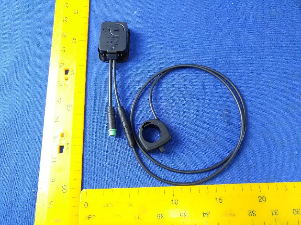
O4GT3
Dec 16, 2023E-Bike HMI with BLE and ANT+
Equipment Class
DTS - Digital Transmission System
O4GTPMS
Jul 18, 2022SMART BIKE SENSOR with Bluetooth and ANT+ function.
Equipment Class
DTS - Digital Transmission System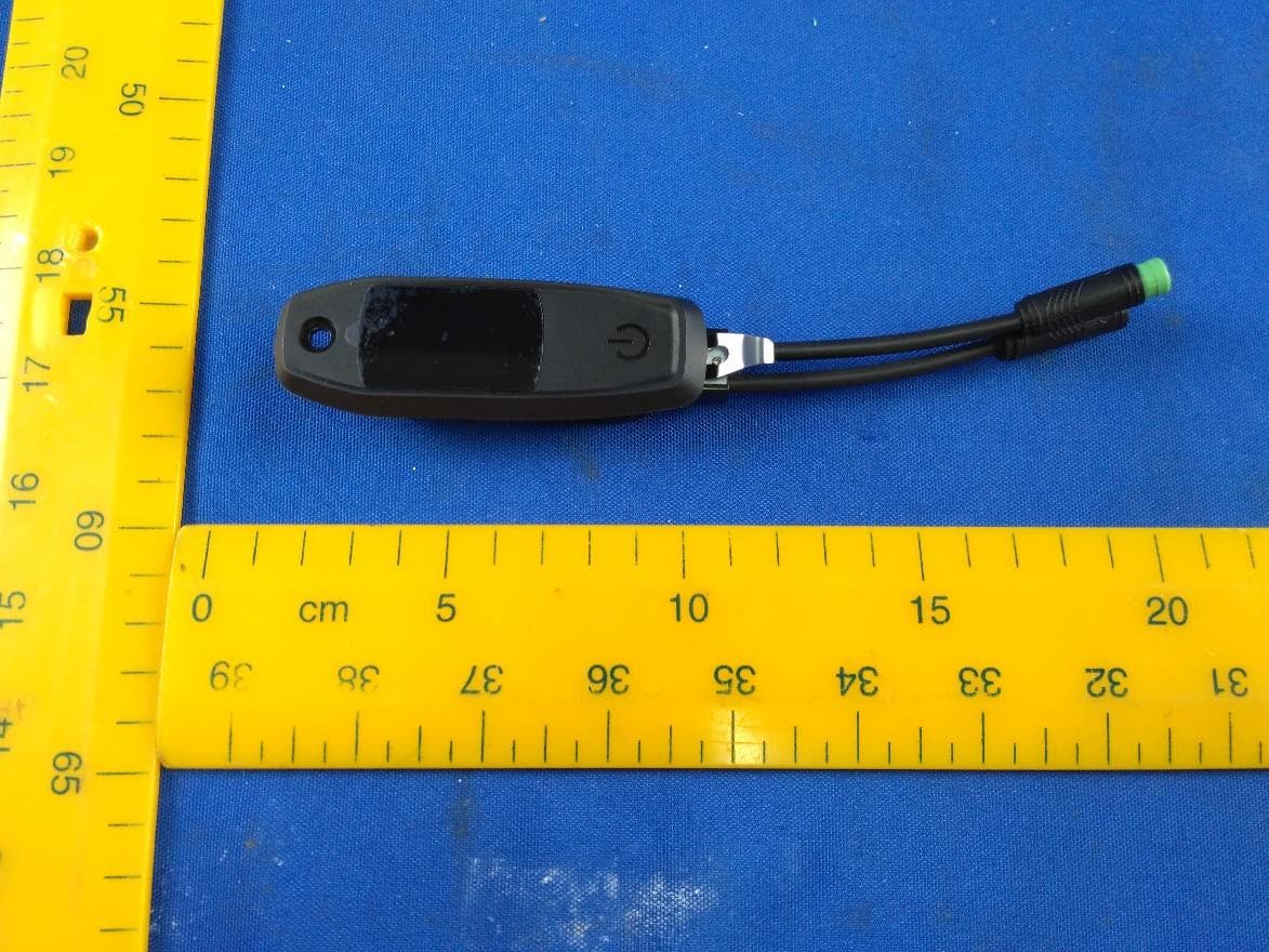
O4GTCU2
Dec 28, 2020E-Bike controller with BLE and ANT+ function
Equipment Class
DXX - Part 15 Low Power Communication Device Transmitter