O4MU922UHF Pocket Alarm Transceiver
Ascom Wireless Solutions, Inc.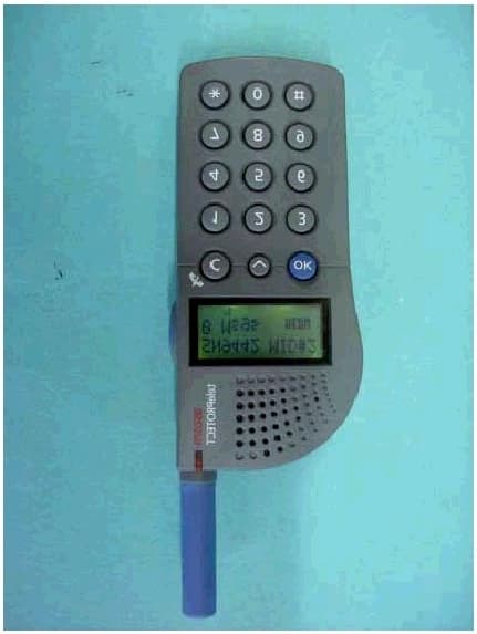
Click to zoom
Application Details
- Equipment Class
- TNT - Licensed Non-Broadcast Transmitter Worn on Body
- Date of Grant
- Jun 25, 2002
- Application Purpose
- Original Equipment
- Date of Application
- May 15, 2002
- Equipment Note
- UHF Pocket Alarm Transceiver
- Frequency Range
- 420.00000000 - 475.00000000
- Country
- United States
Documents & Files
Document Text
Text extracted from the exhibit documents filed with the FCC. Open a document above to read the original.
Users Manual
User Guide English ascom telePROTECT U922 Alarm Transceiver Enabling Group Numbers To enable/disable pagings to group numbers, press OK to enter the main menu. Press the Step-key until “Set?” is dis- played and press OK. The group numbers are displayed after your call number. Press OK to switch between On/Off. Activating Manual Absence Indication Press and hold the pre-programmed key until “Absence” is displayed. Press OK to switch between On/Off. Activating Hot-key Press and hold the pre-programmed key until the call number appears. Special Codes With special codes, supplied by the system administrator, you can send commands to your system to perform an acti- vity, for example to open a door. Enter the pre-programmed code, when “Send” is displayed, press OK. Alarm functions Note: Your unit can have functions other than described here depending on pre-programmed parameters. Push-button Alarm Always press the red alarm-button twiceor more, to trans- mit an alarm. The LED flashes once to confirm that an alarm is sent and that the transceiver is working. The alarm is transmitted silently, unless the Acoustic Location Signal (ALS) is activated. Pull-cord Alarm Snap the pull-cord fitting to the alarm transceiver. Press and hold the key to activate the alarm. Press OK to switch between On/Off. Make sure that the clip of the Pull-cord is firmly attached, for instance to your belt. If the Pull-cord is pulled off, an alarm is transmitted. NOTE: To remove the Pull-cord without triggering an alarm, the Pull-cord alarm must be deactivated. Press and hold the key . Press OK to switch Off. Man-down Alarm/No-movement Alarm Press and hold the key to activate the Man-down or the No-movement alarm. Press OK to switch between On/Off. The Man-down alarm is activated if the transceiver is tilted more than 60º. A warning signal continuously sounds after around 7 seconds. The red LED flashes once and a signal sounds to confirm that an alarm is transmitted. To prevent the alarm transmission, raise the transceiver into upright position or press the OK-button within 7 seconds, while the warning signal is heard. The No-movement alarm is activated if the transceiver has not been moved within a preset time period. Before the alarm is transmitted, a warning signal continuously sounds. If the unit has not moved during this time, the warning sig- nal sounds and an alarm is transmitted. To prevent the alarm transmission, move the unit or press the OK-button, while the warning signal is heard. Test Alarm To test the alarm transceiver and system, press the alarm button for at least one second. Distributed by: Manufactured by: Ascom Tateco AB, Sweden M0227230 Rev A Aug 1999 Ascom Tateco AB 2 2 1 ascom ascom IR-receiver Loudspeaker and Microphone Display OK-button Pull-cord Step-key C-key LED Product presentation U922 comes in three basic versions: • Alarm transceiver with limited keypad. • Alarm transceiver with one-way speech and limited keypad. • Alarm transceiver with two-way speech and full keypad. All models have advanced alarm functions and messaging. Basic functions Note: Your unit can have functions other than described here depending on pre-programmed parameters. Turning the Handset On Press OK to turn on. The unit’s identity is shown on the dis- play. To turn off, see Function settings. Receiving Text Messages A flashing LED, beep signal and the icon indicate a new message. Press OK to stop the beep signal. If Ais dis- played, you are required to acknowledge within a certain period of time. Press OK to accept/acknowledge the message. Reading Messages Press the Step-key to scroll between messages. Deleting Messages Display the message to delete, press and hold the C-key until the message is erased. Receiving Speech Calls A flashing LED, beep signal and the icon indicate an incoming speech call. Press the PTT-button to speak, release it to listen. Press and hold the C-key to end. Sending Speech Calls Enter the call number and press the PTT-button. If “Busy” is displayed, press the PTT-button twice to redial. Changing the Speaker Volume During a speech call, press the Step-key until the required volume is reached. Charging A beep signal and the icon indicate a low battery. The unit should be charged immediately. When placed in a desk- top charger, the green LED on the charger indicates a fully charged battery. In a charging rack, a steady LED on the U922 indicates a fully charged battery. Keep the unit in the charger when not in use. Location A receiver in the U922 receives and identifies the location sent from fixed locators via either infrared (IR) light or low frequency (LF) magnetic field transmission. NOTE: A U922 alarm transceiver with an IR-receiver must always be carried visibly, never covered. The IR-receiver is situated underneath the coloured transparent plastic top. Daily use To check the system, you should send a test alarm every day, see “Test alarm” under Alarm Functions. Keep the unit in the charger when not in use. Display menu Main menu “Identity”OK“Identity” Tone? Sub-menu “Identity”OKVol Set?“Call number” “Group numbers” “Identity”Time Stamp Off?Remind Beep Program? Function settings Note: Your unit can have functions other than described here depending on pre-programmed parameters. When the identity and “Menu” are shown. • Press OK to enter the main menu and to set functions. • Press the Step-key to step between the menu options. • Press the C-key once to return to the previous menu level. Switching the Audible Signal Off Press OK to enter the main menu, “Tone?” is displayed. Press OK to switch between On/Off. A flashing icon indi- cates that the signal is off. Turning the Handset Off Press OK to enter the main menu, then press the Step-key until “Off?” is displayed. Press OK. NOTE: This erases all messages, unless the Memo function (option) is active. Changing the Beep Volume Press OK to enter the main menu, press the Step-key until “Set?” is displayed. “Vol” appears. Press and hold OK until th…
Text truncated - open the document above for the full version.
Cover Letter(s)
The Jasper Group 3965 State Highway 37, Ogdensburg, New York 13669 315-375-8639 May 16, 2002 Federal Communicatio ns Co mmission 7435 Oakland Mills Road Columbia, Maryland 21046 Dear Examiner:FCC ID: O4MU922 Attached, please find our application and supporting documentation for the approval of the U922 and U922K UHF Pocket Alarm Transceiver in accordance with FCC Part 90. This application is being submitted on behalf of: Ascom Wireless Solutions, Inc. 598 Airport Boulevard, Suite 300 Morrisville, NC 27560 Should you have any questions regarding this application, please contact me at 315-375-7860 or via email at [email protected]. Tha nk yo u for yo ur assistance i n advance. Yours tr ul y, Ruth Varley The Jasper Group
External Photos
FCC ID: O4MU922EXTERIOR FRONT VIEW
External Photos
FCC ID: O4MU922EXTERIOR REAR VIEW
External Photos
FCC ID: O4MU922EXTERIOR VIEW BATTERY REMOVED
ID Label/Location Info
Label drawing and location FCC ID: O4MU922 TypeU922-AAA11234564 IC: XXXXXX-YYYYYYYY FCC ID: O4MU922 000000 Manufactured by Ascom Tateco AB, Sweden LA BEL Label will be placed on the back of the unit underneath the battery.
Internal Photos
FCC ID: OM4U922INTERIOR VIEW COMPONENT PLACEMENT
Internal Photos
FCC ID: O4MU922INTERIOR VIEW TRACE SIDE
Internal Photos
FCC ID: O4MU922INTERIOR VIEW KEYPAD AND DISPLAY
Operational Description
2000 01 25 /Rev.A1 User Manual Transceiver U922TD 91836GB User Manual Pocket Transceiver U922 This document provides a description of the pocket transceiver U922 and its functionality. The U922 is included in the teleCOURIER 900 radio paging system and the telePROTECT 900 alarm system. This User Manual describes the U922 in the default programmed version. Additional functions and factory settings are also included, providing a full description of the func- tionality. Your system may not have all functions described in this docu- ment. For information about your system, please contact your system administrator. The following documents are recommended as a supplement: • System Description teleCOURIER 900 Paging System, document number TD 91034GB. • System Description Personal Security System telePROTECT 900, document number TD 90677GB We also recommend reading the User Guide for the U922. U922 Transceiver ascom ascom 2000 01 25 /Rev.A2 User Manual Transceiver U922TD 91836GB Introduction U922 comes as either a speech transceiver, for use in the teleCOURIER 900 radio paging system, or an alarm transceiver, for use in the telePROTECT 900 alarm system. Transmission of speech and alarm is made in the UHF 425-475 or the VHF 140-175 MHz range. Paging and speech is received in the UHF 425-475 MHz range. The speech transceiver can transmit and receive voice as well as text messages, allow- ing both mobile-to-central and mobile-to-mobile calls. The alarm transceiver can, in addition to the functions of the speech transceivers, transmit different alarms. It can also receive an acknowledgement paging confirming that the alarm has been received. The alarm transceiver can be equipped with a location receiver that stores the location code transmitted by fixed LF or IR Locators. When an alarm is sent, the location codes are also sent by the transceiver to the alarm central. Another security function is that the alarm transceiver can be supervised continuously. All transceivers, except those with a LF receiver, vibrator and one-way speech transceivers without acknowledge are available in intrinsically safe versions that comply with classification EEx ib IIC T4. The unit is water resistant according to IP64. U922 Versions The U922 transceiver comes in the following basic versions: •Alarm transceiver with no-speech and 6-button keypad. •Speech/Alarm transceiver with one-way speech and 6-button keypad. •Speech/Alarm transceiver with two-way speech and full keypad. FunctionsSpeechAlarm Characters per message120120 Stored messages1010 Characters in memory480480 "Group numbers"55 Absent indicationYesYes Time StampYesYes VibratorOptionOption Keypad6/156/15 AcknowledgeOptionYes EX-classificationOptionOption Push button alarm—Yes Pull-cord alarm—Option Man-down alarm—Option No-movement alarm—Option IR-receiver—Option LF-receiver—Option 2000 01 25 /Rev.A3 User Manual Transceiver U922TD 91836GB Description Transceiver Description Symbols in the Display: New message (the symbol flashes) More than one message stored The message is longer than two lines Speech call Muted beep signal Low battery warning. Charge as soon as possible Low battery, speech transmission turned off. Charge immediately Time stamp, see the chapter Display menu functions Function and RTC, Time stamp Hot-key function activated Manual acknowledgement request I IInfo-page message The message is addressed to one of the group numbers The message is diverted from other call number Error indication, contact system administrator ascom ascom LED Push-To-Talk (PTT) Button C-key Step-key OK-key Number- and hotkeys IR Receiver Loudspeaker and Microphone Red Alarm- button (Alarm Transceiver) Display 1 2 3 A I s 2000 01 25 /Rev.A4 User Manual Transceiver U922TD 91836GB Display U922 has an alphanumerical display with 2x12 characters. Longer messages automatically scroll on the display, two lines at a time, up to 120 characters. The user can start the scrolling manually by pressing the OK button once. The display is illuminated. The text is clear and easy to read and consists of both lower and upper case characters. The system administrator can change all preprogrammed texts. Normally the display shows the identity and the text "Menu". The transceiver is programmed with an identity unique within the system. The identity can be your call number, name or other. Below this text, the icons appear. The icons keep track of activated functions and notify the user, for example, that a new message is received. If an error occurs, the Error Indication icon appears. Rescue coming Example of paging with acknowledgement message "A" Four different character sets can be used in the transceiver: • 910/910T • Full Roman • Roman+Cyrillic+Greek • Roman+Arabic+Hebrew. C-key The C-key is used to return to previous menu level, to erase paging messages and to end speech calls. Step-key The Step-key is used to scroll between messages and to step between the menu options. OK-key The Blue OK-key is used to mute and acknowledge pagings and enter the main menu to change the transceiver's settings. It is also used when storing or recalling a call number. If the function of the OK button is set to "Send", it is possible to send commands to the system to perform an activity, for example to open a door. This is done by sending special codes. The codes are supplied by the system administrator. Enter the preprogrammed code. When “Send” is displayed, press OK. Number- and Hot-keys The keys numbered 1-6 are pre-programmable Hot-keys. They are used to activate various alarm functions and to enter paging numbers. See also the section Pocket Unit Programmer. Keys numbered 7-9 are only used to enter paging numbers. A 2000 01 25 /Rev.A5 User Manual Transceiver U922TD 91836GB Red Alarm-button The alarm transceivers are equipped with a red alarm-button. It is used to transmit alarms and to test the alarm transceiver and the system. Red light-emitting diode Indicates that an alarm/message is sent, and a mes…
Text truncated - open the document above for the full version.
Operational Description
2000-02-24 TD 91930GB Alarm Transceiver U922K General The U922K transceiver is used in the Personal Secu- rity System. The receiver operates in the UHF range, while the transmitter can operate either in the UHF or VHF range. The transceiver can transmit and receive voice and text messages, transmit alarms and receive acknowledgement pagings. Versions U922K is a two-way speech alarm transceiver with 15 button keypad. As an option the unit can be equipped with a receiver for location codes sent via infrared signals, LF magnetic field or both. For a more detailed description of different versions, please contact your Ascom product distributor. Applications Pagings When a paging is received the user is alerted by tone, light and vibration (optional). One of seven different alert signals can be received. Each one is programmable in the transceiver. Typical examples are ring signal and siren. In silent mode the speaker is disconnected. Alarm pagings override the silent mode. If messages are not acknowledged, a beep is heard every minute as a reminder. The ten most recent messages are saved in the memory. Call number on/off function activates or deactivates up to five of the six call numbers. Most internal functions can be customized individually for each transceiver. Several built-in test functions ensure proper func- Features • Manual and automatic alarm • Location function • Two-way data (receives text messages; transmits alarms or acknowledgements) • Two-way speech • Tone and display messages • 24 character LCD display with back lighting • Up to 120 characters per message • Up to 10 displayable stored messages • Personal settings stored in removable SIM-card, which is reprogrammable in charger or via radio • Accumulator in special pack, both NiMH and NiCd available • Intrinsically safe or vibrator version as option System dependent: • Time-stamped messages • Surveillance as option • Can be used in a "Geprüfte Sicherheit-system" tion. Both internal and system functions are super- vised. Alarms The push-button alarms can always be operated. Pulling the pull-cord, fitted to the base of the transceiver, activates a pull-cord alarm. A no-movement alarm is activated if the transceiver has not been moved within a pre-set time period. Before the alarm is transmitted, a warning signal continuously sounds. The alarm transmission is pre- vented if the unit is moved or the OK-button is pressed while the warning signal is heard. A man-down alarm is activated when the unit is tilted more than 60°± 10° from upright position. The transceiver can have either no-movement alarm or man-down alarm, not both. The supervision function enables the system to continuously check if the unit works properly. It is enabled or disabled when the unit is removed or placed in a storage rack. It is also possible to attach an external alarm. Speech Calls are answered by pressing the transmit button. When starting a call from the 922 a busy tone sounds if the channel is occupied. When the channel is available an alert tone sounds. The call can be restarted by pushing the transmit button. Technical specifications are listed on the following page. 2000-02-24 TD 91930GB Technical Specifications Dimensions124 x 51 x 19 mm excl. antenna. Display: 55 x 23 mm CasePC/ABS, grey Keypad15 Buttons + Alarm + Talk Weight150 g incl. battery Sound pressure level> 100 dBA at 10 cm (bleep) Temperature range–10 to +55°C Display2 x 12 character DOT Matrix LCD Character capabilityRoman + Extended Roman / Roman+Cyrillic-Greek / Roman + Hebrew + Arabic Battery typeSpecial pack with either NiMH or NiCd cells Battery time, min2 h (Transmitter on continuously) Battery time, max96 h (No pagings, Battery Save Time at 0,5 s, Location Read Interval at 0,5 s and not within the coverage area of a locator) WaterproofEN60529, IP64 Shock resistantIEC 68-2-32, procedure 1, dropped from 1 meter 12 times Radio section Frequency range420 - 470 MHz (Rx), 149.8–151.1, 159–161.2, 170.5–170.8, 420 - 475 MHz (Tx) FSK modulation, both Rx and Tx3 kHz deviation at 20 and 25 kHz channel spacing 1.5 kHz deviation at 12.5 kHz channel spacing Adj. channel selectivityComply with ETS 300 224 and 300 220 Spurious response rejectionComply with ETS 300 224 and 300 220 Spurious emissionComply with ETS 300 224 and 300 220 Sensitivity10 μV/m at 3 kHz deviation AntennaHelical Radiated Power> 10 mW ERP IR Receiver Section Carrier frequency39.6 kHz Sensitivity25 nW/cm 2 at 950 nm > 17 m line of sight from IR locator (100 mW/sr) LF Receiver Section Carrier frequency39.6 kHz Sensitivity30 μA/m 3 m in free space when the LF-locator is set to max. range Options • Intrinsically safe version Handsets without vibrator and location function via LF magnetic field are available in intrinsically safe version (EX-version) according to EEx ib IIC T4 standard • Vibrator (Note: Vibrator cannot be combined with Man-down or No-movement alarm) • Pull-cord alarm • Man-down or No-movement alarm Accessories • Safety cord • Leather holder Specifications are subject to change without notice.
Parts List/Tune Up Info
1 40374H-1 C977 R979 C979R972 C981 C980 R971 R969 R970 R944 C957 C956 C950 C954 C953 C952 C951 R943 R942 R941 R940 R938 R973 C970 C968 C966 R957 R956 C978 C969 C967 R948 C965 C963 R954 C976 C975 R937 C927 C930 C929 C926 C925 C932 R930 R925 R927 R928 R929 R931 C974 R955 C962 C944 C960 C961 R952 R947 R926 R951 R949 R950 R953 C958 C973 C959 C943 R939 C948 C933 C945 R960 C947 C946 C330R321 R316 C329 C322 R320 R323 C318 R325 C334 C325 C328 R318 C327 R319 R317 C304 R322 C983 R341 R326 C985 R980 C982 R342 C987 C310 C303 C332 C326 C356 R324 C333 R978 C339 C305 C338 X925 C155 L151 L TR928 TR935 TR927 TR930 TR929 TR304 TR303 TR305 TR307 D925 D928 J925 TR925 TR926 D150 IC926 L935 L933 L931 R959 L934 L932 R958 C964 L927 C942 C949 L309 L310 L311 L301 L303 C357 L936 C324 C331 C335 C336 C309 C300 C955 C928 C344 R315 R946 L150 FL302 Z151 L308 C358 IC927 Z150 C984 C150 C154 X302 X301 FL301 D926 D927 P925 J301 L305 R945 X926 J926 J927 TOP AND BOTTOM SIDE 1 1 COMPONENT LAYOUTUHF DCDC,RX,TX-UNITS 40374H 60343H 10627*,10629* 922RU PvH/BKv/MM ( ) GOTEBORG SWEDEN ascom Tateco H 990407 OS G 990125 OSN M L K J I DRAWING NUMBERPCB NUMBER F 961127 LE D 960219 LE C 951024 P/B/M B 941215 MM STAT:A 940613 MM SHEET E ELECTRICAL DIAGRAM SCALE DESIGNED/DRAWN APPROVED 1 VL LMH 922RU 40374H-4 NB IC150 TR150 C971 C972 S343 IC925 R961 IC300 R962 L926 L925 C351 TR931 TR932 TR934 TR933 TR302 TR306 TR300 C936 C986 C354 L304 L302 C934 R963 L937 C353 R981 R982 R964 R967R968 R965 R966 C935 R932 C937 C941 C940 C938 R936 R935 R934R933 C939 C349 C347 C348 C350 C346 R333 R334 R335 C345 R336 R339 R332 C343 R330 R337 R338 R303 C308 C306 R310 C314 R312 C315 R314 R306 R305 C337 C311 R307 C312 C320 C321 R311 C316 C307 R308 R309 C317 C313 R313 R329 C301 R_FD_M R_FD_VL C931 R340 R328 R343 R304 R977 R976 R975 R974 R_FD_LR_FD_H C352 -+ 1 IC928
Schematics
L152 22U C939 10N C943 1N0 C959 10P C942 1U0 R153 M15 C961 1NO C960 1N0 C962 1N0 C974 39P C983 27P C938 N47 C940 N56 C941 N33 C937 N33 SW GND LBOLBIVC VIN SHDN FB IC150 LT1308 123 4 56 78 C976 NM C963 N68 C965 1N0 C964 U10 C967 10N C969 22N C966 1N0 C968 22N C970 27P C935 U10 C972 1N0 C971 1N0 R928 10K C975 N33 C979 12P C977 NM R929 K10 C982 1N0 C988 27P C951 N10 C944 U10 C945 N10 C946 47N C930 1U0 R959 NTC4K7 C929 U10 C928 N10 C927 10N C926 10N C933 N10 C925 10N C934 1U0 C932 N10 R953 3K9 R950 2K2 R949 3K9 R951 2K7 R947 K15 R952 K10 R955 1K8 R933 39K R934 39K R935 47K R936 47K R937 22K R954 K10 R948 K10 R960 1K2 R956 2K7 R957 1K0 R973 NM R932 10K R980 1K0 R982 1R0 R966 4K7 R965 M10 R968 4K7 R967 M10 R964 M10 R963 4K7 R962 M10 R961 4K7 R970 2K7 R969 4K7 C973 N33 C978 N68 R981 1R0 R974 M10 R976 3K9 R975 K22 R979 0R0 R946 M10 R927 2K2 R926 1K0 R925 K39 R945 2K7 C980 10P S950 +5V +4V +4V + C155 22U R971 2K7 C989 NM +4V L939 27N D950A BAS28 41 +4V P925 2K2 L938 82N L926 3U3 L932 82N L934 U10 L941 82N R151 M10 R150 M15 D150 BYS10-45 L150 22U +4V L937 FD +5V L940 82N D950B BAS28 32 VOUT BYPASS GND CTRLVIN IC925 TK11240 1 2 34 6 + C936 4U7 R958 1K0 + C154 68U + C150 22U + C986 4U7 +4V +4V +4V +4V +4V IC928A ICL7621 23 84 1 IC928B ICL7621 65 84 7 C153 U10 C152 22N J925 J926 J927Z151 5.6V Z150 5.6V C151 U10 VTRF MODVCC IC931 VCO 123 4 GND VCC OUT VCONT IC929 TCXO 123 4 C990 8P2 TR934 BC858CW TR932 BC858CW TR931 BC848CW TR933 BC848CW TR935 BFS520 TR928 BFS520 TR929 BFS540 TR930 BLT50 VCCD FO/LD LEVP DATA CLOCK CE GNDD OSCINVCCAFINFIN GNDAGNDCPCPOFLO IC930 LMX2306 12 9 10 3 11 4 12 8 13 56 1415 7 16 R152 47K L942 FD +4V L936 NM C948 U10 C950 U10 C949 N10 +4V VBAT C931 NM + C947 4U7 E 980904 OS D 980527 LE C 980323 LE B 980129 OS STAT:A 980128 OS FG DRAWING NUMBERPCB NUMBER SHEET COMPONENT LAYOUT APPROVED DESIGNED/DRAWN SCALE NM 56N Frequency dependent Components (FD): NM=Not mounted 12N 33N NM 56N L942L937 170MHz 160MHz 150MHz TO RX ,5 GND CONTACT GND HELICAL ANTENNA CONTACT PROTECTION ESD- TX ON +SUBTONE 18765432 CODE+SPEECHTX POWER ON TX ON +4V PLL ENABLE PLL CLOCK PLL DATA CONVERTER +5V FROM DC/DC CONVERTER +5V FROM DC/DC 2.0VDC 2.0VDC DC/DC REGULATOR VOLTAGE PASS FILTER AUDIO LOW BUFFER HARMONIC FILTER ANTENNA SWITCH POWER AMPLIFIER 10715E 922RU2 40462*60422* RL/OS ascom Tateco GOTEBORG SWEDEN TX AND DCDC-UNITSELECTRICAL DIAGRAM ( 11)
Test Report
CETECOM ICT Services GmbH Radio Satellite Communication Untertürkheimer Straße 6-10 . D-66117 SaarbrückenTelefon: +49 (0)681 598-9100Telefax: -9075 RSC14issue test report consist of 64 PagesPage 1 (64) TTI-P-G166/98-30 Accredited Bluetooth™ Test Facility (BQTF) Test report no.: 2_2816-01-01/02 FCC Part 2, 15, 90 / RSS-119 U922K / U922xx CETECOM – ICT Services GmbH Untertürkheimerstr. 6-10 66117 Saarbrücken, Germany Telephone: + 49 (0) 681 / 598-0 Fax: + 49 (0) 681 / 9075 BLUETOOTH is a trademark owned by Bluetooth SIG, Inc. and licensed to CETECOM CETECOM ICT Services GmbH Test report nr.:2_2816-01-01/02Issue date: 2002-02-19Page 2 (64) Table of Contents 1 General information 1.1 Notes 1.2 Testing laboratory 1.3 Details of applicant 1.4 Application details 1.5 Test item 1.6 Test standards 2 Technical test 2.1 Summary of test results 2.2 Test report 1 General information 1.1 Notes The test results of this test report relate exclusively to the test item specified in 1.5. The CETECOM ICT Services GmbH does not assume responsibility for any conclusions and generalisations drawn from the test results with regard to other specimens or samples of the type of the equipment represented by the test item. The test report may only be reproduced or published in full. Reproduction or publication of extracts from the report requires the prior written approval of the CETECOM ICT Services GmbH. 1.2Testing laboratory CETECOM ICT Services GmbH Untertürkheimer Straße 6 - 10 66117 Saarbrücken Germany Telefone: + 49 681 598 - 9100 Telefax : + 49 681 598 - 9075 E-mail : [email protected] Internet : www.cetecom.de Accredited testing laboratory DAR-registration number : TTI-P-G 166/98-30 Accredited Bluetooth™ Test Facility (BQTF) BLUETOOTH is a trademark owned by Bluetooth SIG, Inc. and licensed to CETECOM CETECOM ICT Services GmbH Test report nr.:2_2816-01-01/02Issue date: 2002-02-19Page 3 (64) 1.3Details of applicant Name : Ascom Tateco AB Street : Grimbodalen 2, P.O.Box 8783 City : SE-40276 Göteborg Country : Sweden Telephone : +46 –31 – 559 302 Telefax : +46 –31 – 559 031 Contact : Mr. Thomas Harju Telephone : +46 –31 – 559 302 1.4Application details Date of receipt of application : 14.02.2002 Date of receipt of test item : 18.02.2002 Date of test : 18.-.19.02.2002 1.5Test item Type of equipment : Pocket alarm transceiver Type designation: U922K / U922xx Manufacturer: applicant Street: City: Country: Serial number: 4719443; 4719442; 4719335 Additional information : Frequency: 445 - 470 MHz Type of modulation: 10K0F1D / 10K0F3E Channel separation: 12.5 kHz Number of channels : 1 Antenna: Helix antenna Power supply: 2,6V NiMH accu Output power: Conducted: max. 46.6mW / ERP: 33.1mW Type of equipment: Temperature range : -30°C - +60°C Max. Frequency deviation : Speech: 2.11 kHz Data: 1.88 kHz 1.6Test standards: FCC Part 2, 15, 90 CETECOM ICT Services GmbH Test report nr.:2_2816-01-01/02Issue date: 2002-02-19Page 4 (64) 2 Technical test The radiated measurements were performed vertical andhorizontal over the whole frequency range.We start at 1 m high with vertical receiving antenna and rotate the dish continuously. During rotation we use the antenna lift system to vary the high from 1 to 4 m. So we find maximum radiation output. At this points we do manual remeasurements. After this we do the same measurements in horizontal position of the receiving antenna. This (horizontal and vertical) is made for all the three planes of the test sample. We use the maximum received results. The detector function and selection of bandwidth are according ANSI C63.2-1996 item 8.2.1 and ANSI C63.4-1992 Item 4.2. Antennas are conform with ANSI C63.2-1996 item 15. 150 kHz - 30 MHz: Quasi Peak measurement, 9kHz Bandwidth, passive loop antenna. 30 MHz - 200 MHz: Quasi Peak measurement, 120KHz Bandwidth, biconical antenna 200MHz - 1GHz: Quasi Peak measurement, 120KHz Bandwidth, log periodic antenna 1GHz: Average, RBW 1MHz, VBW 10 MHz, waveguide horn 2.1Summary of test results No deviations from the technical specification(s) were ascertained in the course of the tests performed. Final verdict : PASS The Equipment meets also the requirements of the RSS-119 (Canada) Technical responsibility for area of testing : 27.02.02RSC 8411 Berg M. DateSectionNameSignature Technical responsibility for area of testing : 27.02.02RSC8414Ames H. DateSectionNameSignature CETECOM ICT Services GmbH Test report nr.:2_2816-01-01/02Issue date: 2002-02-19Page 5 (64) 2.2Test report TEST REPORT Test report no. : 2_2816-01-01/02 CETECOM ICT Services GmbH Test report nr.:2_2816-01-01/02Issue date: 2002-02-19Page 6 (64) TEST REPORT REFERENCE LIST OF MEASUREMENTS PARAMETER TO BE MEASUREDPAGE RF Power Vs. DC Power Input SUBCLAUSE § 2.9937 OCCUPIED BANDWIDTH §2.9898 MAXIMUM PEAK OUTPUT POWER SUBCLAUSE § 2.104617 CONDUCTED SPURIOUS EMISSIONS § 2.99121 RADIATED SPURIOUS EMISSION §2.99325 FREQUENCY STABILITY Vs. TEMPERATURE § 2.99532 FREQUENCY STABILITY Vs. VOLTAGE § 2.99135 TRANSIENT FREQUENCY BEHAVIOR §90.21438 RECEIVER SPURIOUS RADIATION § 15.20942 RECEIVER SPURIOUS EMISSIONS (radiated) § 15.20943 RECEIVER SPURIOUS EMISSIONS (conducted) § 15.11145 Conducted emissions § 15.107/20748 TEST EQUIPMENT AND ANCILLARIES USED FOR TESTS50 Photographs of the equipment52 CETECOM ICT Services GmbH Test report nr..: 2_2816-01-01/02Issue Date: 2002-02-19Page 7 (64) Equipment under test : U922K / U922xx Ambient temperature : 23.0° °° °C Relative humidity : 31% REFERENCE NUMBER(S) OF TEST EQUIPMENT USED (for reference numbers see test equipment listing) - RF Power Vs. DC Power InputSUBCLAUSE § 2.993 Power (W) Frequency445.0125 MHz 457.500 MHz 469.9875 MHz Power consumption0.650.6750.65 Measurement uncertainty± 3 % CETECOM ICT Services GmbH Test report nr..: 2_2816-01-01/02Issue Date: 2002-02-19Page 8 (64) Equipment under test : U922K / U922xx Ambient temperature : 23.0° °° °C Relative humidity : 31% REFERENCE NUMBER(S) OF TEST EQUIPMENT USED (for reference numbers see test e…
Text truncated - open the document above for the full version.
Test Report
CETECOM ICT Services GmbH Test report no.: 2_1721-C/99Issue Date: 20.10.1999Page 19 (48) Equipment under test : telePROTECT U922X Ambient temperature: 23°C Relative humidity : 47 % REFERENCE NUMBER(S) OF TEST EQUIPMENT USED (for reference numbers see test equipment listing) 17 - 24 TRANSMITTER SPURIOUS EMISSIONS RADIATED SUBCLAUSE 8.5 Power level at which the measurement has been performed : 6,76 / 12,88 / 15,85 mW Transmitter operatingModulated/Unmodulated* *(Delete whichever is inappropriate) SPURIOUS EMISSIONS LEVEL (nW) 420,00 MHz447,50 MHz475,00 MHz f (MHz) Band- width (kHz) Level (nW) f (MHz) Band- width (kHz) Level (nW) f (MHz) Band- width (kHz) Level (nW) 2100,010087,0895,0100114,8950,0100151,3 2520,010012,51342,510013,41425,010031,6 2237,510022,92850,010018,1 2685,010013,8 3132,510012,0 Measurement uncertainty± 3dB Bandwidth (kHz); this refers to the bandwidth of the measurement receiver LIMIT 5.1.5 Table 3 Frequency range30 MHz to 1 GHz>1 to 4 GHz or >1 to 12.75 GHz (see clause 8.5.2 b) Transmitter operating0,25 μW (-36.0 dBm)1,00 μW (-30.0 dBm) CETECOM ICT Services GmbH Test report no.: 2_1721-C/99Issue Date: 20.10.1999Page 20 (48) Equipment under test : telePROTECT U922X Ambient temperature: 23°C Relative humidity : 47 % REFERENCE NUMBER(S) OF TEST EQUIPMENT USED (for reference numbers see test equipment listing) 01 , 02 , 05 TRANSMITTER SPURIOUS EMISSIONS RADIATED SUBCLAUSE 8.5 Power level at which the measurement has been performed : 6,76 / 12,88 / 15,85 mW Transmitter standbyModulated/Unmodulated* *(Delete which…
Text truncated - open the document above for the full version.
Contact Information
Applicant
Mats Espling(Director of International R&D)
Technical Contact
Ascom Wireless Solutions, Inc.Bo Eriksson
[email protected]919-861-6600
598 Airport Boulevard, Suite 300 · Morrisville, North Carolina · United States
Non-Technical Contact
The Jasper GroupRuth Varley
[email protected]315-375-7860
Test Firm
Cetecom ICT Services GmbHRalf Hoehn
Technical Specifications
| # | Rule Parts | Frequency Range | Power Output | Emission | Tolerance |
|---|---|---|---|---|---|
| 2 | 90.21 | 420 MHz - 475 MHz | 46.00 mW | 10K0F3E | 2.46 ppm |
Other Applications from Ascom Wireless Solutions, Inc.
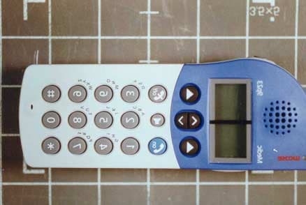
O4M9P23
Apr 27, 2003Portable Telephone
Equipment Class
PUE - Part 15 Unlicensed PCS portable Tx held to ear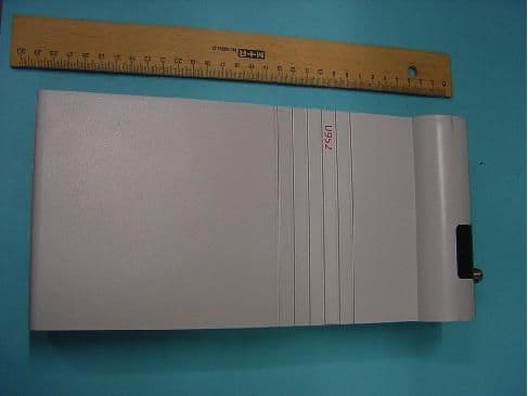
O4MU952T
May 15, 2002UHF Base Station Fixed Transmitter
Equipment Class
TNB - Licensed Non-Broadcast Station Transmitter