O55-LR2172R2
SWAGTEK
Click to zoom
Application Details
- Equipment Class
- PCE - PCS Licensed Transmitter held to ear
- Date of Grant
- Aug 30, 2015
- Application Purpose
- Original Equipment
- Date of Application
- Aug 30, 2015
- Equipment Note
- R2
- Frequency Range
- 1850.20000000 - 1909.80000000
- Company
- SWAGTEK
- Country
- United States
Documents & Files
Document Text
Text extracted from the exhibit documents filed with the FCC. Open a document above to read the original.
Users Manual
This device complies with Part 15 of the FCC Rules. Operation is subject to the following two conditions: (1) this device may not cause harmful interference, and (2) this device must accept any interference received, including interference that may cause undesired operation. Changes or modifications not expressly approved by the party responsible for compliance could void the user's authority to operate the equipment. NOTE: This equipment has been tested and found to comply with the limits for a Class B digital device, pursuant to Part 15 of the FCC Rules. These limits are designed to provide reasonable protection against harmful interference in a residential installation. This equipment generates, uses instructions, may cause harmful interference to radio communications. However, there is no guarantee that interference will not occur in a particular installation. If this equipment does cause harmful interference to radio or television reception, which can be determined by turning the equipment off and on, the user is encouraged to try to correct the interference by one or more of the following measures: -- Reorient or relocate the receiving antenna. -- Increase the separation between the equipment and receiver. -- Connect the equipment into an outlet on a circuit different from that to which the receiver is connected. -- Consult the dealer or an experienced radio/TV technician for help. SAR Information Statement Your wireless phone is a radio transmitter and receiver. It is designed and manufactured not to exceed the emission limits for exposure to radiofrequency (RF) energy set by the Federal Communications Commission of the U.S. Government. These limits are part of comprehensive guidelines and establish permitted levels of RF energy for the general population. The guidelines are based on standards that were developed by independent scientific organizations through periodic and thorough evaluation of scientific studies. The standards include a substantial safety margin designed to assure the safety of all persons, regardless of age and health. The exposure standard for wireless mobile phones employs a unit of measurement known as the Specific Absorption Rate, or SAR. The SAR limit set by the FCC is 1.6 W/kg. * Tests for SAR are conducted with the phone transmitting at its highest certified power level in all tested frequency bands. Although the SAR is determined at the highest certified power level, the actual SAR level of the phone while operating can be well below the maximum value. This is because the phone is designed to operate at multiple power levels so as to use only the power required to reach the network. In general, the closer you are to a wireless base station antenna, the lower the power output. Before a phone model is available for sale to the public, it must be tested and certified to the FCC that it does not exceed the limit established by the government adopted requirement for safe exposure. The tests are performed in positions and locations (e.g., at the ear and worn on the body) as required by the FCC for each model. The highest SAR value for this model phone when tested for use at the ear is 1.16 W/Kg and when worn on the body, as described in this user guide, is 0.69 W/Kg (Body-worn measurements differ among phone models, depending upon available accessories and FCC requirements). While there may be differences between the SAR levels of various phones and at various positions, they all meet the government requirement for safe exposure. The FCC has granted an Equipment Authorization for this model phone with all reported SAR levels evaluated as in compliance with the FCC RF exposure guidelines. SAR information on this model phone is on file with the FCC and can be found under the Display Grant section of http://www.fcc.gov/ oet/fccid after searching on FCC ID: O55-LR2172 Additional information on Specific Absorption Rates (SAR) can be found on the Cellular Telecommunications Industry Asso-ciation (CTIA) web-site at http://www.wow-com.com. * In the United States and Canada, the SAR limit for mobile phones used by the public is 1.6 watts/kg (W/kg) averaged over one gram of tissue. The standard incorporates a sub-stantial margin of safety to give additional protection for the public and to account for any variations in measurements. Body-worn Operation This device was tested for typical body-worn operations. To comply with RF exposure requirements, a minimum separation distance of 15mm must be maintained between the user’s body and the handset, including the antenna. Third-party belt-clips, holsters, and similar accessories used by this device should not contain any metallic components. Body-worn accessories that do not meet these requirements may not comply with RF exposure requirements and should be avoided. Use only the supplied or an approved antenna.
Cover Letter(s)
August 12, 2015 Nemko Canada Inc 303 River Road Ottawa, Ontario, Canada K1V 1H2 Attn: Director of Certification Authority to Act as Agent On our behalf, I appoint Shenzhen Alpha Product Testing Co., Ltd. Address: Building B, East Area of Nanchang Second Industrial Zone, Gushu 2nd Road, Bao'anDistrict, Shenzhen 518126,P.R.China Person: Mark Zhu (Name and address,person). to act as our agent in the preparation of this application for equipment certification. I certify that submitted documents properly describe the device or system for which equipment certification is sought. I also certify that each unit manufactured, imported or marketed, as defined in the Federal Communications Commission’s regulations will have affixed to it a label identical to that submitted for approval with this application. For instances where our authorized agent signs the application for certification on our behalf, I acknowledge that all responsibility for complying with the terms and conditions for certification, as specified by Nemko Canada Inc, still resides with SWAGTEK Address: 10205 NW19th Street,STE101 Miami, FL, 33172 USA ( applicant name and address). Signature: Name Charles Cheng Position Manager Company Name SWAGTEK Address 10205 NW19th Street,STE101 Miami, FL, 33172 USA Tel 1-305 421 9938 Fax 1-305 471 9011 Email [email protected]
Cover Letter(s)
August 12, 2015 Equipment Autorisation Division Federal Communications Commission 7435 Oakland Mills Road Columbia, MD 21046 FCC ID: O55-LR2172_ Product Name: R2 Request for Confidentiality Pursuant to Sections 0.457 and 0.459 of the commissions rules, we hereby request that the following documents be held confidential: Schematics Long-term confidential Block diagram Long-term confidential Operation description Long-term confidential Tune up procedure Long-term confidential These materials contain trade secrets and proprietary information and are not customarily released to the public. The public disclosure of this information might be harmful to the company and provide unjustified benefits to our competitors. Signature: Name Charles Cheng Position Manager Company Name SWAGTEK Address 10205 NW19th Street,STE101 Miami, FL, 33172 USA Tel 1-305 421 9938 Fax 1-305 471 9011 Email [email protected]
Cover Letter(s)
Ersteller: D. Brandhorst Revision: 00 Erstelldatum: 07.03.2008 Datum: 00.00.00 Seite 1 von 1 Swagtek Date: August 12, 2015 FCC ID: O55-LR2172 Subject: Attestation Letter “Declaration of Conformity” Dear Sirs, Our products with the above FCC ID are defined as composite device. The transmitter is authorized under the “Certification” procedure. The device is also defined as “PC Periphery” acc to §15.101 Equipment authorization of unintentional radiators, where we hereby declare, that we apply and follow the “Declaration of Conformity” procedure. If you have any questions, please feel free to contact me at the address shown below. Yours sincerely, Name Charles Cheng Position Manager Company Name SWAGTEK Address 10205 NW19th Street,STE101 Miami, FL, 33172 USA Tel 1-305 421 9938 Fax 1-305 471 9011 Email [email protected]
ID Label/Location Info
Label 40mm 25mm Label Here FCC ID: O55-LR2172 Swagtek Model name: R2 Model No.: LO-R2172
RF Exposure Info
SAR Test Report Product Name : R2 Model No. : LO-R2172 FCC ID : O55-LR2172 Applicant : Swagtek Address : 10205 NW19th Street,STE101 Miami, FL, 33172 USA Date of Receipt : Aug. 06, 2015 Date of Test : Aug. 06, 2015 Issued Date : Aug. 25, 2015 Report No. : 1580280R-HP-US-P03V01 Report Version : V2.0 The test results relate only to the samples tested. The test report shall not be reproduced except in full without the written approval of QuieTek Corporation. Report No.: 1580280R-HP-US-P03V01 Page: 2 of 104 Test Report Certification Issued Date: Aug. 25, 2015 Report No.: 1580280R-HP-US-P03V01 Product Name : R2 Applicant : Swagtek Address : 10205 NW19th Street,STE101 Miami, FL, 33172 USA Manufacturer : Swagtek Address : 10205 NW19th Street,STE101 Miami, FL, 33172 USA Model No. : LO-R2172 EUT Voltage : DC 3.7V FCC ID : O55-LR2172 Applicable Standard : IEEE Std. 1528-2013, 47CFR § 2.1093 FCC KDB Publication 447498 D01v05r02 FCC KDB Publication 648474 D04v01r02 FCC KDB Publication 865664 D01v01r03 FCC KDB Publication 941225 D01~D06 Test Result : Max. SAR Measurement (1g) Head: 1.162 W/kg; Body-worn: 0.689 W/kg Simultaneous Transmission: 1.204 W/kg Performed Location : Suzhou EMC Laboratory No.99 Hongye Rd., Suzhou Industrial Park Loufeng Hi-Tech Development Zone., Suzhou, China TEL: +86-512-6251-5088 / FAX: +86-512-6251-5098 FCC Registration Number: 800392 Documented By : Reviewed By : Approved By : Report No.: 1580280R-HP-US-P03V01 Page: 3 of 104 Laboratory Information We, QuieTek Corporation, are an independent EMC and safety consultancy that was established the whole facility in our laboratories. The test facility has been accredited/accepted(audited or listed) by the following related bodies in compliance with ISO 17025, EN 45001 and specified testing scope: The related certificate for our laboratories about the test site and management system can be downloaded from QuieTek Corporation’s Web Site :http://www.quietek.com/tw/ctg/cts/accreditations.htm The address and introduction of QuieTek Corporation’s laboratories can be founded in our Web site : http://www.quietek.com/ If you have any comments, Please don’t hesitate to contact us. Our contact information is as below: HsinChu Testing Laboratory : No.75-2, 3rd Lin, Wangye Keng, Yonghxing Tsuen, Qionglin Shiang, Hsinchu County 307, Taiwan, R.O.C. TEL:+886-3-592-8858 / FAX:+886-3-592-8859 E-Mail : [email protected] LinKou Testing Laboratory : No.5-22, Ruishukeng, Linkou Dist., New Taipei City 24451, Taiwan, R.O.C. TEL : 886-2-8601-3788 / FAX : 886-2-8601-3789 E-Mail : [email protected] Suzhou Testing Laboratory : No.99 Hongye Rd., Suzhou Industrial Park Loufeng Hi-Tech Development Zone., SuZhou, China TEL : +86-512-6251-5088 / FAX : 86-512-6251-5098 E-Mail : [email protected] Taiwan R.O.C. : BSMI, NCC USA : FCC Japan : VCCI China : CNAS Report No.: 1580280R-HP-US-P03V01 Page: 4 of 104 TABLE OF CONTENTS Description Page 1. General Information .............................................................................................................. 7 1.1. EUT Description .............................................................................................................. 7 1.2. Test Environment ............................................................................................................ 8 1.3. Simultaneous Transmission Configurations .................................................................... 9 1.4. SAR Test Exclusions Applied ........................................................................................ 10 1.5. Power Reduction for SAR ............................................................................................. 10 1.6. Guidance Documents ................................................................................................... 10 2. SAR Measurement System ................................................................................................. 11 2.1. DASY5 System Description ........................................................................................... 11 2.1.1. Applications ............................................................................................................... 12 2.1.2. Area Scans ............................................................................................................... 12 2.1.3. Zoom Scan (Cube Scan Averaging) ......................................................................... 12 2.1.4. Uncertainty of Inter-/Extrapolation and Averaging .................................................... 12 2.2. DASY5 E-Field Probe ................................................................................................... 13 2.2.1. Isotropic E-Field Probe Specification ........................................................................ 13 2.3. Boundary Detection Unit and Probe Mounting Device .................................................. 14 2.4. DATA Acquisition Electronics (DAE) and Measurement Server ................................... 14 2.5. Robot ............................................................................................................................ 15 2.6. Light Beam Unit ............................................................................................................ 15 2.7. Device Holder ............................................................................................................... 16 2.8. SAM Twin Phantom ...................................................................................................... 16 3. Tissue Simulating Liquid ................................................................................................... 17 3.1. The composition of the tissue simulating liquid ............................................................. 17 3.2. Tissue Calibration Result .............................................................................................. 18 3.3. Tissue Dielectric Parameters for Head and Body Phantoms…
Text truncated - open the document above for the full version.
Test Report
Page 1 of 41 Report No.: T1850909 01 TEST REPORT FCC ID: O55-LR2172 Applicant : Swagtek Address : 10205 NW19th Street,STE101 Miami, FL, 33172 USA Equipment Under Test(EUT): Name : R2 Model : LO-R2172 In Accordance with: FCC PART 2; FCC PART 22H; FCC PART 24E Report No : T1850909 01 Date of Test : July 23- August 05, 2015 Date of Issue : August 06, 2015 Test Result : PASS Test Result: PASS In the configuration tested, the EUT complied with the standards specified above Authorized Signature ___________________________ (Mark Zhu) General Manager The manufacture should ensure that all the products in series production are in conformity with the product sample detailed in this report. If the product in this report is used in any configuration other than that detailed in the report, the manufacturer must ensure the new system complies with all relevant standards. Any mention of Shenzhen Alpha Product Testing Co., Ltd. Or test done by Shenzhen Alpha Product Testing Co., Ltd. Approvals in connection with, distribution or use of the product described in this report must be approved by Shenzhen Alpha Product Testing Co., Ltd. Approvals in writing. Page 2 of 41 Report No.: T1850909 01 Contents 1. General Information ............................................................................................................... 4 1.1. Description of Device (EUT) .......................................................................................... 4 1.2. Test Lab information ....................................................................................................... 4 2. Summary of test ...................................................................................................................... 5 2.1. Summary of test result .................................................................................................... 5 2.2. Assistant equipment used for test .................................................................................... 6 2.3. Test mode ........................................................................................................................ 6 2.4. Test Environment Conditions .......................................................................................... 6 2.5. Measurement Uncertainty (95% confidence levels, k=2) ............................................... 6 2.6. Test Equipment ............................................................................................................... 7 3. Conducted Output power ....................................................................................................... 8 3.1. Block Diagram of Test Setup .......................................................................................... 8 3.2. Limit ................................................................................................................................ 8 3.3. Test Procedure ................................................................................................................. 8 3.4. Test Result ....................................................................................................................... 8 4. Radiated Output power .......................................................................................................... 9 4.1. Block Diagram of Test Setup .......................................................................................... 9 4.2. Limit ................................................................................................................................ 9 4.3. Test Procedure ................................................................................................................. 9 4.4. Test Result ..................................................................................................................... 10 5. Occupied Bandwidth ............................................................................................................ 11 5.1. B lock Diagram of Test Setup ....................................................................................... 11 5.2. Limit .............................................................................................................................. 11 5.3. Test Procedure ............................................................................................................... 11 5.4. Test Result ..................................................................................................................... 12 5.5. Orginal test data ............................................................................................................ 12 6. Frequency stability ................................................................................................................ 16 6.1. Block Diagram of Test Setup ........................................................................................ 16 6.2. Limit .............................................................................................................................. 16 6.3. Test Procedure ............................................................................................................... 16 6.4. Test Result ..................................................................................................................... 17 7. Conducted spurious emissions ............................................................................................. 18 7.1. Block Diagram of Test Setup ........................................................................................ 18 7.2. Limit .............................................................................................................................. 18 7.3. Test Procedure ............................................................................................................... 18 7.4. Test Result ....................................................................................................................…
Text truncated - open the document above for the full version.
Test Setup Photos
Photographs-Radiated Emission Test Setup in Chamber Photographs-Conducted Emission Test Setup
Contact Information
Applicant
Charles Cheng(Manager)
Test Firm
Shenzhen Alpha Product Testing Co., Ltd.Mark Zhu
Technical Specifications
| # | Rule Parts | Frequency Range | Power Output | Emission | Tolerance |
|---|---|---|---|---|---|
| 2 | 24E | 1.85 GHz - 1.91 GHz | 520.00 mW | 248KGXW | 0.02 ppm |
Other Applications from SWAGTEK
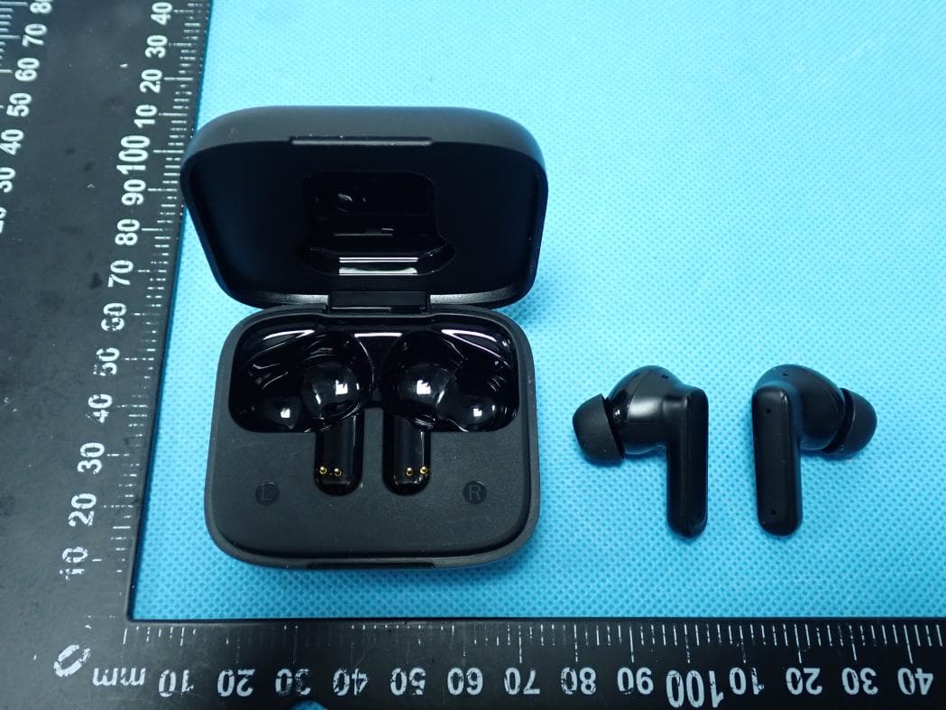
O55TWS5025
Jul 29, 2026Wireless Earbuds
Equipment Class
DSS - Part 15 Spread Spectrum Transmitter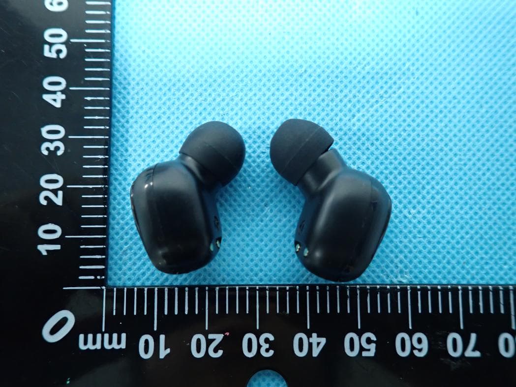
O55TWS2326
Jul 26, 2026Wireless Earbuds
Equipment Class
DSS - Part 15 Spread Spectrum Transmitter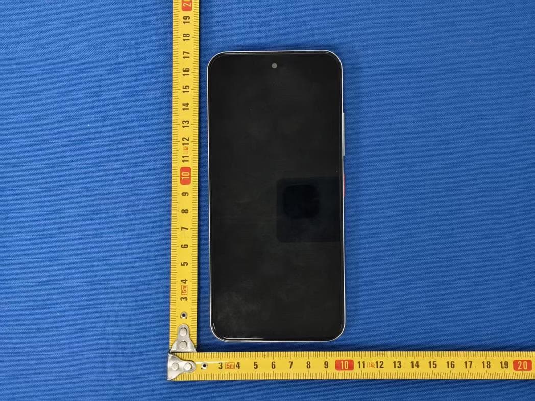
O55671626
Jul 14, 20264G MOBILE PHONE
Equipment Class
DSS - Part 15 Spread Spectrum Transmitter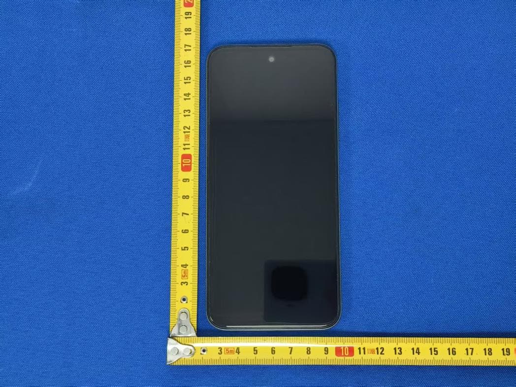
O55671526
Jul 07, 20264G MOBILE PHONE
Equipment Class
JAB - Part 15 Class B Digital Device
O55101426
Jun 23, 20264G TABLET
Equipment Class
PCB - PCS Licensed Transmitter