O55TW4819True Wireless Earphone
SWAGTEK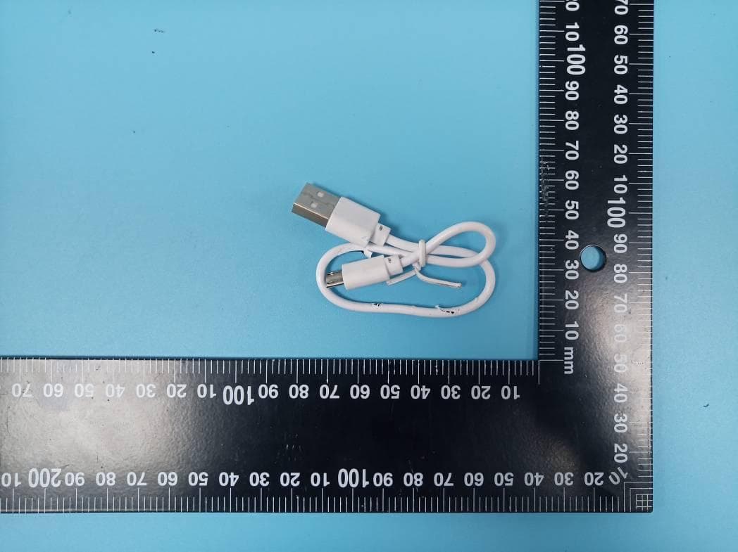
Click to zoom
Application Details
- Equipment Class
- DSS - Part 15 Spread Spectrum Transmitter
- Date of Grant
- Mar 30, 2020
- Application Purpose
- Original Equipment
- Date of Application
- Mar 30, 2020
- Equipment Note
- True Wireless Earphone
- Frequency Range
- 2402.00000000 - 2480.00000000
- Company
- SWAGTEK
- Country
- United States
Documents & Files
Document Text
Text extracted from the exhibit documents filed with the FCC. Open a document above to read the original.
Users Manual
TW3 True Wireless Earphone Manual Product Diagrammatic Package List .Earbuds (2PCS) .Charging box .USB cable .Manual .Gift box Product Specifications .Model: TW3, ZONIC, UR010 .Battery capacity: 35mAh .Charging battery: 300mAh . Power input: 5V Working time: 3 hours .Input current: 5mAh .Connection current: 3mAh .Working current: 5‐10mAh .Charging current: 260mAh Charging time: 70 minutes Transmission distance: 10 meters Products use True Wireless Connectivity (TWS) enables wireless stereo, separated left and right channels. Both the left and right ears have full Bluetooth functionality and can be used individually or in pairs. 1. Pairing Long press the touch position 5 seconds until the red and blue lights flashing alternately. Find the bluetooth name" [AL‐2] ”on cell phone bluetooth list and click it to connect. If connected successfully, the LED indicator will be off. Earbuds Pairing: The (the left and the right side) earbuds can be automaticly connected with each other after turn on. The red and blue lights flashes when earbuds are pairing with each other. The red and blue lights of the main ear flashes after paired and led of the other goes off. Using it again for the same phone: Long press the touch position 5 seconds until the red and blue lights flashing alternately, It will be automatically paired successfully. Using for another phone: Long press the touch position 5 seconds until the red and blue lights flashing alternately and find the bluetooth name" [AL‐2]" on cellphone bluetooth list and click it to connect. 2. Power Off Long press the touch position 5 seconds,the LED flashes three times, then power off. You only need to turn off one earbud, the other side will be off automatically when the earbuds paired. If the earbuds are power on status and are not connected with the mobile phone, they will automatically turn off after 5 minutes. 3. Call Support answering the call when earbuds connect with cell phone. Support binaural call. Answer or Hang UP: Short press the earbuds to answer or hang up the call. Reject the call: Long press the earbuds to reject. Interrupt the call: Short press the headset to interrupt the call. 3. Listening to Music Support listenning to music when the earbuds are on and connect with your cell phone. Pause/Play: Touch the earbud to pause or paly the music. Previous song: Double click the left side earbud to go to the previous song, Next song; Double click the right side earbud to go to the next song. Increase the volume: Click the left side earbud for three times continuously to increase the volume. Decrease the volume: Click the right side earbud for three times continuously to decrease the volume. Call Siri: Long press the earbud for three seconds to call the siri Precautions 1. The earphones should be stored in a dry and ventilated environment, to avoid oil, water; moisture and dust affecting product performance. 2. Avoid using stimulus, organic solvents or items containing these ingredients to clean the earphones. 3. The use of earphones should be correctly as per the specification, pay attention to use the influence of environment on the earphones. In order to ensure the smooth connection, it's recommended that the distance between the earphones and phones with in 10 meters. 4. If the earphones failed to connect or with poor connection, pls do not take apart the earphones or the accessories on your own. Otherwise, no warranty. 5. Regarding charging earphones. Pls use the standard usb cable or pointed charging cable from our company to charge the earphones. 6. In order to ensure normal use, please ensure sufficient power of the earphones. FCC Warning: Any Changes or modifications not expressly approved by the party responsible for compliance could void the user's authority to operate the equipment. This device complies with part 15 of the FCC Rules. Operation is subject to the following two conditions: (1) This device may not cause harmful interference, and (2) this device must accept any interference received, including interference that may cause undesired operation. Note: This equipment has been tested and found to comply with the limits for a Class B digital device, pursuant to part 15 of the FCC Rules. These limits are designed to provide reasonable protection against harmful interference in a residential installation. This equipment generates , uses and can radiate radio frequency energy and, if not installed and used in accordance with the instructions, may cause harmful interference to radio communications. However, there is no guarantee that interference will not occur in a particular installation. If this equipment does cause harmful interference to radio or television reception, which can be determined by turning the equipment off and on, the user is encouraged to try to correct the interference by one or more of the following measures: —Reorient or relocate the receiving antenna. —Increase the separation between the equipment and receiver. —Connect the equipment into an outlet on a circuit different from that to which the receiver is connected. —Consult the dealer or an experienced radio/TV technician for help. This equipment complies with FCC radiation exposure limits set forth for an uncontrolled environment. This transmitter must not be co‐located or operating in conjunction with any other antenna or transmitter. FCC ID: O55TW4819
Cover Letter(s)
QA-FR-170-B Company Name : SWAGTEK Address: 10205 NW 19 th St. Suite 101, Miami, FL, 33172 Email: [email protected] Tel: 13054219938 FCC Authorization 2019/12/16 FEDERAL COMMUNICATIONS COMMISSIONS Authorization and Evaluation Division 7435 Oakland Mills Road Columbia, MD 21046 Subject: Agent Authorization To whom it may concern: We ( SWAGTEK ), the undersigned, hereby authorize Bay Area Compliance Laboratories Corporation to act on its behalf in all matters relating to application for Equipment authorization, including the signing of all documents relating to these matters. All acts carried out by Bay Area Compliance Laboratory Corporation on our behalf shall have the same effect as our own action. We, the undersigned, hereby certify that we are not subject to a denial of federal benefits, that includes FCC benefits, pursuant to Section 5301 of the Anti-Drug Abuse Act of 1988, 21 U.S.C. 862. This authorization is valid until further written notice from the applicant. Sincerely, Signature: Charles Cheng Title: Manager
Cover Letter(s)
Company Name : SWAGTEK Address: 10205 NW 19 th St. Suite 101, Miami, FL, 33172 Email: [email protected] Tel:13054219938 FCC Confidential Authorization 2019/12/16 FEDERAL COMMUNICATIONS COMMISSIONS Authorization and Evaluation Division 7435 Oakland Mills Road Columbia, MD 21046 Subject: Confidentiality Request regarding application for certification of FCC ID: O55TW4819 In accordance with Sections 0.457 and 0.459 of the Commission’s Rules, (SWAGTEK) hereby requests long-term confidential treatment of information accompanying this application as outlined below: • Block Diagram • Schematics • Operation Description The above materials contain proprietary and confidential information not customarily released to the public. The public disclosure of these materials provides unjustified benefits to its competitors in the market. Sincerely, Signature: Charles Cheng Title: Manager
Cover Letter(s)
Company Name : SWAGTEK Address: 10205 NW 19th St. Suite 101, Miami, FL, 33172 Email: [email protected] Tel: 13054219938 Product Similarity Declaration Date: 2019-12-16 To: Bay Area Compliance Laboratories Corp. 1274 Anvilwood Avenue Sunnyvale, CA 94089 Dear Sir/Madam, We, SWAGTEK, hereby declare that we have a product named as True Wireless Earphone, (model: TW3, FCC ID: O55TW4819) was tested by BACL, Meanwhile, for our marketing purpose, we would like to list a series model (ZONIC, UR010) on reports and certificate, all the models are identical in schematics & trade name, they have different model name and appearance. No other changes are made on them. We confirm that all information above is true, and we’ll be responsible for all the consequences. Please contact me if you have any question. Sincerely, Signature: Charles Cheng Manager
Cover Letter(s)
Company Name: SWAGTEK Address: 10205 NW 19th St. Suite 101, Miami, FL, 33172 Email: [email protected] Tel: 13054219938 Date: 2019-12-16 FEDERAL COMMUNICATIONS COMMISSIONS Authorization and Evaluation Division 7435 Oakland Mills Road Columbia, MD 21046 To whom it may concern: We, SWAGTEK, hereby declare that we have a product named as True Wireless Earphone, (FCC ID: O55TW4819, Model: TW3, ZONIC, UR010) was tested by BACL, which has left earphone and right earphone. We would like to declare that the left and right earphones are identical in the Antenna & RF circuits. The RF chip, model AB5357A supports BDR (GFSK), EDR (π/4-DQPSK, 8DPSK), and BLE functions. For use in America and this chip will not support/enable BLE function. The BLE function has been shielded by the manufacturer using the software. We confirm that all information above is true, and we’ll be responsible for all the consequences. Please contact me if you have any question. Sincerely, Signature: Charles Cheng Title: Manager
Cover Letter(s)
Company Name: SWAGTEK Address: 10205 NW 19th St. Suite 101, Miami, FL, 33172 Email: [email protected] Tel: 3054219938 FCC ID Cover Letter The SWAGTEK here by submits justification for placing the FCC ID in the Associated User Manual. According to the FCC Regulation and Guidance (KDB Publication 784748 D01 v09r01) allows for the FCC ID to be moved to the User’s manual if the device is unquestionably too small for the FCC ID to be printed. Referring to the above quote, as the device is too small for the FCC ID: O55TW4819 to be printed. The FCC ID will be moved to the last page of user’s manual and charging case. The details are as below: A. Side surface (A): The curvature shape of the silicone sleeve back cover is not flat, so it’s hard to affix the label on the surface of the earbuds. B. Top cover (B): The plastic of the top cover does not provide enough physical space to fit the printing of the FCC ID according to below reference picture. Conclusion: Based on the above description of area A to B, we conclude that the device is unquestionably too small for enabling the FCC ID to be printed onto any surface. We therefore request to move the FCC ID to the User manual and charging case. Best regards, Sincerely, Signature: Charles Cheng Title: Manager
External Photos
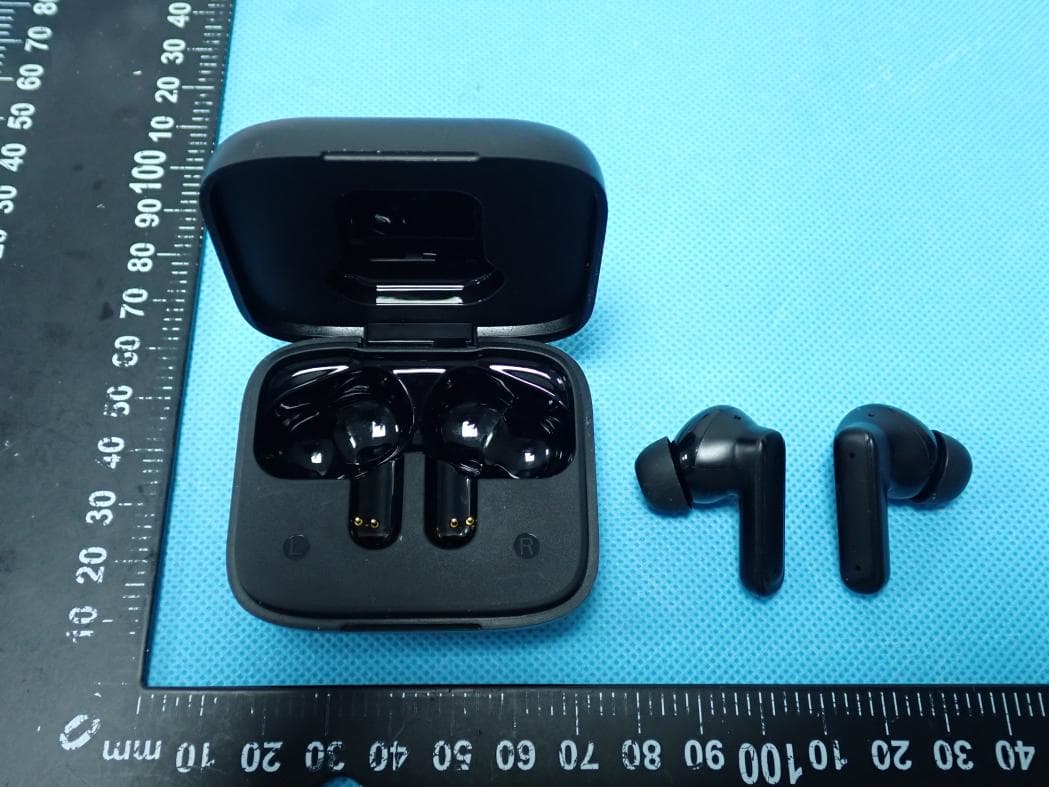
EXHIBIT B - EUT EXTERNAL PHOTOGRAPHS Charging Case Left Earbud Right Earbud
ID Label/Location Info
EXHIBIT A - FCC ID LABEL AND LOCATION FCC ID Label FCC ID Label Location Information The label shown shall be permanently affixed at a conspicuous location on the device and be readily visible to the user at the time purchase (Labeling requirements per 2.925)
Internal Photos
EXHIBIT C - EUT INTERNAL PHOTOGRAPHS Charging Case Left Earbud Antenna Right Earbud Antenna
Test Report
Note: This report must not be used by the customer to claim product certification, approval, or endorsement by A2LA* or any agency of the Federal Government. This report may contain data that are not covered by the A2LA accreditation and are marked with an asterisk “★”. BACL is not responsible for the authenticity of any test data provided by the applicant. Data included from the applicant that may affect test results are marked with an asterisk ’*’. Customer model name, addresses, names, trademarks etc. are not considered data. This report cannot be reproduced except in full, without prior written approval of the Company. Unless otherwise stated the results shown in this test report refer only to the sample(s) tested. This report is valid only with a valid digital signature. The digital signature may be available only under the Adobe software above version 7.0. FCC PART 15.247 TEST REPORT For SWAGTEK 10205 NW 19th Street STE101 Miami Florida 33172 United States FCC ID: O55TW4819 R e p o r t T y p e : O r i gi n a l R e p o r t P r o d u c t T y p e: T r u e W i r e l e s s E a r p h o n e Report Number: RSZ191216004-00A Report Date: 2020-01-02 Reviewed By: Kieron Luo RF Engineer Prepared By: Bay Area Compliance Laboratories Corp. (Shenzhen) 6/F., West Wing, Third Phase of Wanli Industrial Building, Shihua Road, Futian Free Trade Zone, Shenzhen, Guangdong, China Tel: +86-755-33320018 Fax: +86-755-33320008 www.baclcorp.com.cn Bay Area Compliance Laboratories Corp. (Shenzhen) Report No.: RSZ191216004-00A FCC Part 15.247 Page 2 of 30 TABLE OF CONTENTS GENERAL INFORMATION ....................................................................................................................................... 4 PRODUCT DESCRIPTION FOR EQUIPMENT UNDER TEST (EUT) ..................................................................................... 4 OBJECTIVE ................................................................................................................................................................... 4 RELATED SUBMITTAL(S)/GRANT(S) ............................................................................................................................. 4 TEST METHODOLOGY .................................................................................................................................................. 4 MEASUREMENT UNCERTAINTY .................................................................................................................................... 5 TEST FACILITY ............................................................................................................................................................. 5 SYSTEM TEST CONFIGURATION .......................................................................................................................... 6 DESCRIPTION OF TEST CONFIGURATION ...................................................................................................................... 6 EUT EXERCISE SOFTWARE .......................................................................................................................................... 6 SPECIAL ACCESSORIES ................................................................................................................................................. 6 EQUIPMENT MODIFICATIONS ....................................................................................................................................... 6 SUPPORT EQUIPMENT LIST AND DETAILS .................................................................................................................... 6 EXTERNAL I/O CABLE.................................................................................................................................................. 6 BLOCK DIAGRAM OF TEST SETUP ................................................................................................................................ 7 SUMMARY OF TEST RESULTS ............................................................................................................................... 8 TEST EQUIPMENT LIST ........................................................................................................................................... 9 FCC§15.247 (i), §1.1307 (b) (1) &§2.1093 – RF EXPOSURE ...................................................................................... 10 APPLICABLE STANDARD ............................................................................................................................................ 10 FCC §15.203 – ANTENNA REQUIREMENT .......................................................................................................... 11 APPLICABLE STANDARD ............................................................................................................................................ 11 ANTENNA CONNECTOR CONSTRUCTION .................................................................................................................... 11 FCC §15.207 (a) – AC LINE CONDUCTED EMISSIONS ..................................................................................... 12 APPLICABLE STANDARD ............................................................................................................................................ 12 EUT SETUP ................................................................................................................................................................ 12 EMI TEST RECEIVER SETUP ....................................................................................................................................... 12 TEST PROCEDURE ...................................................................................................................................................... 12 CORRECTED FACTOR & MARGIN CALCULATION .........................................................................................…
Text truncated - open the document above for the full version.
Test Report
Item A: 20dB Emission Bandwidth Test Result TestMode Antenna Channel 20db EBW[MHz] Limit[MHz] Verdict DH1 Ant1 2402 0.909 --- PASS 2441 0.909 --- PASS 2480 0.915 --- PASS 2DH1 Ant1 2402 1.245 --- PASS 2441 1.248 --- PASS 2480 1.251 --- PASS 3DH1 Ant1 2402 1.212 --- PASS 2441 1.215 --- PASS 2480 1.215 --- PASS Test Graphs DH1_Ant1_2402 DH1_Ant1_2441 DH1_Ant1_2480 2DH1_Ant1_2402 2DH1_Ant1_2441 2DH1_Ant1_2480 3DH1_Ant1_2402 3DH1_Ant1_2441 3DH1_Ant1_2480 Item B: Maximum conducted output power Test Result TestMode Antenna Channel Result[dBm] Limit[dBm] Verdict DH1 Ant1 2402 3.86 <=20.97 PASS 2441 2.33 <=20.97 PASS 2480 1.63 <=20.97 PASS 2DH1 Ant1 2402 4.57 <=20.97 PASS 2441 3.05 <=20.97 PASS 2480 2.35 <=20.97 PASS 3DH1 Ant1 2402 5.39 <=20.97 PASS 2441 3.76 <=20.97 PASS 2480 3.08 <=20.97 PASS Test Graphs DH1_Ant1_2402 DH1_Ant1_2441 DH1_Ant1_2480 2DH1_Ant1_2402 2DH1_Ant1_2441 2DH1_Ant1_2480 3DH1_Ant1_2402 3DH1_Ant1_2441 3DH1_Ant1_2480 Item C: Carrier frequency separation Test Result TestMode Antenna Channel Result[MHz] Limit[MHz] Verdict DH1 Ant1 Hop 1 >=0.606 PASS 2DH1 Ant1 Hop 1 >=0.832 PASS 3DH1 Ant1 Hop 1.003 >=0.810 PASS Test Graphs DH1_Ant1_Hop 2DH1_Ant1_Hop 3DH1_Ant1_Hop Item D: Time of occupancy Test Result TestMode Antenna Channel BurstWidth [ms] TotalHops [Num] Result[s] Limit[s] Verdict DH1 Ant1 Hop 0.39 330 0.13 <=0.4 PASS DH3 Ant1 Hop 1.64 160 0.263 <=0.4 PASS DH5 Ant1 Hop 2.88 110 0.317 <=0.4 PASS 2DH1 Ant1 Hop 0.40 330 0.133 <=0.4 PASS 2DH3 Ant1 Hop 1.65 180 0.296 <=0.4 PASS 2DH5 Ant1 Hop 2.89 120 0.347 <=0.4 PASS 3DH1 Ant1 Hop 0.40 320 0.129 <=0.4 PASS 3DH3 Ant1 Hop 1.65 190 0.313 <=0.4 PASS 3DH5 Ant1 Hop 2.89 120 0.347 <=0.4 PASS Note 1:A period time=0.4*79=31.6(S), Total of Dwell=Pluse T ime*Hopping Number Note 2: Hopping Number=Hopping Number in 3.16s*10 Note 3: Hoping Number in 3.16s=Total of highest signals in 3.16s(Secong high signals were other channel) Test Graphs DH1_Ant1_Hop DH3_Ant1_Hop DH5_Ant1_Hop 2DH1_Ant1_Hop 2DH3_Ant1_Hop 2DH5_Ant1_Hop 3DH1_Ant1_Hop 3DH3_Ant1_Hop 3DH5_Ant1_Hop Item E: Number of hopping channels Test Result TestMode Antenna Channel Result[Num] Limit[Num] Verdict DH1 Ant1 Hop 79 >=15 PASS 2DH1 Ant1 Hop 79 >=15 PASS 3DH1 Ant1 Hop 79 >=15 PASS Test Graphs DH1_Ant1_Hop 2DH1_Ant1_Hop 3DH1_Ant1_Hop Item F:Band edge measurements Test Graphs DH1_Ant1_Low_2402 DH1_Ant1_High_2480 DH1_Ant1_Low_Hop_2402 DH1_Ant1_High_Hop_2480 2DH1_Ant1_Low_2402 2DH1_Ant1_High_2480 2DH1_Ant1_Low_Hop_2402 2DH1_Ant1_High_Hop_2480 3DH1_Ant1_Low_2402 3DH1_Ant1_High_2480 3DH1_Ant1_Low_Hop_2402 3DH1_Ant1_High_Hop_2480
Test Setup Photos
EXHIBIT D - TEST SETUP PHOTOGRAPHS Conducted Emissions - Front View Conducted Emissions - Side View Radiated Emissions View (Below 1 GHz) Radiated Emissions View (Above 1 GHz)
Contact Information
Applicant
Charles Cheng(Manager)
Test Firm
Bay Area Compliance Laboratories Corp. (Shenzhen)Well Wang
[email protected]+86 (0) 755 33320018
Technical Specifications
| # | Rule Parts | Frequency Range | Power Output |
|---|---|---|---|
| 1 | 15C | 2.40 GHz - 2.48 GHz | 3.00 mW |
Other Applications from SWAGTEK
O55TWS5025
Jul 29, 2026Wireless Earbuds
Equipment Class
DSS - Part 15 Spread Spectrum Transmitter
O55TWS2326
Jul 26, 2026Wireless Earbuds
Equipment Class
DSS - Part 15 Spread Spectrum Transmitter
O55671626
Jul 14, 20264G MOBILE PHONE
Equipment Class
DSS - Part 15 Spread Spectrum Transmitter
O55671526
Jul 07, 20264G MOBILE PHONE
Equipment Class
JAB - Part 15 Class B Digital Device
O55101426
Jun 23, 20264G TABLET
Equipment Class
PCB - PCS Licensed Transmitter