O63GH5850HDLD03Digital Cordless Phone � Handset Unit
Lionda Technology Co Ltd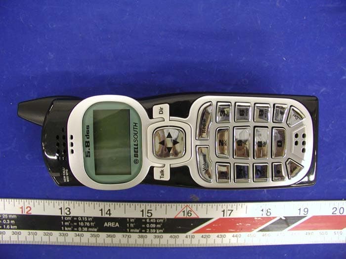
Click to zoom
Application Details
- Equipment Class
- DTS - Digital Transmission System
- Date of Grant
- May 23, 2004
- Application Purpose
- Original Equipment
- Date of Application
- Dec 10, 2003
- Equipment Note
- Digital Cordless Phone � Handset Unit
- Frequency Range
- 5729.28000000 - 5808.12800000
- Company
- Lionda Technology Co Ltd
- Country
- China
Documents & Files
Document Text
Text extracted from the exhibit documents filed with the FCC. Open a document above to read the original.
Users Manual
Multi-HANDSET, Multi-BASE UNIT 5.8GHz Digital Spread Spectrum Technology CORDLESS ALL DIGITAL ANSWERING SYSTEM WITH CALLER ID/CALL WAITING 156 CHANNEL AUTOHOP Model GH5860 OWNER’S MANUAL INSTALLATION AND OPERATING INSTRUCTIONS PLEASE READ THIS MANUAL CAREFULLY BEFORE USE. KEEP FOR YOUR REFERENCE. For installation information, please see “Getting Started” instructions on page 6 or your separate Quick Start guide. vol+ play s k i p r p t m e m o code P a g e I n U s e / C h g A n s O n / O f f S p k erase stop vol- time ogm m 1 m2 m3 m 4 S p k A n s O n / O f f 1 9 # 0 wx yz 5.8 dss TALK ME NU RE/PA E D I T D E L VOLSAVE F L A S H C H A N DIR/ ES C 2 ab c 3 de f 6 mn o 5 jkl 4 gh i 7 pq rs 8 tuv 5860 man.qxd 11/7/2003 5:47 PM Page 1 Special Features Special Fea ongratulations on your selection of a quality BellSouth Product. With proper care and adherence to the set-up and user instructions in this Owner's Manual, this unit will provide you with years of trouble-free service. Tevionis committed to providing quality products that fit your needs. We would like to have any comments or suggestions you might have on this product. You may mail your comments to: U.S. Electronics 105 Madison Avenue New York, NY 10016 When examining your new Tevion cordless telephone, you will find an array of special features including: Digital Spread Spectrum Technology - Utilizes a “wider frequency band” for a more secure conversation with a clarity of digital sound, extended range, and minimal interference from other cordless telephones. 156 Channel Auto-hop- When interference is received, the telephone automatically hops to the clearest channel. Desk or Wall Mount- Use this equipment as a desk phone or as a wall phone. Tone or Pulse Dialing- Use this phone for either TONE (push-button) or PULSE (rotary) dialing. Automated Functions - Redial the last number called and automatic STANDBY mode. Security- Ensures greater privacy because of a built-in security code with 4,000,000 possible combinations that prevents use of your telephone line by another nearby cordless phone. Special Services- Use the button to access special services such as Call Waiting supplied by your telephone company or company switchboard. STANDBY Mode- When in STANDBY mode (ON-HOOK), the phone is capable of receiving a call. When the HANDSETis on the BASE UNIT, it is automatically in the STANDBY mode (ON- HOOK). When the HANDSETis taken off the BASE UNIT, it remains in the STANDBY mode until you activate the button. Battery Power Saver- Recharge your BATTERY PACK many times with the built-in CHARGER. Once fully charged, in STANDBY mode, the HANDSET can receive/send calls for a maximum of ten days without the need for recharging. Length of charge depends on frequency of use. Luminous LCD Screen- The LCD Screen emits light for 5 seconds every time you press any of the TELEPHONE KEYPAD buttons. HANDSET Ringer Level- Select the ringer sound level (High, Low, Off). HANDSET Ring Melody- Select the desired ring melody from the 10 available melodies. HANDSET Volume Control- Press the /MENU button and then select the desired receiver volume setting from Low, Medium, High, or Maximum. Alarm Clock- The telephone emits a distinctive sound when the ALARM CLOCK function is activated (See page 27). HEADSET JACK- Your telephone can utilize a headset for hands-free communication. BELT CLIP- Use the BELT CLIP to hang your HANDSET on your belt. C TALK EDIT VOL 5860 man.qxd 11/7/2003 5:48 PM Page 2 Special Features CALLER ID SYSTEM Multi-Function Large LCD Screen- Shows the number you are dialing and, with Caller ID service available through subscription from your local telephone company, displays information about the caller before you answer the call. Name and Number DIRECTORY (PHONE BOOK) - Stores up to 40 names and numbers so that you can call them with a single key stroke. Caller List- Available with Caller ID service. Stores up to 50 calls to keep track of everyone who called. The name, phone number, time and date of the call are recorded. Allows you to return their calls with a few key strokes. Outgoing Call Memory- The telephone stores the last 8 OUTGOING CALLS to keep track of everyone you called. The phone number, time, date, and the duration of the call are recorded. Allows you to call them again with a single key stroke. Preferred Calls - You can mark the name and number of a welcome caller in the DIRECTORY (PHONE BOOK). When that number calls in, the caller’s name will appear on the LCD Screen and a special ring will sound or a selected PREFERRED RING MELODY will be heard. Blocked Calls - You can mark the name and number of an unwelcome caller in the DIRECTORY (PHONE BOOK). When that number calls in, the caller’s name will appear on the LCD Screen and the ringer will be disabled. Repeat Call Indicator- Shows if a new incoming call has called more than once. Out of Area Call Indicator- Advises you that the incoming call is not in a Caller ID service area. Unavailable Call Indicator- Advises you that the origin of the incoming call does not support the Caller ID system. Call Waiting Service- Displays the name and number of the second caller, if you have subscribed to Call Waiting service from your local telephone company (see page 14.) MULTI-HANDSET, MULTI-BASE UNIT SYSTEM Multi-HANDSET- Registers a total of 9 HANDSETSinto the operating system. Multi-BASE UNIT - The user can have the option to add another BASE UNIT. The system supports 2 BASE UNITSconnected to separate telephone lines. Once registered, the HANDSETScan link to either of the BASE UNITSto make and/or receive a call. Automatic Linking - All 9 HANDSETS can register to the twoBASE UNITS (B1, B2). When the FIRST BASE UNIT (B1)is already engaged, the other HANDSETScan automatically link to the SECOND BASE UNIT (B2)by pressing the button. Intercom Call- A HANDSETcan make an INTERCOM call to the other HANDSETS in the system. Call Transfer- During a telephone conversation, the call can be transf…
Text truncated - open the document above for the full version.
Cover Letter(s)
Response to: FCC ID O63GH5850HDLD03 Applicant: Lionda Technology Co Ltd Correspondence Reference Number: 26338 731 Confirmation Number: EA194383 1) Please provide probe calibration information. The probe was calibrated from 150 MHz to 5800 MHz. (See updated SAR report page 8-17). There was an inadvertent omission of the 5.2 and 5.8 calibration data. The probe used is rated to 6 GHz and its model is ES3DV2. 2) Please justify verification target value. There is a typo that has been corrected on page 40, the 900 MHz should be 5800 MHz instead. It was verified by performing 10 scans with head liquid and 10 scans with body liquid. We then used the average value for target values. (see files “additional body system validation” & “additional head system validation”) 3) Please confirm that the belt clip was used not for testing. Please state whether the belt clip mentioned in the user manual contains metallic components. If so please provide SAR results with the clip. Testing was performed with belt clip. See upper photo on page 51. FYI Please be advised SAR test results for 5 GHz devices are typically not request at conducted and radiated average powers under 50 mW for FCC filings. Tissue parameters appear to be more than 10% from target. Please improve in the future. Speag suggests there are issues with the standard probe at 5 GHz. They are offering a new probe for 5 GHz work. Please check with them. We recently purchased and received the ES3DV2 6 GHz probe from SPEAG.
Cover Letter(s)
Block 2 Laodong 2nd Industria Area, Xixian, Baoan, Shenzhen, China Tel.: 86-755-7917824/ 86-755-7902415, Fax: 86-755-7917944 Federal Communications Commission Authorization and Evaluation Division Confidentiality Request regarding application for certification of model GH5860: FCC ID: O63GH5860BDLD03 (Base) FCC ID: O63GH5850HDLD03 (Handset) Pursuant to Sections 0.457 and 0.459 of the Commission’s Rules, we hereby request confidential treatment of information accompanying this application as outlined below: • Schematics • Block Diagram • Circuit Description The above documents contain information for new 5.8GHz / 2.4 GHz DSS (Cordless Telephone) technology and ideas, so we would like to prevent the use of this information by other companies. The applicant understands that pursuant to Section 0.457 of the Rules, disclosure of this application and all accompanying documentation will not be made before the date of the Grant for this application. Sincerely, Dan Coronia – Senior Engineer
External Photos
Lionda Technology Company Limited FCC ID: O63GH5850HDLD03 APPENDIX C - EUT PHOTOGRAPHS Handset - Top View Handset - Back View
ID Label/Location Info
APPENDIX A - FCC PRODUCT LABELING AND WARNING STATEMENT FCC ID Label Specifications: Text is black or white in color and is left justified. Labels are silk-screened and shall be “permanently affixed” at a conspicuous location on the EUT. Proposed Label Location on EUT Back Side of Handset/Proposed FCC ID FCC ID: O63GH5850HDLD03 This device complies with Part 15 of the FCC Rules. Operation is subject to the following two conditions: (1) this device may not cause harmful interference, and (2) this device must accept any interference received, including interference that may cause undesired operation. Privacy of communications may not be ensured when using this phone.
Internal Photos
Lionda Technology Company Limited FCC ID: O63GH5850HDLD03 Handset – Board and Housing View Handset - Main Board Component View Lionda Technology Company Limited FCC ID: O63GH5850HDLD03 Handset - Main Board Solder View Handset - Transceiver Top Side View Lionda Technology Company Limited FCC ID: O63GH5850HDLD03 Handset - Transceiver Bottom View Handset - Transceiver Cover Removed Component View Lionda Technology Company Limited FCC ID: O63GH5850HDLD03 Handset - Transceiver Cover Removed Solder View
Operational Description
LIONDA TECHNOLOGY COMPANY LIMITED Lionda Research and Development Center GH5860freq.doc 1 08/04/03 GH5860 DSS FREQUENCY CHART CH TX (BS&HS RF 5.8GHz) TX (BS&HS RF 2.4GHz) CH TX (BS&HS RF 5.8GHz) TX (BS&HS) RF 2.4GHz) 1 5729.280 2402.304 40 5769.216 2442.240 2 5730.304 2403.328 41 5770.240 2443.264 3 5731.328 2404.358 42 5771.264 2444.288 4 5732.352 2405.376 43 5772.288 2445.312 5 5733.376 2406.400 44 5773.312 2446.336 6 5734.400 2407.424 45 5774.336 2447.360 7 5735.424 2408.448 46 5775.360 2448.384 8 5736.448 2409.472 47 5776.384 2449.408 9 5737.472 2410.496 48 5777.408 2450.432 10 5738.496 2411.520 49 5778.432 2451.456 11 5739.520 2412.544 50 5779.456 2452.480 12 5740.544 2413.568 51 5780.480 2453.504 13 5741.568 2414.592 52 5781.504 2454.528 14 5742.592 2415.616 53 5782.528 2455.552 15 5743.616 2416.640 54 5783.552 2456.576 16 5744.640 2417.664 55 5784.576 2457.600 17 5745.664 2418.688 56 5785.600 2458.624 18 5746.688 2419.712 57 5786.624 2459.648 19 5747.712 2420.736 58 5787.648 2460.672 20 5748.736 2421.760 59 5788.672 2461.696 21 5749.760 2422.784 60 5789.696 2462.720 22 5750.784 2423.808 61 5790.720 2463.744 23 5751.808 2424.832 62 5791.744 2464.768 24 5752.832 2425.856 63 5792.768 2465.792 25 5753.856 2426.880 64 5793.792 2466.816 26 5754.880 2427.904 65 5794.816 2467.840 27 5755.904 2428.928 66 5795.840 2468.864 28 5756.928 2429.952 67 5796.864 2469.888 29 5757.952 2430.976 68 5797.888 2470.912 30 5758.976 2432.000 69 5798.912 2471.936 31 5760.000 2433.024 70 5799.936 2472.960 32 5761.024 2434.048 71 5800.960 2473.984 33 5762.048 2435.072 72 5801.984 2475.008 34 5763.072 2436.096 73 5803.008 2476.032 35 5764.096 2437.120 74 5804.032 2477.056 36 5765.120 2438.144 75 5805.056 2478.080 37 5766.144 2439.168 76 5806.080 2479.104 38 5767.168 2440.192 77 5807.104 2480.128 39 5768.192 2441.216 78 5808.128 2481.152 NOTE: Local Frequency is: 3326.976MHz
RF Exposure Info
Note: This test report is specially limited to the above client company and the product model only. It may not be duplicated without prior written consent of Bay Area Compliance Laboratory Corporation. This report must not be used by the client to claim product endorsement by NVLAP or any agency of the U.S. Government. SAR EVALUATION REPORT For LIONDA TECHNOLOGY COMPANY LIMITED Block 2 Laodong 2 nd Industrial Area, Xixian, Baoan, Shenzhen, Guangdong, China 518102 FCC ID: O63GH5850HDLD03 2003-11-26 This Report Concerns: Original Report Equipment Type: 2.4GHz and 5.8GHz Cordless Phone – H/S Unit Test Engineer: Eric Hong Report No.: R0308046S Test Date: 2003-11-14 Reviewed By: Ling Zhang Prepared By: Bay Area Compliance Laboratory Corporation 230 Commercial Street Sunnyvale, CA 94085 Tel: (408) 732-9162 Fax: (408) 732 9164 LIONDA TECHNOLOGY COMPANY LIMITED FCC ID: O63GH5850HDLD03 Report #R0308046S SAR Evaluation Report Page 2 of 49 TABLE OF CONTENTS SUMMARY....................................................................................................................................................................3 1 - REFERENCE ...........................................................................................................................................................5 2 - TESTING EQUIPMENT.........................................................................................................................................6 2.1 EQUIPMENT LIST & CALIBRATION INFO................................................................................................................6 2.2 EQUIPMENT CALIBRATION CERTIFICATE...............................................................................................................6 3 - EUT DESCRIPTION .............................................................................................................................................17 4 - SYSTEM TEST CONFIGURATION...................................................................................................................18 4.1 JUSTIFICATION.....................................................................................................................................................18 4.2 EUT EXERCISE PROCEDURE................................................................................................................................18 4.3 SPECIAL ACCESSORIES.........................................................................................................................................18 4.4 EQUIPMENT MODIFICATIONS...............................................................................................................................18 5 - CONDUCTED OUTPUT POWER MEASUREMENT......................................................................................19 5.1 MEASUREMENT PROCEDURE................................................................................................................................19 5.2 TEST RESULTS.....................................................................................................................................................19 6 - DOSIMETRIC ASSESSMENT SETUP...............................................................................................................21 6.1 MEASUREMENT SYSTEM DIAGRAM.....................................................................................................................22 6.2 SYSTEM COMPONENTS.........................................................................................................................................23 6.3 MEASUREMENT UNCERTAINTY............................................................................................................................27 7 - SYSTEM EVALUATION .....................................................................................................................................28 7.1 SIMULATED TISSUE LIQUID PARAMETER CONFIRMATION...................................................................................28 7.2 EVALUATION PROCEDURES..................................................................................................................................28 7.3 SYSTEM ACCURACY VERIFICATION.....................................................................................................................29 7.4 SAR EVALUATION PROCEDURE...........................................................................................................................33 7.5 EXPOSURE LIMITS................................................................................................................................................34 8 - TEST RESULTS ....................................................................................................................................................35 8.1 SAR TEST DATA..................................................................................................................................................35 8.2 PLOTS OF TEST RESULT.......................................................................................................................................35 EXHIBIT A - SAR SETUP PHOTOGRAPHS .........................................................................................................41 BACK IN TOUCH WITH PHANTOM...............................................................................................................................41 RIGHT HEAD CHEEK IN TOUCH WITH PHANTOM........................................................................................................41 RIGHT HEAD TILT IN TOUCH WITH PHANTOM............................................................................................................42 LEFT HEAD CHEEK IN TOUCH WITH PHANTOM..........................................................................................................42 LEFT HEAD TILT IN TOUCH WITH PHANTOM.......................…
Text truncated - open the document above for the full version.
RF Exposure Info
Note: This test report is specially limited to the above client company and the product model only. It may not be duplicated without prior written consent of Bay Area Compliance Laboratory Corporation. This report must not be used by the client to claim product endorsement by NVLAP or any agency of the U.S. Government. SAR EVALUATION REPORT For LIONDA TECHNOLOGY COMPANY LIMITED Block 2 Laodong 2 nd Industrial Area, Xixian, Baoan, Shenzhen, Guangdong, China 518102 FCC ID: O63GH5850HDLD03 2003-11-26 This Report Concerns: Original Report Equipment Type: 2.4GHz and 5.8GHz Cordless Phone – H/S Unit Test Engineer: Eric Hong Report No.: R0308046S Test Date: 2003-11-14 Reviewed By: Ling Zhang Prepared By: Bay Area Compliance Laboratory Corporation 230 Commercial Street Sunnyvale, CA 94085 Tel: (408) 732-9162 Fax: (408) 732 9164 LIONDA TECHNOLOGY COMPANY LIMITED FCC ID: O63GH5850HDLD03 Report #R0308046S_REV SAR Evaluation Report Page2of 59 TABLE OF CONTENTS SUMMARY....................................................................................................................................................................3 1 - REFERENCE ...........................................................................................................................................................5 2 - TESTING EQUIPMENT.........................................................................................................................................6 2.1 EQUIPMENT LIST & CALIBRATION INFO................................................................................................................6 2.2 EQUIPMENT CALIBRATION CERTIFICATE...............................................................................................................6 3 - EUT DESCRIPTION .............................................................................................................................................27 4 - SYSTEM TEST CONFIGURATION...................................................................................................................28 4.1 JUSTIFICATION.....................................................................................................................................................28 4.2 EUT EXERCISE PROCEDURE................................................................................................................................28 4.3 SPECIAL ACCESSORIES.........................................................................................................................................28 4.4 EQUIPMENT MODIFICATIONS...............................................................................................................................28 5 - CONDUCTED OUTPUT POWER MEASUREMENT......................................................................................29 5.1 MEASUREMENT PROCEDURE................................................................................................................................29 5.2 TEST RESULTS.....................................................................................................................................................29 6 - DOSIMETRIC ASSESSMENT SETUP...............................................................................................................31 6.1 MEASUREMENT SYSTEM DIAGRAM.....................................................................................................................32 6.2 SYSTEM COMPONENTS.........................................................................................................................................33 6.3 MEASUREMENT UNCERTAINTY............................................................................................................................37 7 - SYSTEM EVALUATION .....................................................................................................................................38 7.1 SIMULATED TISSUE LIQUID PARAMETER CONFIRMATION...................................................................................38 7.2 EVALUATION PROCEDURES..................................................................................................................................38 7.3 SYSTEM ACCURACY VERIFICATION.....................................................................................................................39 7.4 SAR EVALUATION PROCEDURE...........................................................................................................................43 7.5 EXPOSURE LIMITS................................................................................................................................................44 8 - TEST RESULTS ....................................................................................................................................................45 8.1 SAR TEST DATA..................................................................................................................................................45 8.2 PLOTS OF TEST RESULT.......................................................................................................................................45 EXHIBIT A - SAR SETUP PHOTOGRAPHS .........................................................................................................51 BACK IN TOUCH WITH PHANTOM...............................................................................................................................51 RIGHT HEAD CHEEK IN TOUCH WITH PHANTOM........................................................................................................51 RIGHT HEAD TILT IN TOUCH WITH PHANTOM............................................................................................................52 LEFT HEAD CHEEK IN TOUCH WITH PHANTOM..........................................................................................................52 LEFT HEAD TILT IN TOUCH WITH PHANTOM.....................…
Text truncated - open the document above for the full version.
RF Exposure Info
LIONDA TECHNOLOGY COMPANY LIMITED FCC ID: O63GH5850HDLD03 Report #R0308046S_REV SAR Evaluation Report Page31of 59 6 - DOSIMETRIC ASSESSMENT SETUP These measurements were performed with the automated near-field scanning system DASY3 from Schmid & Partner Engineering AG (SPEAG). The system is based on a high precision robot (working range greater than 0.9m) which positions the probes with a positional repeatability of better than ±0.02mm. Special E- and H-field probes have been developed for measurements close to material discontinuity, the sensors of which are directly loaded with a Schottky diode and connected via highly resistive lines to the data acquisition unit. The system is described in detail in [3]. The SAR measurements were conducted with the dosimetric probe ET3DV2 SN: 3019 (manufactured by SPEAG), designed in the classical triangular configuration [3] and optimized for dosimetric evaluation. The probe has been calibrated according to the procedure described in [7] with accuracy of better than ±10%. The spherical isotropy was evaluated with the procedure described in [8] and found to be better than ±0.25dB. The phantom used was the \Generic Twin Phantom” described in [4]. The ear was simulated as a spacer of 4 mm thickness between the earpiece of the phone and the tissue simulating liquid. The Tissue simulation liquid used for each test is in according with the FCC OET65 supplement C as listed below. Target Frequency Head Body (MHz) ε r σ (S/m) ε r σ (S/m) 150 52.3 0.76 61.9 0.80 300 45.3 0.87 58.2 0.92 450 43.5 0.87 56.7 0.94 835 41.5 0.90 55.2 0.97 900 41.5 0.97 55.0 1.05 915 41.5 0.98 55.0 1.06 1450 40.5 1.20 54.0 1.30 1610 40.3 1.29 53.8 1.40 1800 – 2000 40.0 1.40 53.3 1.52 2450 39.2 1.80 52.7 1.95 3000 38.5 2.40 52.0 2.73 5800 35.3 5.27 48.2 6.00 LIONDA TECHNOLOGY COMPANY LIMITED FCC ID: O63GH5850HDLD03 Report #R0308046S_REV SAR Evaluation Report Page32of 59 6.1 Measurement System Diagram The DASY3 system for performing compliance tests consist of the following items: 1. A standard high precision 6-axis robot (Stäubli RX family) with controller and software. 2. An arm extension for accommodating the data acquisition electronics (DAE). 3. A dosimetric probe, i.e., an isotropic E-field probe optimized and calibrated for usage in tissue simulating liquid. The probe is equipped with an optical surface detector system. 4. A data acquisition electronic (DAE), which performs the signal amplification, signal multiplexing, AD-conversion, offset measurements, mechanical surface detection, collision detection, etc. The unit is battery powered with standard or rechargeable batteries. The signal is optically transmitted to the EOC. 5. A unit to operate the optical surface detector, which is connected to the EOC. The Electro-optical coupler (EOC) performs the conversion from the optical into a digital electric signal of the DAE. The EOC is connected to the PC plug-in card. The functions of the PC plug-in card based on a DSP is to perform the time critical task such as signal filtering, surveillance of the robot operation fast movement interrupts. 6. A computer operating Windows 95 or larger 7. DASY3 software 8. Remote control with teaches pendant and additional circuitry for robot safety such as warning lamps, etc. 9. The generic twin phantom enabling testing left-hand and right-hand usage. 10. The device holder for handheld EUT. 11. Tissue simulating liquid mixed according to the given recipes (see Application Note). 12. System validation dipoles to validate the proper functioning of the system. LIONDA TECHNOLOGY COMPANY LIMITED FCC ID: O63GH5850HDLD03 Report #R0308046S_REV SAR Evaluation Report Page33of 59 6.2 System Components ET3DV6 Probe Specification Construction Symmetrical design with triangular core Built-in optical fiber for surface detection System Built-in shielding against static charges Calibration In air from 10 MHz to 2.5 GHz In brain and muscle simulating tissue at Frequencies of 450 MHz, 900 MHz and 1.8 GHz (accuracy ± 8%) Frequency 10 MHz to > 6 GHz; Linearity: ± 0.2 dB (30 MHz to 3 GHz) Directivity ± 0.2 dB in brain tissue (rotation around probe axis) ± 0.4 dB in brain tissue (rotation normal probe axis) Dynamic 5 mW/g to > 100 mW/g; Range Linearity: ± 0.2 dB Surface ± 0.2 mm repeatability in air and clear liquids Photograph of the probe Detection over diffuse reflecting surfaces. Dimensions Overall length: 330 mm Tip length: 16 mm Body diameter: 12 mm Tip diameter: 6.8 mm Distance from probe tip to dipole centers: 2.7 mm Application General dosimetric up to 3 GHz Compliance tests of mobile phones Fast automatic scanning in arbitrary phantoms The SAR measurements were conducted with the dosimetric probe ET3DV6 designed in the classical triangular configuration and optimized for dosimetric evaluation. The probe is constructed using the thick film technique; with printed resistive lines on ceramic substrates. The probe is equipped with an optical multi-fiber line ending at the front of the probe tip. It is connected to the EOC box on the robot arm and provides an automatic detection of the phantom surface. Half of the fibers are connected to a pulsed infrared transmitter, the other half to a synchronized receiver. As the probe approaches the surface, the reflection from the surface produces a coupling from the transmitting to the receiving fibers. This reflection increases first during the approach, reaches maximum and then decreases. If the probe is flatly touching the surface, the coupling is zero. The distance of the coupling maximum to the surface is independent of the surface reflectivity and largely independent of the surface to probe angle. The DASY3 software reads the reflection during a software approach and looks for the maximum using a 2 nd Inside view of order fitting. The approach is stopped when reaching the maximum. ET3DV6 E-field Probe LIONDA TECHNOLOGY COMPANY LIMITED FCC ID: O63GH5850HDLD03 Report #R0308046S_REV SAR Evaluation Report Page34of 59 E-Fie…
Text truncated - open the document above for the full version.
RF Exposure Info
Note: This test report is specially limited to the above client company and the product model only. It may not be duplicated without prior written consent of Bay Area Compliance Laboratory Corporation. This report must not be used by the client to claim product endorsement by NVLAP or any agency of the U.S. Government. SAR EVALUATIO…
Text truncated - open the document above for the full version.
Contact Information
Applicant
Dan Coronia(Senior Engineer)
Test Firm
Bay Area Compliance LaboratoryJohn Chan
Technical Specifications
| # | Rule Parts | Frequency Range | Power Output | Emission |
|---|---|---|---|---|
| 2 | 15C | 5.73 GHz - 5.81 GHz | 36.90 mW | G1E |
Other Applications from Lionda Technology Co Ltd
O63GH5815BALD04
Apr 15, 2004Analog Cordless Phone
Equipment Class
DXX - Part 15 Low Power Communication Device Transmitter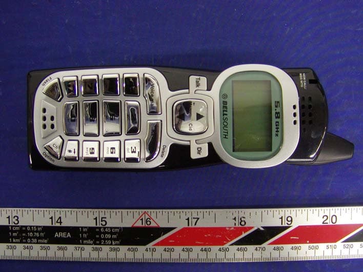
O63GH5815HALD04
Apr 15, 2004Analog Cordless Phone
Equipment Class
DXX - Part 15 Low Power Communication Device Transmitter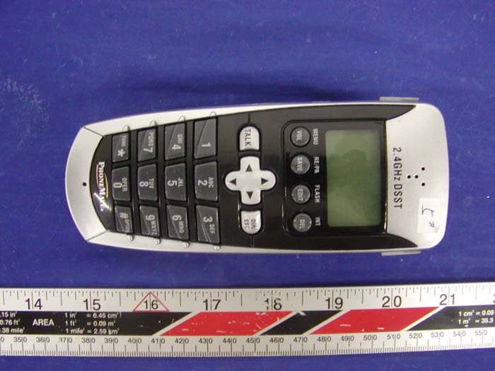
O63PM3320DLD04
Apr 05, 20042.4GHz Digital Spread-Spectrum Cordless Phone
Equipment Class
DTS - Digital Transmission System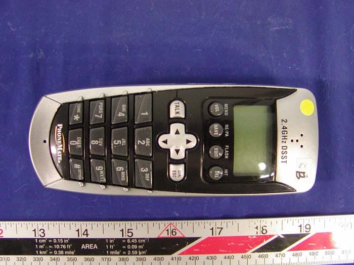
O63PM3375DLD04
Mar 29, 20042.4GHz Digital Spread-Spectrum Cordless Phone
Equipment Class
DTS - Digital Transmission System
O63GH5850BDLD03
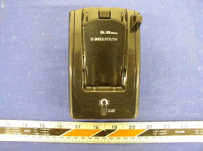
Nov 30, 2003Digital Cordless Phone � Base Unit
Equipment Class
DTS - Digital Transmission System