O6E70112BMultibandwidth portable transceiver
Midland Radio Corporation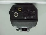
Click to zoom
Application Details
- Equipment Class
- TNF - Licensed Non-Broadcast Transmitter Held to Face
- Date of Grant
- Sep 10, 2000
- Application Purpose
- Original Equipment
- Date of Application
- Aug 06, 2000
- Equipment Note
- Multibandwidth portable transceiver
- Frequency Range
- 148.00000000 - 174.00000000
- Company
- Midland Radio Corporation
- Country
- United States
Documents & Files
Document Text
Text extracted from the exhibit documents filed with the FCC. Open a document above to read the original.
Users Manual
0CONTENTSGENERAL FEATURES ................................................. 1UNPACKING .................................................................. 2OPTIONAL ACCESSORIES ......................................... 2 GETTING READY.......................................................... 3DESCRIPTION............................................................... 4OPERATION .................................................................. 6CHARGER AND BATTERY .......................................... 8SPECIFICATIONS ......................................................... 9 General Features 1. Ultra compact design & size (102 x 50 x 43.2mm, 335g with high capable battery)2. Heavy durable construction3. 16 channels4. 38 CTCSS/ 83 CDCSS5. PC Programmable, transferable by cloning6. Time-out timer (TOT)7. Busy channel lock-out (BCLO)8. Battery saving mode9. Low battery alert10. DTMF PTT-ID11. Button lockable12. Talking range to 5 miles13. Transmit output power High/Low14. DC7.5V Ni-MH battery 1 α UnpackingUnpack and check that all items have been enclosed.Packing contents: radio α antenna β batterypack (1,350mA) χ belt cilp δ ha nd strap ε charger φ user`s manual Optional Accessories1. External earphone & MIC. (APE–10)2. Additional battery pack (720 mAH, HM–720) Getting Ready1. Installation, Removal Belt Clip Installation : align the belt clip with the plastic slots of the battery pack. Slidethe belt clip onto the battery pack,pushing firmly until a click heard.Removal : hold up the belt clip release tab with a fingernail or a coin (or likeinstrument). While holding up therelease tab, slide the belt clip out and away from thebattery pack. 2. Installation, Removal Battery Pack Installation : turn off the transceiver. Hold the transceiver with the back of the unit facing up. Place the batterypack against the back of the transceiver so that the tabson the transceiver engage the four openings in thebattery pack. Slide the battery pack toward the top of thetransceiver until a click heard.Removal : turn off the transceiver. Hold the radio with the back of the unit facing up. With the thumbnail of yourother hand slide the latch lever down. While holding thelatch lever down, slide the battery pack down toward thebottom of the transceiver. Separate the battery packfrom the transceiver. 3. Installation Antenna Rotate the antenna clockwise until itis seated firmly.*. Before your starting operation, makesure the battery is fully charged. 2 3 α βα χ δεφ Description∠ Power on / off and Volume Control Switch Turn the transceiver on by rotating power on / off andvolume control switch clockwise and control the volume. ∇ Channel Select knob Rotate the Channel Selector as you desire channelnumber. Speaker . Helical Antenna. Tx / Rx Indicate LED (3 colors) On Transmitting Red Blinking Low battery On Receiving, monitoring Green Blinking Different sub-tone when receiving Orange On Initializing, programming andcloning ∏ External Earphone/MIC and Programming Jack Socket √ Ha nd St r ap ⋅ Antenna Connector ¬ PTT(Push To Talk) Button Hold down to transmit, release to receive.∧ Function Button Refer to “OPERATION” page 7.∨ Monitor Button Press to monitor. Holding down over 2 seconds keepsmonitoring function on, and press shortly again or PTTButton to stop. ⇔ Belt Clip ⇐ Battery Pack 4 ∠ ∇ ∏ √ ⋅¬ ∧ ∨ ⇔ ⇐ 5 Operation1. Power Turn on / off and Volume Control Rotate the Power on/off and Volume Control Switch ∠ clockwise to turn power on, then the LED √ lights orange and power–up tone is generated after about on second,indicating the transceiver has passed the self–diagnostic.When you turn on the transceiver, it comes samechannel and function with your last using. Rotate thisswitch ∠ clockwise to increase the volume or counterclockwise to reduce the volume. Rotate it ∠ counterclockwise fully to turn power off. 2. Channel Selecting Rotate the Channel Select knob as you desire a channelnumber. 3. Transmit Hold dow n the PTT Button ¬ and talk to MIC in 5~7Cm distance. The LED lights red on transmitting. Release the PTT button ¬ to stop transmitting. 4. Receive Choose the channel by pressing Channel Select Button ∇ as you desire. The LED lights green on receiving. In case the signal doesn’t match in using sub–tone, greenlight blinks. 5. Monitor Press the Monitor Button ∨ to monitor. Holding down Monitor Button ∨ over 2 seconds keeps monitoring function on, and press Monitor Button ∨ shortly or press PTT Button ¬ to stop. 6. Scan 1). Scan will be started by press and hold t he functionbutton more than 1 second. In case Priority Scan not settled down1) mem 1ch > mem 2ch > mem 3ch > .....In case 1 cannel of Priority Scan is settled down2) mem 1ch > pri ch > mem 2ch > pri ch > .....In case 2 cannels of Priority Scan are settled down3) mem 1ch > pri 1ch > pri 2ch > mem 2ch > ..... 2). Tx channel of scanning a). Priority type : priority channel(the channel that is setby the channel selector) b). Non priority type : last busy channel3). While in scanning mode, function button is pressed 2times rapidly the radio will retur n to the last busy channel The priority channel remained the channel that isindicated by channel selector.4). While the radio is stopped scanning on a busychannel, pressing the monitor button w ill cause scan to resume and temporarily bypass the busy channel. If thechannel become busy again scan w ill stop. 5). While the radio is stopped scanning on a busychannel, press and hold the monitor button more than 1second will cause this channel to be deleted from scanlist until scan list is reset. 7. Selcall function : will be added.... 5 7 6 On Charging Red Blinking Abnormal battery Green On Fully charged On Stand-byforcharging(rear cup) Orange Bli nk i ng disc hargi ng Charger and Battery1. Battery (Ni-MH) Voltage DC 7.5V HM-1350 Over 8 hrs Duty time(5-5-90) HM-720 Over 4 hrs 2. Charger Input power Free voltage (AC90~250V) Charging time HM-1350 Appr. 100min HM-720 Appr. 60min Operating temperat…
Text truncated - open the document above for the full version.
External Photos
Back View Front View Top View
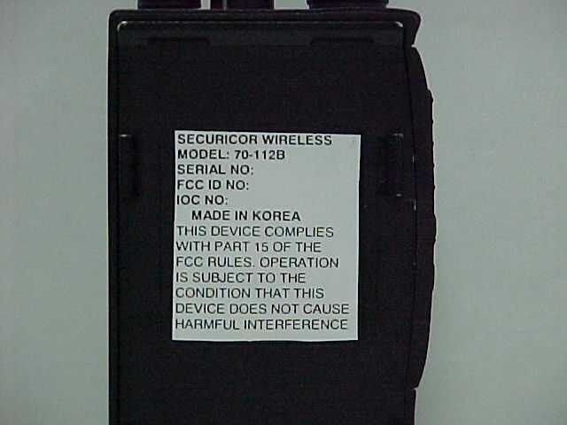
ID Label/Location Info
SECURICOR WIRELESS MODEL: 70-112B SERIAL NO: FCC ID: O6E70112B IOC NO: MADE IN KOREA THIS DEVICE COMPLIES W ITH PART 15 OF THE FCC RULES. OPERATION IS SUBJECT TO THE COND ITION THAT THIS DEVICE DOES NOT CAUSE HARMFUL INTERFERENCE
Internal Photos
CPU Back CPU Front
Parts List/Tune Up Info
IC,VOLTAGE DETXC61AC4002MRTOREX IC,LINEAR,OPAMP,SMDLM2902DMOTOROLA IC,LINER,SWITCH,SMDMC14066MOTOROLA IC,ASP,SMDFX828D5CML IC,CPU,SMDUPD75P3018AGK-be9NEC IC,MEM,EEPROM,SMD24C16I-2.7ATMEL IC,LINEAR,REG,SMDTK11250AMTOKO IC,LINEAR,AUDIO AMP,DIPNJM2073DJRC TR,SW,SMDKRA302KEC TR,SW,SMDKTA2014KEC TR,SW,SMDKTA1001YKEC TR,SW,SMDKTC4075KEC TR,SW,SMDKRC411KEC TR,SW,SMDKRC412KEC DIODE,SW,SMDKDS121KEC IC,LINEAR,REG,SMDTK11250AMTOKO IC,LINEAR,REG,SMDTK11455AMTOKO IC,IF DET,SMDBA4116FVROM IC,LINEAR,OPAMP,SMDNJM2107FJRC IC,SMDPF0314HITACHI IC,PLL,SMDU2781BTEMIC FET,MIXER,SMD3SK240TEMIC TR,RF,SMD2SC4226NEC TR,SW,SMD2SC3356NEC TR,SW,SMDKRC411KEC TR,SW,SMDKRC412KEC TR,SW,SMDKTC4080KEC TR,SW,SMDKTA4377KEC TR,SW,SMDKTA2014KEC TR,SW,SMDKRA302KEC TR,RF,SMDBCX-51PHILIPS DIODE,SW,SMDHSM88ASTLHITACHI DIODE,SW,SMDUPP9401SEMI DIODE,SW,SMDKDS120KEC DIODE,SW,SMDKDS121KEC DIODE,VVC,SMD1SV270TOSHIBA DIODE,VVC,SMD1SV229 T8TOSHIBA DIODE,RECTI,SMDS1GTIWAN VC TCXOVX-23VB(12.8MHZ)JVC
Test Report
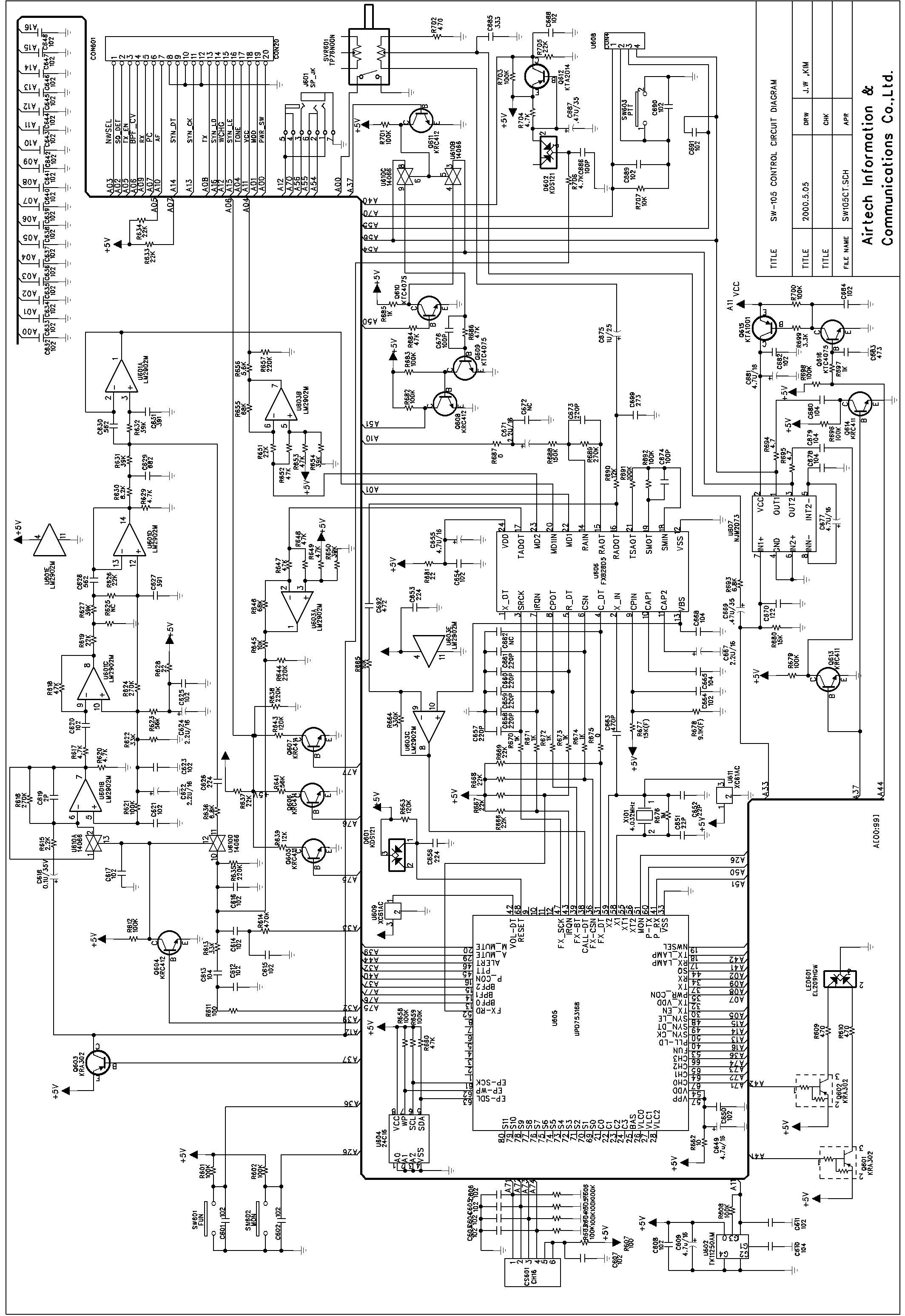
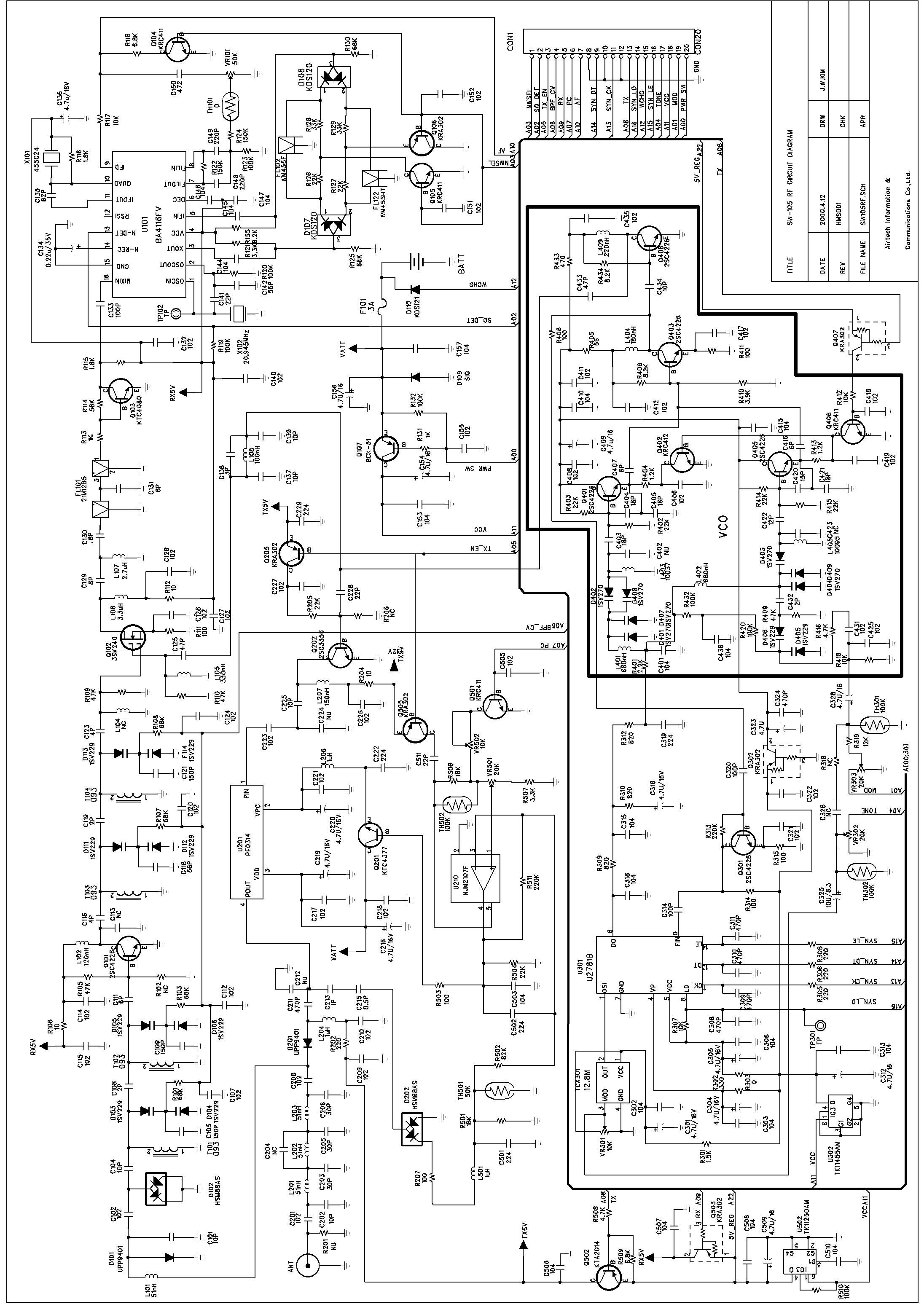
ENGINEERING STATEMENT For Type Certification of SECURICOR WIRELESS Model No: 70-112B FCC ID: O6E70112B I am an Electronics Engineer, a principal in the firm of Hyak Laboratories, Inc., Springfield, Virginia. My education and experience are a matter of record with the Federal Communications Commission. Hyak Laboratories, Inc. has been authorized by Securicor Wireless to make type certification measurements on the 70-112B transceiver. These tests made by me or under my supervision in our Springfield laboratory. Test data and documentation required by the FCC for Type Certification are included in this report. The data verifies that the above mentioned transceiver meets FCC requirements and Type Certification is requested. ______________________________ Rowland S. Johnson Dated: July 24, 2000 A. INTRODUCTION The following data are submitted in connection with this request for Type Certification of the 70-112B transceiver in accordance with Part 2, Subpart J of the FCC Rules. The 70-112B is a multi-bandwidth, VHF, frequency modulated transceiver intended for hand-held, portable applications in the 148 - 174 MHz band. It operates from a 7.5 volt battery pack. Output power rating is 5 watts. Both 25 kHz and 12.5 kHz channel operation is provided. B. GENERAL INFORMATION REQUIRED FOR TYPE CERTIFICATION (Paragraph 2.983 of the Rules) 1. Name of applicant: Maxon America, Inc. 2. Identification of equipment: O6E70112B a. The equipment identification label is submitted as a separate exhibit. b. Photographs of the equipment are submitted as a separate exhibit. 3. Quantity production is planned. 4. Technical description: a. 16k0F3E; 11k0F3E emission b. Frequency range: 148-174 MHz. c. Operating power of transmitter is fixed at the factory at 5 watts. d. Maximum power permitted under Part 90 of the FCC is 350 watts, and the 70-112B fully complied with those power limitations. e. The dc voltage and dc currents at final amplifier: Collector voltage: 7.3 Vdc Collector current: 1.3 A f. Function of active semiconductor device is submitted as a separate exhibit. g. Complete circuit diagram is submitted as a separate exhibit. h. A draft instruction book is submitted as a separate exhibit. i. The transmitter tune-up procedure is submitted as a separate exhibit. j. A description of circuits for stabilizing frequency is included in Appendix 1. 2 B. GENERAL INFORMATION... (Continued) k. A description of circuits and devices employed for suppression of spurious radiation and for limiting modulation is included in Appendix 2. l. Not applicable. 5. Data for 2.985 through 2.997 follow this section. C. RF POWER OUTPUT (Paragraph 2.985(a) of the Rules) RF power output was measured with a Bird 4421 RF power meter and a Narda 765-20 attenuator as a 50 ohm dummy load. Maximum power measured was 5.5 watts. (The transmitter was tuned by the factory.) D. MODULATION CHARACTERISTICS 1. A curve showing frequency response of the transmitter is shown in Figure 1. Reference level was audio signal output from a Boonton 8220 modulation meter with one kHz deviation. Audio output was measured with a Audio Precision System One TRMS voltmeter and tracking generator. 2. Modulation limiting curves are shown in Figures 2a and 2b for wide or narrow channel operation respectively, using a Boonton 8220 modulation meter. Signal level was established with a Audio Precision System One TRMS voltmeter. The curves show compliance with paragraphs 2.987(b), and 90.211(c). 3. Figure 3 is a graph of the post-limiter low pass filter which meets the requirements of paragraph 90.211(d)(1) in providing a roll-off of 60Logf/3 dB where f is audio frequency in kHz. Measurements were made following EIA RS-152B with an Audio Precision System One selective voltmeter on the Boonton 8220 modulation meter audio output. 3 D. MODULATION CHARACTERISTICS (Continued) 4. Occupied_Bandwidth (Paragraphs 2.989(c), 90.209(b)(4) and 90.210(d) of the Rules) Figures 4a, and 4b, are plots of the sideband envelope of the transmitter for 5.5 watt output taken with a Advantest R3361A spectrum analyzer. Modulation corresponded to conditions of 2.989(c)(1) and consisted of 2500 Hz tone at an input level 16 dB greater than that necessary to produce 50% modulation at 2417 Hz, the frequency of maximum response. Measured modulation under these conditions was 4.4 kHz, or 2.2 kHz for 25 or 12.5 kHz channelization respectively. For the 12.5 kHz channelization, RBW was 100 Hz, VBW 100 Hz, max hold, multiple scan per 90.210(d)(4). All plots have unmodulated carrier as 0 dBm reference. 4 FIGURE 1 MODULATION FREQUENCY RESPONSE MODULATION FREQUENCY RESPONSE FCC ID: O6E70112B FIGURE 1 5 FIGURE 2a AUDIO LIMITER CHARACTERISTICS AUDIO LIMITER CHARACTERISTICS FCC ID: O6E70112B FIGURE 2a Wideband (5 kHz) 6 FIGURE 2b AUDIO LIMITER CHARACTERISTICS AUDIO LIMITER CHARACTERISTICS FCC ID: O6E70112B FIGURE 2b Narrow band (2.5 kHz) 7 FIGURE 3 AUDIO LOW PASS FILTER RESPONSE AUDIO LOW PASS FILTER RESPONSE FCC ID: O6E70112B FIGURE 3 8 FIGURE 4a OCCUPIED BANDWIDTH ATTENUATION IN dB BELOW MEAN OUTPUT POWER Required On any frequency more than 50% up to and including 100% of the 25 authorized bandwidth, 20 kHz (10-20 kHz) On any frequency more than 100%, up to and including 250% of the 35 authorized bandwidth (20-50 kHz) On any frequency removed from the assigned frequency by more 43+10LogP = 50 than 250% of the authorized (P = 5.5 W) bandwidth (over 50 kHz) OCCUPIED BANDWIDTH (5.5 W) FCC ID: O6E70112B FIGURE 4a (5 kHz) 9 FIGURE 4b OCCUPIED BANDWIDTH ATTENUATION IN dB BELOW MEAN OUTPUT POWER Required On any frequency from the center of the authorized bandwidth f o 0 (>5.625 kHz) to 5.625 kHz removed from f o . On any frequency removed from the center of the authorized bandwidth 70 (@ 12.5 kHz) by a displacement frequency (f d in kHz) of more than 5.625 kHz but no more than 12.5 kHz: at least 7.27 (f d - 2.88 kHz) dB. On any frequency removed from the 50+10LogP = 57 (>12.5 kHz) center of the authorized bandwidth (P …
Text truncated - open the document above for the full version.
Contact Information
Applicant
Jeff Brame(Director of Engineering)
Technical Contact
Hyak Laboratories, Inc.Rowland S Johnson
[email protected](703) 451-1188
7011 Calamo St., Suite 107 · Springfield, Virginia · United States
Non-Technical Contact
Hyak Laboratories, Inc.Georgia Hall
[email protected](703) 451-1188
Test Firm
Hyak Laboratories, Inc.Rowland Johnson
703-451-1188
Technical Specifications
| # | Rule Parts | Frequency Range | Power Output | Emission | Tolerance |
|---|---|---|---|---|---|
| 2 | 9 | 148 MHz - 174 MHz | 5 W | 11k0F3E | 0.00025 % |
Other Applications from Midland Radio Corporation
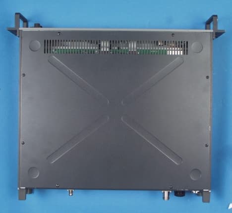
O6E710150B
Jan 25, 2001VHF Base Station/Repeater
Equipment Class
TNB - Licensed Non-Broadcast Station Transmitter
O6E710150C
Jan 16, 2001VHF Base Station/ Repeater
Equipment Class
TNB - Licensed Non-Broadcast Station Transmitter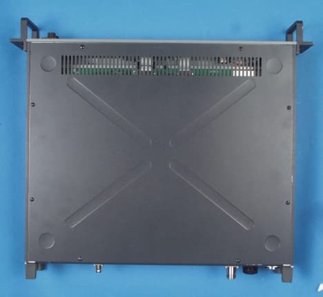
O6E713050B
Dec 04, 2000VHF Fixed Station Transceiver
Equipment Class
TNB - Licensed Non-Broadcast Station Transmitter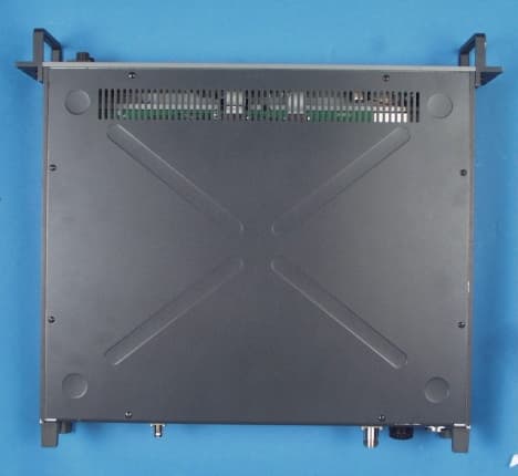
O6E714050B
Dec 04, 2000UHF Fixed Station Transceiver
Equipment Class
TNB - Licensed Non-Broadcast Station Transmitter