O6M-WE302PCMCIA 11 M Wireless LAN Radio Card
BroMax Communications Inc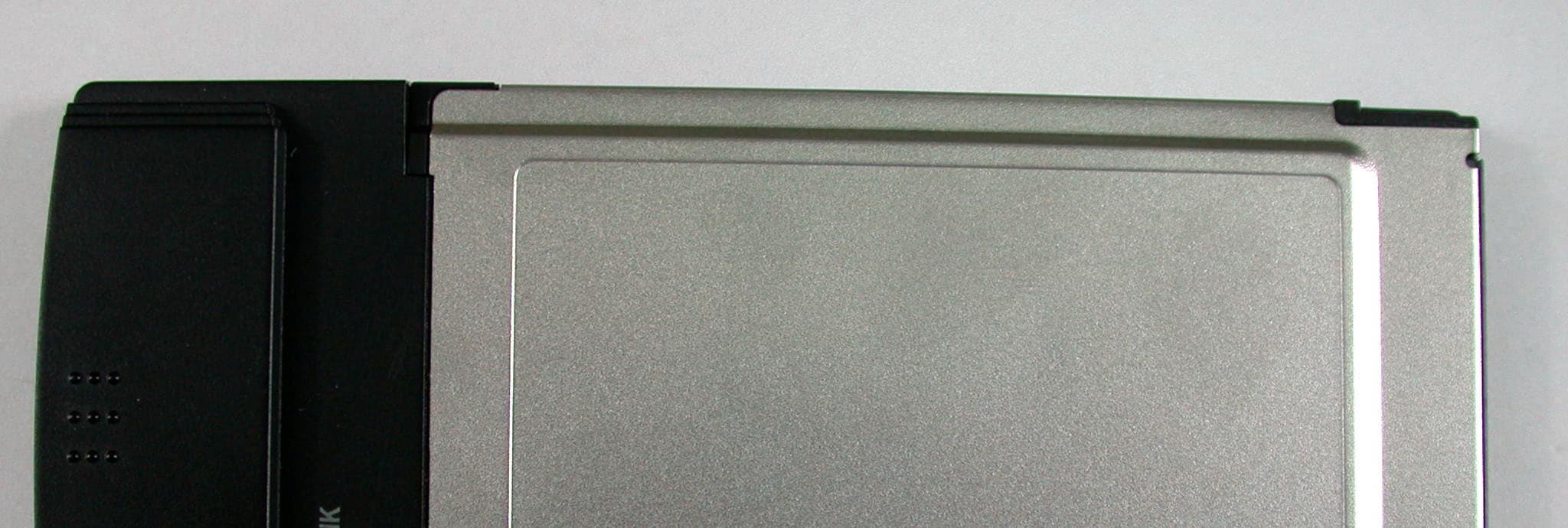
Click to zoom
Application Details
- Equipment Class
- DTS - Digital Transmission System
- Date of Grant
- Jul 22, 2002
- Application Purpose
- Original Equipment
- Date of Application
- Jul 22, 2002
- Equipment Note
- PCMCIA 11 M Wireless LAN Radio Card
- Frequency Range
- 2412.00000000 - 2462.00000000
- Company
- BroMax Communications Inc
- Country
- Taiwan
Documents & Files
Document Text
Text extracted from the exhibit documents filed with the FCC. Open a document above to read the original.
Users Manual
BROMAX COMMUNICATIONS, INC. No.20, Kuang Fu Road, Hsin Chu Industrial Park, Hu Kou,Hsin Chu 303, Taiwan, R.O.C. TEL: +886-03-597-2988*8370 FAX: +886-03-568-3414 [email protected] Inform Letter Dear Customer, According to FCC’s regulation, the following Declaration of Conformity has to be made by a company located in USA. They are: This device has been confirmed to be in compliance with the requirements of ANSI C63.4 & FCC part 15 regulations. The test result has been shown in the ADT test report with number RF910529R03A. And this compliance is subject to the following two conditions: (1) This device may not cause harmful interference and, (2) This device must accept any interference received, including interference that may cause undesired operation. This declaration can be a separate sheet and be sure that the following message will be also included in this declaration: 1) Product name, model name and trade name. 2) Company name, and address of the one who is responsible for this declaration. 3) Name, title, telephone and fax number as well as the signature of the contact person. Thanks for your attention.
Users Manual
PCMCIA Wireless LAN Card User’s Manual Rev 1.0 PCMCIA Wireless LAN Card User’ s Manual 2 Regulatory compliance FCC Warning This equipment has been tested and found to comply with the limits for a Class B digital device, pursuant to part 15 of the FCC Rules. These limits are designed to provide reasonable protection against harmful interference in a residential installation. This equipment generates, uses and can radiate radio frequency energy and, if not installed and used in accordance with the instructions, may cause harmful interference to radio communications. However, there is no guarantee that interference will not occur in a particular installation. If this equipment does cause harmful interference to radio or television reception, which can be determined by turning the equipment off and on, the user is encouraged to try to correct the interference by one or more of the following measures: ü Reorient or relocate the receiving antenna. ü Increase the separation between the equipment and receiver. ü Connect the equipment into an outlet on a circuit different from that to which the receiver is connected. ü Consult the dealer or an experienced radio/TV technician for help. You are cautioned that changes or modifications not expressly approved by the party responsible for compliance could void your authority to operate the equipment. IMPORTANT NOTE: Federal Communications Commission (FCC) Radiation Exposure Statement This equipment complies with FCC radiation exposure limits set forth for an uncontrolled environment. This equipment should be installed and operated with minimum distance 2.5cm between the radiator & your body. CE Mark Warning This is a Class B product. In a domestic environment, this product may cause radio interference, in which case the user may be required to take adequate measures. This transmitter must not be co-located or operation in conjunction with any other antenna or transmitter. PCMCIA Wireless LAN Card User’s Manual 3 About this manual This User’s Manual describes how to install and operate your PCMCIA Wireless LAN Card. Please read this manual before you install the product. This manual includes the following topics: ÿ Product description and features. ÿ Hardware installation procedure. ÿ Software installation procedure. ÿ FAQ PCMCIA Wireless LAN Card User’s Manual 4 Table of Contents Regulatory compliance................................................................................2 About this manual........................................................................................3 Chapter 1 - Introduction..................................................5 Features................................................................................................5 What is Wireless LAN?.........................................................................6 Wireless LAN Modes.............................................................................6 Notes on Wireless LAN Configuration..................................................7 Chapter 2 - Hardware Installation...................................8 Package Contents.................................................................................8 System Requirements for the Adapter..................................................8 Hardware description............................................................................8 Inserting the Wireless LAN Card...........................................................9 LED Indicators.......................................................................................9 Ejecting the Wireless LAN card..........................................................10 Chapter 3 – Driver Installation for Windows...................11 Driver installation for Windows 95 OSR2............................................11 Driver installation for Windows 98.......................................................14 Driver installation for Windows 2000..................................................17 Driver installation for Windows ME.....................................................20 Driver installation for Windows NT4.0.................................................22 Driver installation for Windows XP......................................................26 Chapter 4 – Installing and Using the Wireless Utility....28 Installation in Windows........................................................................28 Firmware Upgrade........................................................................31 Using Wireless Utility In Windows XP.................................................32 Use Windows Wireless Network Configuration............................32 Use Wireless LAN Utility...............................................................35 Use Wireless LAN Utility In Windows 95, 98, 2000, NT 4.0 and ME.38 Configuring the PCMCIA Wireless LAN Card.....................................39 Chapter 5 – Installing Network Protocols......................44 Installing the Network Protocols for Windows 98 and Millennium......44 Appendix A – FAQ........................................................47 Appendix B – Specifications.........................................48 PCMCIA Wireless LAN Card User’s Manual 5 Chapter 1 - Introduction Thank you for purchasing the PCMCIA Wireless LAN Card. This high-speed PCMCIA Wireless LAN Card provides you with an innovative wireless networking solution. The Adapter is easy to set up and use. With this innovative wireless technology, you can share files and printers on the network—without inconvenient wires! The Adapter is a network Adapter with a rate of 1, 2, 5.5, and 11 Mbps operating in the ISM band using Direct Sequence Spread Spectrum (DSSS) transmission implementing the IEEE 802.11b standard. This Adapter provides Device Drivers for Windows Operating Systems. It also provides tools for the configuration of the Adapter. The tool, as well as the installation steps of the plug-and-play procedure for the Windows oper…
Text truncated - open the document above for the full version.
Users Manual
PCMCIA Wireless LAN Card User’s Manual 26 Driver installation for Windows XP Follow the steps below to install the PCMCIA Wireless LAN Card drivers for Windows XP. 1. Insert the PCMCIA Wireless LAN Card to PCMCIA slot of notebook first. ( Refer to Chapter 2 – Hardware installation. ) 2. After Windows XP detects the PCMCIA Wireless LAN Card, the Found New Hardware Wizard window appears. Select Install the software automatically [Recommended] and insert the driver CD-ROM into CD-ROM drive and click Next to continue. PCMCIA Wireless LAN Card User’s Manual 27 3. Click Continue Anyway to continue the installation. 4. The Windows has finished installing software for the device. Click Finish to finish the installation Then system will start to install Wireless LAN Utility. Please refer to procedures at Chapter 4. PCMCIA Wireless LAN Card User’s Manual 28 Chapter 4 – Installing and Using the Wireless Utility The following sections cover the PCMCIA Wireless LAN Card utility installation and configuration. Installation in Windows After you have installed driver, system will start to install Wireless LAN Utility. Please follow the steps below to install the utility. 1. Once you see the following screen, click Next to continue. PCMCIA Wireless LAN Card User’s Manual 29 2. The screen will show you the default destination chosen by the utility. Click Next to continue or click the Browse button to select an alternate destination. 3. The following screen will add program icons to the Program Folder. You may type a new folder name or select one from the existing folders list. Click Next to continue or click Back to review or change any settings. PCMCIA Wireless LAN Card User’s Manual 30 4. The following screen shows the current settings, click Next to continue or click Back to change the Destination Folder in step 3. 5. The following screen shows you the Setup status by percentage. PCMCIA Wireless LAN Card User’s Manual 31 6. The Windows has finished installing Wireless LAN Utility. Click Finish to finish the installation. Firmware Upgrade After you have installed the utility, the firmware upgrade screen will appear if the firmware of the card is too old or not suitable for running on your environment. 1. Once you see the following screen, click OK to continue. 2. The Utility has finished upgrading firmware for the device. Click OK to finish the upgrade. PCMCIA Wireless LAN Card User’s Manual 32 Then you will see the Wireless LAN Utility icon in the Windows taskbar: Using Wireless Utility In Windows XP Wireless LAN Utility There are two ways to configure PCMCIA Wireless LAN Card. One is Wireless LAN Utility; the other one is Windows Wireless Network Configuration. Use Windows Wireless Network Configuration 1. Click the right key of the mouse and Exit Wireless LAN Utility. 2. Click Windows Wireless Network Configuration icon. Windows Wireless Network Configuration 3. Click Advanced button. PCMCIA Wireless LAN Card User’s Manual 33 4. Make sure “Use Windows to configure my wireless network settings” and click OK. PCMCIA Wireless LAN Card User’s Manual 34 5. Click the Windows Wireless Network Configuration icon again to open the Windows Wireless Network Configuration. Windows Wireless Network Configuration 6. Select an available network and click Connect button. 7. The Windows Wireless Network Configuration will be enabled. Click the Windows Wireless Configure icon. Windows Wireless Network Configuration is enabled PCMCIA Wireless LAN Card User’s Manual 35 8. Click Properties to start Windows Wireless Network Configuration. Use Wireless LAN Utility 1. Exit the Wireless LAN Utility. 2. Click Windows Wireless Network Configuration icon. Windows Wireless Network Configuration PCMCIA Wireless LAN Card User’s Manual 36 3. Click Advanced button. 4. Don’t select “Use windows to configure my wireless network settings” and click OK button. PCMCIA Wireless LAN Card User’s Manual 37 5. Click Start -> All Programs -> IEEE802.11b WLAN Card then click IEEE802.11b WLAN Card Utility to restart IEEE802.11b WLAN Card. 6. The Wireless LAN Utility will appear, Double-click the icon to open the configuration utility. Wireless LAN Utility
Users Manual
PCMCIA Wireless LAN Card User’s Manual 38 7. Click Re-Scan button to start Wireless LAN Utility. (Refer to Configuring the PCMCIA Wireless LAN Card.) Use Wireless LAN Utility In Windows 95, 98, 2000, NT 4.0 and ME Wireless LAN Utility icon IconMeaning Green: indicates a connection is linked to a wireless network. Red: indicates that the wireless LAN card is looking for an available access point. Double-click the icon to open the Wireless LAN Utility. (Refer to Configuring the PCMCIA Wireless LAN Card.) PCMCIA Wireless LAN Card User’s Manual 39 Configuring the PCMCIA Wireless LAN Card 1. This screen shows you the status of your current connection. Click Re-Scan to search for wireless connection (the adapter will search for the connection automatically when it is activated). 2. Select the “Configuration” tab. The profile setting allows you to save configurations in different profiles for different working environments. The default profile will contain the initial configuration setting when you install the Card. Under the Operating Mode drop-box, you may choose either Infrastructure or Ad-Hoc. The Infrastructure mode allows a wireless adapter to communicate with a wired network employing an Access Point, while the Ad-Hoc mode allows wireless-to- wireless, peer-to-peer communication. If you choose Infrastructure, the SSID should have the same name as the Access Point. If you choose Ad-Hoc, all clients should share the same SSID name. You may also select which Transfer Rate you wish to use: 1, 2, 5.5, 11Mbps or Auto Rate. Under Power Saving Mode, you can select Enabled to allow your adapter to go to sleep mode while the adapter doesn’t proceed the data transmission. Or select Disabled to make the adapter never go to sleep mode. Click Apply to save the settings. PCMCIA Wireless LAN Card User’s Manual 40 3. Select the “Site Survey” tab. The list on the adjacent screen shows you available Access Points and their features. Click on the desired Access Point, then click Connect to connect or Search to search for more Access Points. Click OK when you are finished. PCMCIA Wireless LAN Card User’s Manual 41 4. Click on the “Encryption” tab. Under the drop-box, you can choose to have WEP encryption Disabled, 64-Bit, or 128-Bit. Wired Equivalent Privacy (WEP) is an encryption scheme used to protect wireless data communication. The Disabled setting prevents the sharing of data with other computers on the WEP network. For data sharing to be enabled, select the level of encryption desired, either 64 or 128- bit. PCMCIA Wireless LAN Card User’s Manual 42 5. Select the “Advanced” tab. You can choose the fragmentation threshold to define the maximum data frame size your adapter will transmit. When the packet error rate is high, you may set the threshold value to transmit shorter frames. You may select RTS/CTS threshold to define when will your adapter send out RTS/CTS frames to reserve bandwidth for transmission. By using the RTS/CTS function, you may request bandwidth from AP to allow you have better chance to send out your data. For the Security, it’s only applicable while WEP is enabled. For the Authentication Type, the current supported algorithms are Open System, Shared Key, and Auto. The algorithm will be invoked when associated to Access Point. To associate to the desired Access Point you must set the same algorithm as the one of the desired Access Point. When select Auto mode, the driver can auto detect the Authentication Type of the Access Point you are going to associate. You can also select Preamble Type which is for framing synchronization. The possible setting are long and Short. The setting must be the same as the setting of the Access Point you are going to associate. PCMCIA Wireless LAN Card User’s Manual 43 6. The “About” tab shows you copyright and version information about the driver, the configuration utility, and the firmware. Click OK to complete the configuration. PCMCIA Wireless LAN Card User’s Manual 44 Chapter 5 – Installing Network Protocols Protocols are necessary for computers to be recognized on your network. Windows 2000 users need to check their Windows User Guides for protocol installation. Installing the Network Protocols for Windows 98 and Millennium 1. From the Start Menu, select Settings and bring up the Control Panel. From the Control Panel, double-click on the Network icon. Note: Before adding any network protocols, verify that the protocol is not already installed. Never install duplicate protocols. 2. Select IEEE802.11b WLAN PC Card v3.0 from the list and click the Add button. PCMCIA Wireless LAN Card User’s Manual 45 3. Highlight Protocol and click the Add button. 4. Select Microsoft from the list of “Manufacturers” and TCP/IP from the list of “Network” Protocols” and click the OK button to finish the installation. PCMCIA Wireless LAN Card User’s Manual 46 PCMCIA Wireless LAN Card User’s Manual 47 Appendix A – FAQ 1. What is IEEE 802.11 standard? ÿ The IEEE 802.11 is a wireless LAN industry standard, and the objective of IEEE 802.11 is to make sure that different manufactures’ wireless LAN devices can communicate to each other. 2. What is WEP? ÿ As described in the IEEE 802.11 standard, WEP (Wired Equivalent Privacy) is a data privacy mechanism based on a 40 bit shared key algorithm. 3. Windows cannot recognize the PCMCIA Wireless LAN Card. ÿ Please make sure that the LAN Card is inserted into the PCMCIA slot of your notebook properly (check this when the notebook is powered off). ÿ Please check if PC Card support is installed. Double-click the PC Card icon on Control Panel. If PC Card support is not activated, you should activate it now. 4. In Infrastructure mode, my notebook cannot communicate with the others notebooks on the network. ÿ First, make sure that the SSID is same as the others notebook. ÿ Check if the WEP is enabled on the Access Point, if it is, set your Adapter’s WEP the same as the Access Point. ÿ Also check the Access Point’s Authentication Type and …
Text truncated - open the document above for the full version.
Cover Letter(s)
American Telecommunications Certification Body Inc. 6731 Whittier Ave, McLean, VA 22101 July 23, 2002 RE: BROMAX COMMUNICATIONS, INC. FCC ID: O6M-WE302 After a review of the submitted information, I have a few comments on the above referenced Application. Please Note that SAR issued will be issued under a separate letter. 1) Please submit a DTS cover letter for this project. 2) The elements to each antenna are slightly different. Is the device capable of transmitting out of both antennas, or is one antenna only used for receive only? 3) The test report states that the EUT is designed with 2 outer appearances. Please provide specific information as to what these differences are. Are any of the differences changes in the metal, plastic, etc. 4) Please updated the EMC test report (page 44) to provide the calculations for the 3.9 GHz bandedge as well. 5) Please add the phrase "This transmitter must not be co-located or operating in conjunction with any other antenna or transmitter." to the FCC MPE section (page 2) of the users manual. Timothy R. Johnson Examining Engineer Direct Phone: 404-414-8071 mailto: [email protected] The items indicated above must be submitted before processing can continue on the above referenced application. Failure to provide the requested information may result in application termination. Correspondence should be considered part of the permanent submission and may be viewed from the Internet after a Grant of Equipment Authorization is issued. Please do not respond to this correspondence using the email reply button. In order for your response to be processed expeditiously, you must submit your documents through the AmericanTCB.com website. Also, please note that partial responses increase processing time and should not be submitted. Any questions about the content of this correspondence should be directed to the sender.
Cover Letter(s)
Dear Tim, For item 1,4, please find uploaded files on your website. For item 2, another antenna only used for receive. For item 3, this EUT is designed with two outer appearances that are different from their plastic cover only. Please refer to EUT Photo. For item 5, we do have the phrase shows in user's manual. Please find the last sentence on the bottom of page 2 of the user's manual. Regards, Rennie ----- Âà§eªÌ Rennie Wang/ADT ©ó 2002/07/24 01:47 PM ----- "Timothy R. Johnson" ¦¬¥ó¤H¡G [email protected] <tjohnson@Americ °Æ¥»§Û°e¡G [email protected], [email protected] anTCB.com> ¥D¦®¡G EMC Review of BROMAX COMMUNICATIONS, INC., FCC ID: O6M-WE302 2002/07/23 12:13 PM Alan, Attached are comments regarding review of this application. Please provide information as soon as possible. Thank You, Timothy R. Johnson NARTE Certified EMC Engineer No. EMC-002205-NE email: [email protected] alternate email: [email protected] (See attached file: ATCB Comments_072202_EMC.pdf) To: [email protected] Subject: EMC Review of BROMAX COMMUNICATIONS, INC., FCC ID: O6M-WE302 Page 1 of 2In 7/26/2002Printed for "Timothy R. Johnson" <[email protected]> =big5BQVRDQiBDb21tZW50c18wNzIyMDJfRU1DLnBkZg===.pdf Page 2 of 2In 7/26/2002Printed for "Timothy R. Johnson" <[email protected]>
Cover Letter(s)
American Telecommunications Certification Body Inc. 6731 Whittier Ave, McLean, VA 22101 July 23, 2002 RE: BROMAX COMMUNICATIONS, INC. FCC ID: O6M-WE302 After a review of the submitted information, I have a few comments on the above referenced Application. 1) The Maximum output power (conducted) or SAR drift measured at same position in liquid before and after each SAR test must be shown on each SAR plot? Please update the report to include this. 2) Test report must state (recommended on page 19 of 30): a) Identification of the device (was it considered mobile or portable transmitter device category) b) whether test device is production unit or identical prototype (47 CFR §2.908)? 3) Please provide a means to verify a phantom liquid depth. Depth must be 15 cm or more, per suppl. C and draft IEEE STD 1528. Please use photos, SAR vs. depth data (z-axis scan), or other means to demonstrate/verify liquid depth. 4) IEEE STD 1528 requires that the SAR test be performed at the high, middle, and low frequency channels of each operating mode. However, if the SAR measured at the middle channel for each test configuration is at least 2.0 dB lower than the SAR limit, testing at the high channels is optional (Note: this procedure is stated on page 6 & 17 of 30. The data provided is for the low channel only. Please provide data for the middle channel. 5) Please provide a description of the material/holder used to support the laptop. 6) Please justify and explain the use of a crest factor of 8. 7) A z-axis scan at the max SAR location must be provided. 8) OET Bulletin 65, Supplement C make mention of using the Flat Phantom Box for system verification. Please justify the use of this box for over the SAM phantom containing a flat body cavity. 9) Description of the phantom should detail shell thickness and other tolerances necessary to show it meets the phantom shell specifications. 10) Scan procedures given in the report appear to be for different phantoms. Please explain for the course scan: a) descriptions of coarse area scan procedures, including grid size, area shape and size b) specify which peak SAR location(s) were used to evaluate max 1-g SAR(s) c) report probe tip distance to phantom inner surface 11) Scan procedures given in the report appear to be for different phantoms. Please explain for the "zoom" scan: a) descriptions of high-resolution cube volume or “zoom” scan procedures used for local scan; list measurement and interpolation resolutions 12) The tissue parameters appear to be that of head tissue and not body tissue, please explain. 13) The tissue dielectric parameters and temperature should be measured at device mid-band frequencies. It appears that these were performed at the lower frequency. 14) SAR Plots must show: a) Ambient and liquid temperatures b) liquid temperatures during SAR testing must stay within ± 2° C. 15) The Tissue Parameters given on page 20 do not appear to match the parameters given on the test plots. Please explain. 16) Page 17 of 30 mentions "the above mentioned power values are conducted measured values..." . There is not any reported power values on this page. 17) Please provide a brief description of the reference source (e.g., 900, 1800 MHz dipoles) used to verify the SAR system performance. 18) Please provide the manufacturer/calibration reference dipole data. 19) Regarding the Field Probe: a) description of the probe – including tip diameter, internal sensor offset from tip, etc b) description of the probe measurement errors c) Description of probe calibration errors/uncertainties d) Please provide most recent calibration date and calibration certificate showing all factors used in report. - Continued on Next Page - z Page 2July 23, 2002 20) A list of measured tissue dielectric parameters, ambient and tissue temperatures must be provide for the system verification. These values must be within 5% of the values used in system manufacturer’s reference test. Timothy R. Johnson Examining Engineer Direct Phone: 404-414-8071 mailto: [email protected] The items indicated above must be submitted before processing can continue on the above referenced application. Failure to provide the requested information may result in application termination. Correspondence should be considered part of the permanent submission and may be viewed from the Internet after a Grant of Equipment Authorization is issued. Please do not respond to this correspondence using the email reply button. In order for your response to be processed expeditiously, you must submit your documents through the AmericanTCB.com website. Also, please note that partial responses increase processing time and should not be submitted. Any questions about the content of this correspondence should be directed to the sender.
Cover Letter(s)
American Telecommunications Certification Body Inc. 6731 Whittier Ave, McLean, VA 22101 August 1, 2002 RE: BROMAX COMMUNICATIONS, INC. FCC ID: O6M-WE302 After a review of the submitted information, I have a few comments on the above referenced Application. 1) Most device are placed underneath the phantom and the liquid depth above is specified to be 15 cm. However, this device was tested from the side of the box (vs. underneath) and therefore the distance as you move away from the device through the liquid (in this case will be horizontally) does not appear to give you 15 cm. Please justify acceptance of testing from the side of the box vs. underneath the box, given the liquid does not provide a 15 cm 'depth' as you move transversely away from the device. 2) Is manufacturer/calibration plots available for the dipole used for system verification that includes a list of measured tissue dielectric parameters, ambient and tissue temperatures during the calibration. These values (ε & σ) should be within 5% of those used during testing. 3) The test report only provides test data for the lowest channel. However the procedure given in the test report (which also match 1528/supplement C) on page 6 of 30 (last paragraph) and page 17 of 30 (last paragraph) state that the middle channel is tested first and if this is at least 2 dB below the SAR limit, the high and low channel is optional. Please provide further justification for only providing data for the lowest channel. 4) A field probe must be calibrated in tissue media with the target dielectric parameters specified in Appendix C of IEEE 1528, corresponding to the operating frequency ranges of the test device. Probe conversion factors by extrapolation is not allowed for TCB approval and the calibration should be performed within 5% target dielectric property window for the testing performed (dielectric information was not specified in calibration information). Please provide probe calibration information for the 2.4 GHz band measured. Also please note that the SAR correction factors listed in the report and were used are not exactly as those that appear on the calibration information already provided. 5) The test report claims a Crest Factor of 8. We understand that you are awaiting justification from the manufacturer. 6) When measuring pulsed signals with low duty factors or high peak-to-average ratios, the probe must be calibrated with correction factors to accurately measure SAR with respect to the average power. Given a Crest Factor of 8, please provide information regarding the probes correction factors for low duty cycles. Timothy R. Johnson Examining Engineer Direct Phone: 404-414-8071 mailto: [email protected] The items indicated above must be submitted before processing can continue on the above referenced application. Failure to provide the requested information may result in application termination. Correspondence should be considered part of the permanent submission and may be viewed from the Internet after a Grant of Equipment Authorization is issued. Please do not respond to this correspondence using the email reply button. In order for your response to be processed expeditiously, you must submit your documents through the AmericanTCB.com website. Also, please note that partial responses increase processing time and should not be submitted. Any questions about the content of this correspondence should be directed to the sender.
Cover Letter(s)
Hi Tim, Please find the attached three files for Q2,4 and 6. I am still waiting for Q 5 from BroMax If you can get from them? Liming > > Question 2) > I attach our performance statement for the dipoles supplied > (IXS0212.doc). > > Question 4) > I attach (SN0082cal2450.doc) a document setting out calibration > factors to be used at 2450MHz until such time as this probe receives its > next calibration. > > Question 6) > The pulsed performance of Indexsar probes is covered in the original > calibration document. This indicated, for probe 0082, that pulsed signals > would be correctly measured using the calibration supplied for CW signals. > > <<SN0082cal2450.doc>> <<SN0016_1900.doc>> <<IXS0212 new.doc>> SN0082cal2450.doc SN0016_1900.doc IXS0212 new.doc To: "'Timothy R. Johnson'" <[email protected]> Subject: RE: Questions 2,4 and 6 Page 1 of 1In 8/12/2002Printed for "Timothy R. Johnson" <[email protected]>
Cover Letter(s)
American Telecommunications Certification Body Inc. 6731 Whittier Ave, McLean, VA 22101 RE: THE LI NKSYS GROUP INC. FCC ID: O6M-WE302 After a review of the submitted information, I have a few comments on the above referenced Application. 1) The Maximum output power (conducted) or SAR drift measured at same position in liquid before and afte…
Text truncated - open the document above for the full version.
Contact Information
Applicant
Yung-Chao Tang(Director)
Technical Contact
Advance Data Technology CorporationAlan Lane
[email protected]+886-3-327-0910
13-1 Lane 19, WenShan 3rd., St. · Taoyuan · Taiwan
Non-Technical Contact
Advance Data Technology CorporationAlan Lane
[email protected]+886-3-327-0910
Test Firm
Bureau Veritas CPS (H.K.) Ltd. Taoyuan BranchTommy Wu
Technical Specifications
| # | Rule Parts | Frequency Range | Power Output |
|---|---|---|---|
| 1 | 15C | 2.41 GHz - 2.46 GHz | 70.00 mW |
Other Applications from BroMax Communications Inc
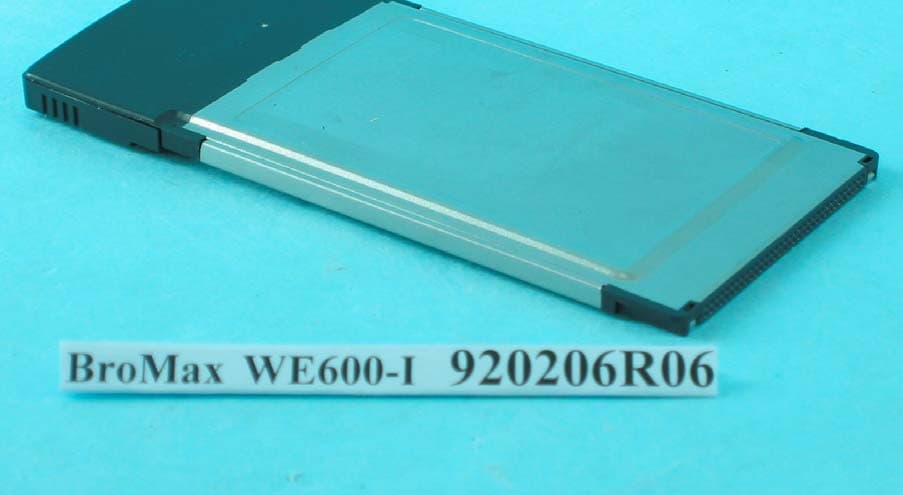
O6M-WE600I
Apr 13, 200354M WLAN Cardbus Adapter
Equipment Class
DTS - Digital Transmission System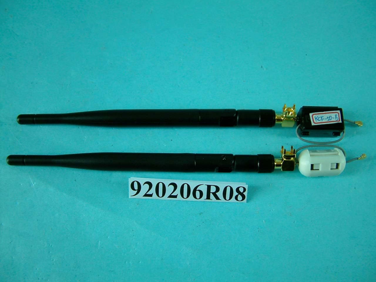
O6M-WM600I
Mar 30, 200354M WLAN Module
Equipment Class
DTS - Digital Transmission System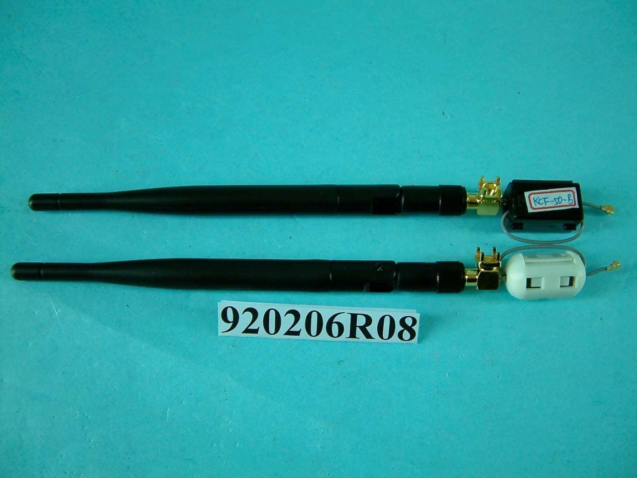
O6M-WM6001
Mar 25, 200354M WLAN Module
Equipment Class
DTS - Digital Transmission System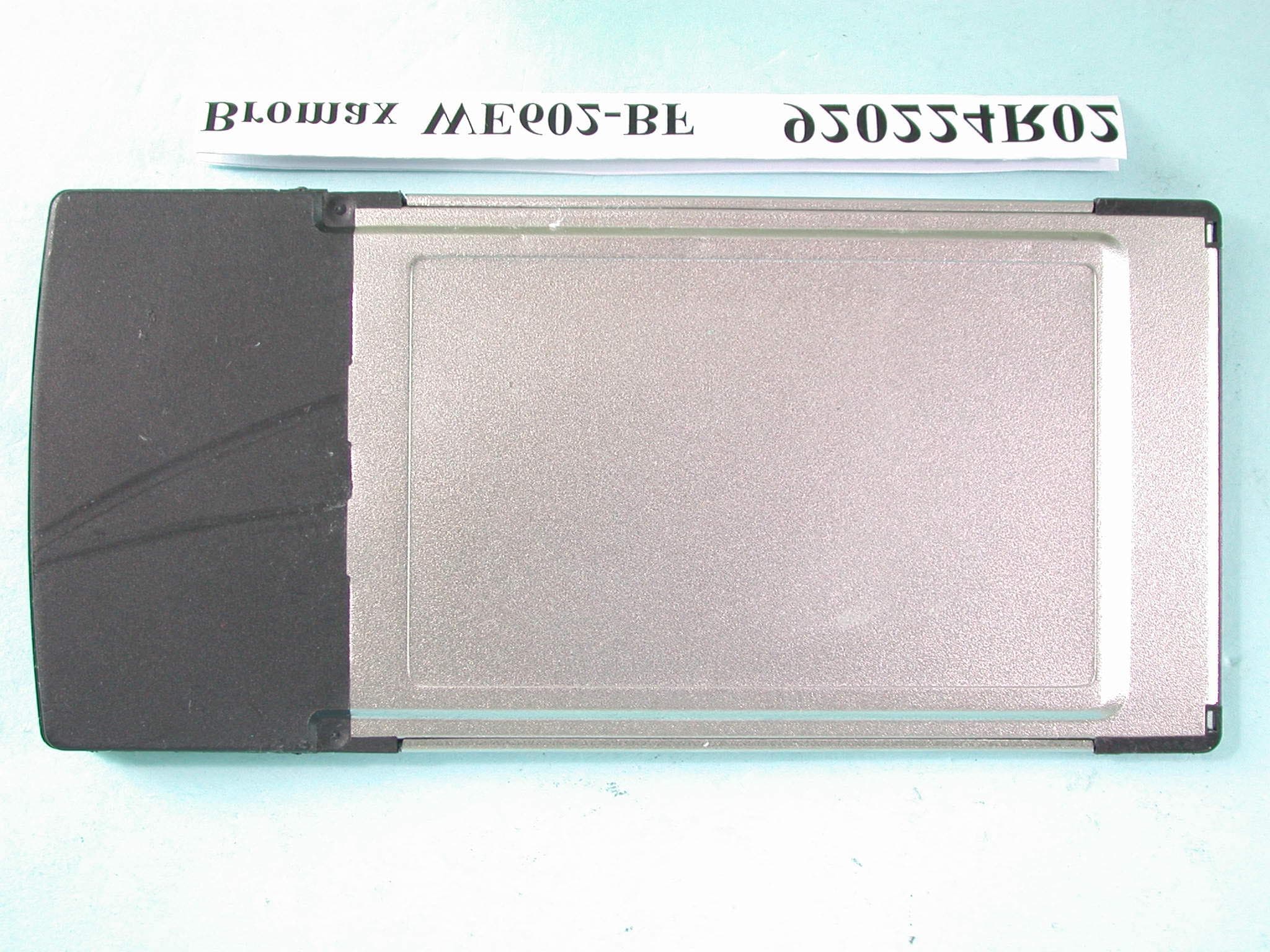
O6M-WE602B
Mar 12, 200354M Wireless LAN CardBus Card
Equipment Class
DTS - Digital Transmission System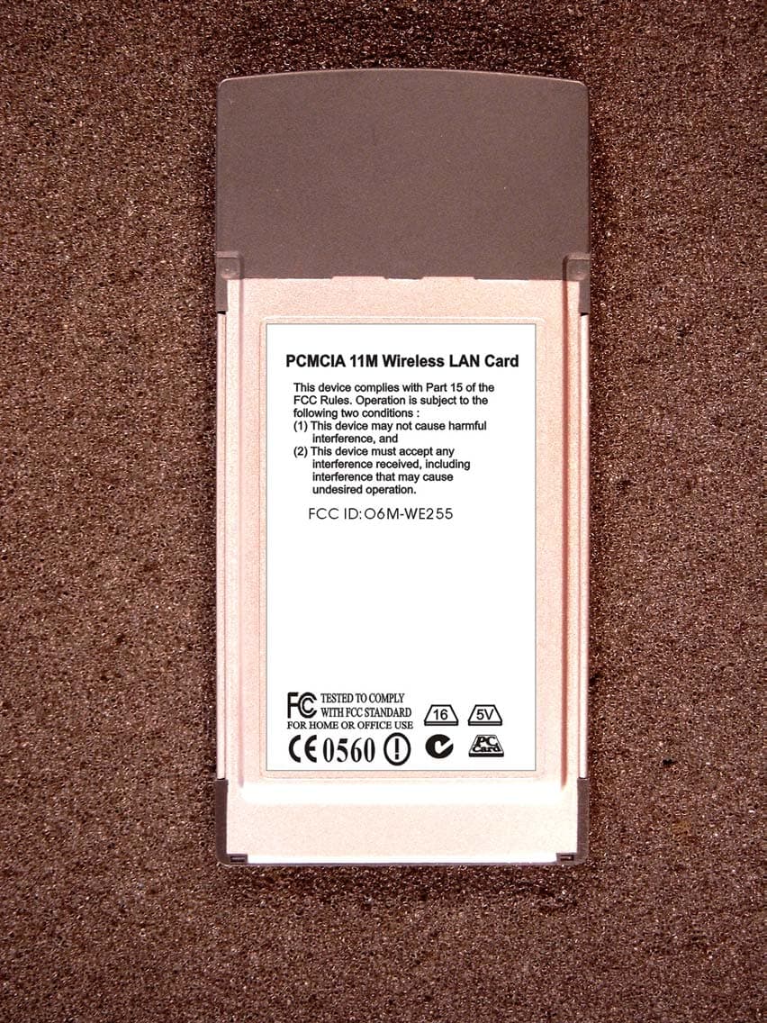
O6M-WE255
Jan 15, 20032.4 GHz WLAN PCMCIA Card
Equipment Class
DTS - Digital Transmission System