O6M-WE302TF11 Mbps WLAN Cardbus Card
BroMax Communications Inc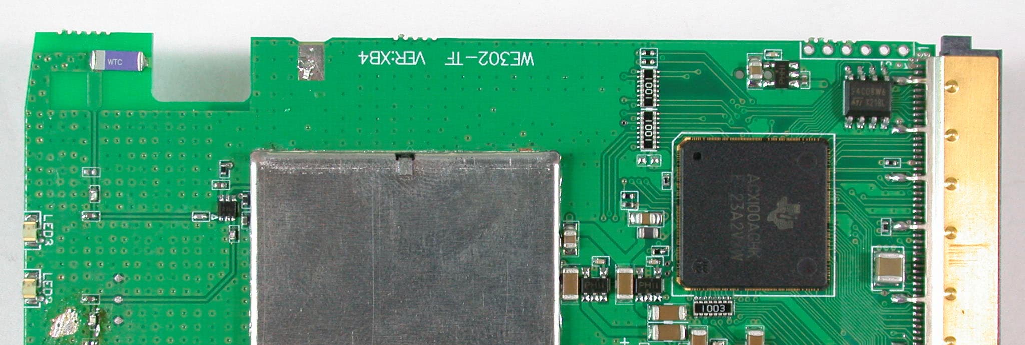
Click to zoom
Application Details
- Equipment Class
- DTS - Digital Transmission System
- Date of Grant
- Nov 04, 2002
- Application Purpose
- Original Equipment
- Date of Application
- Nov 04, 2002
- Equipment Note
- 11 Mbps WLAN Cardbus Card
- Frequency Range
- 2412.00000000 - 2462.00000000
- Company
- BroMax Communications Inc
- Country
- Taiwan
Documents & Files
Document Text
Text extracted from the exhibit documents filed with the FCC. Open a document above to read the original.
Users Manual
CardBus Wireless LAN Card User’s Manual Rev 0.9 CardBus Wireless LAN Card User’s Manual Regulatory compliance FCC Warning This equipment has been tested and found to comply with the limits for a Class B digital device, pursuant to part 15 of the FCC Rules. These limits are designed to provide reasonable protection against harmful interference in a residential installation. This equipment generates, uses and can radiate radio frequency energy and, if not installed and used in accordance with the instructions, may cause harmful interference to radio communications. However, there is no guarantee that interference will not occur in a particular installation. If this equipment does cause harmful interference to radio or television reception, which can be determined by turning the equipment off and on, the user is encouraged to try to correct the interference by one or more of the following measures: y Reorient or relocate the receiving antenna. y Increase the separation between the equipment and receiver. y Connect the equipment into an outlet on a circuit different from that to which the receiver is connected. y Consult the dealer or an experienced radio/TV technician for help. You are cautioned that changes or modifications not expressly approved by the party responsible for compliance could void your authority to operate the equipment. IMPORTANT NOTE: Federal Communications Commission (FCC) Radiation Exposure Statement This transmitter must not be co-located or operation in conjunction with any other antenna or transmitter. CE Mark Warning This is a Class B product. In a domestic environment, this product may cause radio interference, in which case the user may be required to take adequate measures. About this manual This User’s Manual describes how to install and operate your CardBus Wireless LAN Card. Please read this manual before you install the product. 2 CardBus Wireless LAN Card User’s Manual This manual includes the following topics: ¾ Product description and features. ¾ Hardware installation procedure. ¾ Software installation procedure. ¾ FAQ 3 CardBus Wireless LAN Card User’s Manual Table of Contents Regulatory compliance.............................................................................2 About this manual....................................................................................2 Chapter 1 - Introduction..................................................5 Features.............................................................................................5 What is Wireless LAN?......................................................................6 Wireless LAN Modes.......................................................................... 6 Notes on Wireless LAN Configuration................................................7 Chapter 2 - Hardware Installation....................................8 Package Contents..............................................................................8 System Requirements for the Adapter................................................8 Hardware description.........................................................................8 Inserting the Wireless LAN Card........................................................9 LED Indicators...................................................................................9 Ejecting the Wireless LAN card........................................................10 Chapter 3 – Driver Installation for Windows..................11 Driver installation for Windows 98....................................................11 Driver installation for Windows 2000................................................14 Driver installation for Windows ME...................................................17 Driver installation for Windows XP...................................................19 Chapter 4 – Installing and Using the Wireless Utility.....21 Installation in Windows.....................................................................21 Using Wireless Utility In Windows XP..............................................24 Use Windows Wireless Network Configuration......................................24 Use Wireless LAN Utility........................................................................27 Use Wireless LAN Utility In Windows 98, 2000 and ME...................30 Configuring the CardBus Wireless LAN Card...................................30 Chapter 5 – Installing Network Protocols......................34 Installing the Network Protocols for Windows 98 and Millennium.....34 Appendix A – FAQ.........................................................37 Appendix B – Specifications..........................................38 4 CardBus Wireless LAN Card User’s Manual Chapter 1 - Introduction Thank you for purchasing the CardBus Wireless LAN Card. This high-speed CardBus Wireless LAN Card provides you with an innovative wireless networking solution. The Adapter is easy to set up and use. With this innovative wireless technology, you can share files and printers on the network—without inconvenient wires! The Adapter is a network Adapter with a rate of 1, 2, 5.5, and 11 Mbps operating in the ISM band using Direct Sequence Spread Spectrum (DSSS) transmission implementing the IEEE 802.11b standard. This Adapter provides Device Drivers for Windows Operating Systems. It also provides tools for the configuration of the Adapter. The tool, as well as the installation steps of the plug-and-play procedure for the Windows operating systems, is described in this document. Features The CardBus Wireless LAN Card offers compliance with the IEEE 802.11b specification. This feature allows them to communicate with other wireless devices that support the standard. Features of the Adapter are: z Uses 2.4GHz frequency band, which complies with worldwide requirement z Wireless interface following the IEEE 802.11b standard z Using CardBus interface z Enciphering/deciphering of wireless data by the implementation of the WEP al…
Text truncated - open the document above for the full version.
Cover Letter(s)
American Telecommunications Certification Body Inc. 6731 Whittier Ave, McLean, VA 22101 October 25, 2002 RE: BROMAX COMMUNICATIONS INC. FCC ID: O6M-WE302TF After a review of the submitted information, I have a few comments on the above referenced Application. Please Note that SAR issues will be sent under a separate letter (when this exhibit has been provided). These comments are all made upon the assumption that the EUT's full conducted output power is 63.0 mW and the antenna gain is 1.0 dBi. EMC Issues 1) The block diagram should show the frequency of all oscillators in the device (CFR 2.1033(a)(5)). 2) The operational description explains the device is to be used with 2.5 cm spacing. The device may be used as a general purpose PCMCIA card in a variety of devices including laptops & PDA's, etc. (some of these devices may be used in the lap or while on the body). Therefore touch position IS considered applicable and the device must be subject to portable exposure conditions (2.5 cm separation distance is NOT considered applicable). Please remove the phrase "This equipment should be installed and operated with a minimum distance of 2.5 cm between the radiator and your body." from the users manual as this is not considered applicable. 3) The RF exposure information states 2.5 cm which is no longer considered valid. However, an email mentioned that a SAR report will be uploaded. This exhibit will replace the MPE calculations provided. 4) The users manual (page 38 of 38) states the EUT incorporates Strip Antennas, while the test report states Chip Antennas. Please correct these exhibits to be consistent. 5) Note: SAR REPORT NOT YET PROVIDED. Timothy R. Johnson Examining Engineer mailto: [email protected] The items indicated above must be submitted before processing can continue on the above referenced application. Failure to provide the requested information may result in application termination. Correspondence should be considered part of the permanent submission and may be viewed from the Internet after a Grant of Equipment Authorization is issued. Please do not respond to this correspondence using the email reply button. In order for your response to be processed expeditiously, you must submit your documents through the AmericanTCB.com website. Also, please note that partial responses increase processing time and should not be submitted. Any questions about the content of this correspondence should be directed to the sender.
Cover Letter(s)
American Telecommunications Certification Body Inc. 6731 Whittier Ave, McLean, VA 22101 November 5, 2002 RE: BROMAX COMMUNICATIONS INC. FCC ID: O6M-WE302TF After a review of the submitted information, I have a few comments on the above referenced Application. SAR Issues 1) A field probe must be calibrated in tissue media with the target dielectric parameters specified in Appendix C of IEEE 1528, corresponding to the operating frequency ranges of the test device. Probe conversion factors by extrapolation is not allowed for TCB approval and the calibration should be performed within 5% target dielectric property window for the testing performed (dielectric information was not specified in calibration information). It appears that the additional conversion factors provided by the manufacturer may be extrapolated factors. Please comment or provide additional probe calibration information for the 2.4 GHz band measured. 2) The test procedure does not appear to report probe tip distance to phantom inner surface during the scan. 3) The report does not appear to a) list measurement and interpolation resolutions of “zoom” scan procedures, b) contain descriptions of extrapolation procedures used to estimate SAR values adjacent to phantom surface, c) description of averaging (integration) procedures to get 1-g SAR from final interpolated grid. Please provide this information. Timothy R. Johnson Examining Engineer mailto: [email protected] The items indicated above must be submitted before processing can continue on the above referenced application. Failure to provide the requested information may result in application termination. Correspondence should be considered part of the permanent submission and may be viewed from the Internet after a Grant of Equipment Authorization is issued. Please do not respond to this correspondence using the email reply button. In order for your response to be processed expeditiously, you must submit your documents through the AmericanTCB.com website. Also, please note that partial responses increase processing time and should not be submitted. Any questions about the content of this correspondence should be directed to the sender.
External Photos
Page 1 ANNEX PHOTOGRAPHS OF EUT Page 2
Internal Photos
Page 3 Page 4 Page 5
Operational Description
FCC ID: O6M-WE302TF ADT No.910814R04 Operational Description The transmitter of the EUT is powered by host equipment. The antenna is Strip antenna. There is no antenna connector. The other instruction, please have a look at the users manual. DSSS Information This device is Direct Sequence Spread Spectrum, the data is mixed by pseudorandom code which is an orthogonal code. The mixed data is digital modulated by BPSK and QPSK technique depends on the data rates. The CCK coding is applied for increasing the data rate. The bit rates are 1,2,5.5,11,22Mbps, the symbol rates are 1,1,1.375,1.375,1.375 Mbps, the chip rates are always 11Mbps. So, the Chip/symbol is 11,11,8,8,and16 respectively. Although is higher bit rate, the processing gain is lower than 10, but the CCK coding used in higher bit rate will provide 2.2dB coding gain.
RF Exposure Info
Test Report S/N: 091002-278O6M Test Date(s): September 13, 2002 FCC SAR Evaluation © 2002 Celltech Research Inc.1 of 21 Celltech Research Inc. declares under its sole responsibility that this device was found to be in compliance with the Specific Absorption Rate (SAR) RF exposure requirements specified in FCC §2.1093 and was tested in accordance with the measurement standards and procedures specified in FCC OET Bulletin 65, Supplement C, Edition 01-01 (General Population / Uncontrolled Exposure). I attest to the accuracy of data. All measurements were performed by me or were made under my supervision and are correct to the best of my knowledge and belief. I assume full responsibility for the completeness of these measurements and vouch for the qualifications of all persons taking them. This test report shall not be reproduced partially, or in full, without the prior written approval of Celltech Research Inc. The results and statements contained in this report pertain only to the device(s) evaluated. Russell Pipe Senior Compliance Technologist Celltech Research Inc. DECLARATION OF COMPLIANCE SAR EVALUATION Test Lab CELLTECH RESEARCH INC. Testing and Engineering Lab 1955 Moss Court Kelowna, B.C. Canada V1Y 9L3 Phone:250-448-7047 Fax:250-448-7046 e-mail: [email protected] web site:www.celltechlabs.com Applicant Information BROMAX COMMUNICATIONS INC. No. 20, Kuang Fu Road, Hsin Chu Ind. Park Hu Kou, Hsin Chu 303 Taiwan R.O.C. FCC Rule Part(s):§2.1093 Test Procedure(s):FCC OET Bulletin 65, Supplement C (01-01) Device Classification:Part 15 Spread Spectrum Transmitter (DSS) FCC ID:O6M-WE302TF Brand / Model:BroMaxWE302-TF EUT Type:DSSS 11M WLAN Cardbus Card for Laptop PC Tx Frequency Range:2412 - 2462 MHz Conducted Power Tested:17.99 dBm (2412 MHz) 17.54 dBm (2437 MHz) 16.87 dBm (2462 MHz) Antenna Type:Internal Power Supply:from host Laptop PC Max. SAR Measured:0.989 W/kg Test Report S/N: 091002-278O6M Test Date(s): September 13, 2002 FCC SAR Evaluation © 2002 Celltech Research Inc.2 of 21 TABLE OF CONTENTS 1.0INTRODUCTION..................................................................... 3 2.0DESCRIPTION OF EUT............................................................ 3 3.0SAR MEASUREMENT SYSTEM ............................................... 4 4.0MEASUREMENT SUMMARY..................................................... 5 5.0DETAILS OF SAR EVALUATION............................................... 6 6.0EVALUATION PROCEDURES................................................... 7 7.0SYSTEM VALIDATION............................................................. 8 8.0EQUIVALENT TISSUES........................................................... 9 9.0SAR LIMITS........................................................................... 9 10.0SYSTEM SPECIFICATIONS......................................................10 11.0PROBE SPECIFICATION.......................................................... 11 12.0SAM PHANTOM......................................................................11 13.0DEVICE HOLDER.................................................................... 11 14.0TEST EQUIPMENT LIST...........................................................12 15.0MEASUREMENT UNCERTAINTIES............................................ 13 16.0REFERENCES........................................................................ 14 APPENDIX A - SAR MEASUREMENT DATA............................................. 15 APPENDIX B - SYSTEM VALIDATION.....................................................16 APPENDIX C - DIPOLE CALIBRATION...................................................17 APPENDIX D - PROBE CALIBRATION....................................................18 APPENDIX E - MEASURED FLUID DIELECTRIC PARAMETERS................19 APPENDIX F - SAM PHANTOM CERTIFICATE OF CONFORMITY..............20 APPENDIX G - SAR TEST SETUP & EUT PHOTOGRAPHS........................21 Test Report S/N: 091002-278O6M Test Date(s): September 13, 2002 FCC SAR Evaluation © 2002 Celltech Research Inc.BROMAX COMMUNICATIONS INC. FCC ID: O6M-WE302TF3 of 21 DSSS 11M WLAN Cardbus Card for Laptop PC (2412-2462MHz) 1.0 INTRODUCTION This measurement report demonstrates that BROMAX COMMUNICATIONS INC. Model: WE302-TF DSSS 11M WLAN Cardbus Card (for Laptop PC) FCC ID: O6M-WE302TF complies with the RF exposure requirements specified in FCC 47 CFR §2.1093 (see reference [1]). The test procedures described in FCC OET Bulletin 65, Supplement C, Edition 01-01 (see Reference [2]) were employed. A description of the product, operating configuration, detailed summary of the test results, methodology and procedures used in the evaluation, equipment used, and the various provisions of the rules are included within this test report. 2.0 DESCRIPTION of Equipment Under Test (EUT) FCC Rule Part(s) 47 CFR §2.1093 FCC Test Procedure OET Bulletin 65, Supplement C (01-01) FCC Device Classification Part 15 Spread Spectrum Transmitter (DSS) Device Type DSSS 11M WLAN Cardbus Card (for Laptop PC) FCC ID O6M-WE302TF Model(s) WE302-TF Serial No. Pre-production Tx Frequency Range 2412 - 2462 MHz RF Conducted Power Tested 17.99 dBm (2412 MHz) 17.54 dBm (2437 MHz) 16.87 dBm (2462 MHz) Antenna Type Internal Power Supply from host Laptop PC Test Report S/N: 091002-278O6M Test Date(s): September 13, 2002 FCC SAR Evaluation © 2002 Celltech Research Inc.BROMAX COMMUNICATIONS INC. FCC ID: O6M-WE302TF4 of 21 DSSS 11M WLAN Cardbus Card for Laptop PC (2412-2462MHz) 3.0 SAR MEASUREMENT SYSTEM Celltech Research SAR measurement facility utilizes the Dosimetric Assessment System (DASY™) manufactured by Schmid & Partner Engineering AG (SPEAG™) of Zurich, Switzerland. The DASY system is comprised of the robot controller, computer, near-field probe, probe alignment sensor, specific anthropomorphic mannequin (SAM) phantom, and various planar phantoms for brain or body SAR evaluations. The robot is a six-axis industrial robot performing precise movements to position the probe to the l…
Text truncated - open the document above for the full version.
RF Exposure Info
Celltech Research Inc. 1955 Moss Court, Kelowna, B.C. Canada V1Y 9L3 Tel. 250-448-7047 • Fax. 250-448-7046 • e-mail: [email protected] www.celltechlabs.com November 7, 2002 American Telecommunications Certification Body, Inc. 6731 Whittier Avenue McLean, VA 22101 Attn: Timothy Johnson SUBJECT: Bromax Communications Inc. FCC ID: O6M-WE302TF SAR Evaluation Dear Tim, On behalf of Bromax Communications Inc. is our response to your e-mail dated 11/05/02 requesting additional information for the subject application. 1. The probe conversion factors used for the evaluation were certified by the system manufacturer using numerical modeling. According to correspondence from Tim Harrington with the FCC on 11/06/02, system manufacturer’s certified probe conversion factors are permitted in accordance with Supplement C and P1528 draft. 2. The probe tip distance to phantom inner surface during the scan was 1.3 +/- 0.2 mm (probe manufacturer’s specification, shown in Appendix D of the SAR report). 3. Please refer to the attached revised SAR evaluation procedures (page 7 of SAR report). If you have any further questions or comments concerning the above, please contact the undersigned. Sincerely, Jonathan Hughes General Manager Celltech Research Inc. Test Report S/N: 091002-278O6M Test Date(s): September 13, 2002 FCC SAR Evaluation © 2002 Celltech Research Inc. BROMAX COMMUNICATIONS INC. FCC ID: O6M-WE302TF 7 of 22 DSSS 11M WLAN Cardbus Card for Laptop PC (2412-2462MHz) 6.0 EVALUATION PROCEDURES a. (i) The evaluation was performed in the applicable area of the phantom depending on the type of device being tested. For devices held to the ear during normal operation, both the left and right ear positions were evaluated in accordance with FCC OET Bulletin 65, Supplement C (Edition 01-01) using the SAM phantom. (ii) For body-worn and face-held devices a planar phantom was used. b. The SAR was determined by a pre-defined procedure within the DASY3 software. Upon completion of a reference and optical surface check, the exposed region of the phantom was scanned near the inner surface with a grid spacing of 20mm x 20mm. c. Based on the area scan data, the area of maximum absorption was determined by spline interpolation. Around this point, a volume of 40 x 40 x 35 mm (fine resolution volume scan, zoom scan) was assessed by measuring 5 x 5 x 7 points. d. The 1g and 10g spatial peak SAR was determined as follows: 1. The first step was an extrapolation to find the points between the dipole center of the probe and the surface of the phantom. This data cannot be measured, since the center of the dipoles is 2.7 mm away form the tip of the probe and the distance between the surface and the lowest measuring point is 1.3 mm (see probe calibration document in Appendix D). The extrapolation was based on a least square algorithm [W. Gander, Computermathematik, p.168-180]. Through the points in the first 3 cm in all z-axis, polynomials of the fourth order were calculated. This polynomial was then used to evaluate the points between the surface and the probe tip. 2. The next step used 3D-spline interpolation to get all points within the measured volume in a 1mm grid (35000 points). The 3D-spline is composed of three one-dimensional splines with the "Not a knot" condition [W. Gander, Computermathematik, p.141-150] (x, y and z -direction) [Numerical Recipes in C, Second Edition, p.123ff]. 3. The maximal interpolated value was searched with a straightforward algorithm. Around this maximum the SAR values averaged over the spatial volumes (1g or 10g) were computed using the 3D-spline interpolation algorithm. 8000 points (20x20x20) were interpolated to calculate the average.
Test Report
FCC ID: O6M-WE302TF Report No.: RF910814R041Issued: August 30, 2002 FCC TEST REPORT REPORT NO.: RF910814R04 MODEL NO.: WE302-TF RECEIVED: August 14, 2002 TESTED: July 16 ~ August 24, 2002 APPLICANT:BROMAX COMMUNICATIONS, INC. ADDRESS:No. 20, Kuang Fu Road, Hsin Chu Industrial Park, Hu Kou, Hsin Chu, Taiwan, R.O.C. ISSUED BY:Advance Data Technology Corporation LAB LOCATION:47 14th Lin, Chiapau Tsun, Linko, Taipei, Taiwan, R.O.C. This test report consists of 50 pages in total. It may be duplicated completely for legal use with the approval of the applicant. It should not be reproduced except in full, without the written approval of our laboratory. The client should not use it to claim product endorsement by CNLA, NVLAP or any government agencies. The test results in the report only apply to the tested sample. 0528 ILAC MRA Lab Code: 200102-0 FCC ID: O6M-WE302TF Report No.: RF910814R042Issued: August 30, 2002 Table of Contents 1CERTIFICATION...........................................................................................4 2SUMMARY OF TEST RESULTS...................................................................5 3GENERAL INFORMATION............................................................................6 3.1GENERAL DESCRIPTION OF EUT..............................................................6 3.2DESCRIPTION OF TEST MODES................................................................7 3.3GENERAL DESCRIPTION OF APPLIED STANDARDS...............................7 3.4DESCRIPTION OF SUPPORT UNITS..........................................................8 4TEST TYPES AND RESULTS.......................................................................9 4.1CONDUCTED EMISSION MEASUREMENT................................................9 4.1.1LIMITS OF CONDUCTED EMISSION MEASUREMENT..............................9 4.1.2TEST INSTRUMENTS..................................................................................9 4.1.3TEST PROCEDURES.................................................................................10 4.1.4DEVIATION FROM TEST STANDARD.......................................................10 4.1.5TEST SETUP..............................................................................................11 4.1.6EUT OPERATING CONDITIONS................................................................12 4.1.7TEST RESULTS..........................................................................................13 4.2RADIATED EMISSION MEASUREMENT...................................................19 4.2.1LIMITS OF RADIATED EMISSION MEASUREMENT.................................19 4.2.2TEST INSTRUMENTS................................................................................20 4.2.3TEST PROCEDURES.................................................................................21 4.2.4DEVIATION FROM TEST STANDARD.......................................................21 4.2.5TEST SETUP..............................................................................................22 4.2.6EUT OPERATING CONDITIONS................................................................22 4.2.7TEST RESULTS..........................................................................................23 4.36dB BANDWIDTH MEASUREMENT...........................................................28 4.3.1LIMITS OF 6dB BANDWIDTH MEASUREMENT........................................28 4.3.2TEST INSTRUMENTS................................................................................28 4.3.3TEST PROCEDURE...................................................................................29 4.3.4DEVIATION FROM TEST STANDARD.......................................................29 4.3.5TEST SETUP..............................................................................................29 4.3.6EUT OPERATING CONDITIONS................................................................29 4.3.7TEST RESULTS..........................................................................................30 4.4MAXIMUM PEAK OUTPUT POWER..........................................................34 4.4.1LIMITS OF MAXIMUM PEAK OUTPUT POWER MEASUREMENT...........34 4.4.2TEST INSTRUMENTS................................................................................34 FCC ID: O6M-WE302TF Report No.: RF910814R043Issued: August 30, 2002 4.4.3TEST PROCEDURES.................................................................................35 4.4.4DEVIATION FROM TEST STANDARD.......................................................35 4.4.5TEST SETUP..............................................................................................35 4.4.6EUT OPERATING CONDITIONS................................................................35 4.4.7TEST RESULTS..........................................................................................36 4.5POWER SPECTRAL DENSITY MEASUREMENT......................................37 4.5.1LIMITS OF POWER SPECTRAL DENSITY MEASUREMENT...................37 4.5.2TEST INSTRUMENTS................................................................................37 4.5.3TEST PROCEDURE...................................................................................38 4.5.4DEVIATION FROM TEST STANDARD.......................................................38 4.5.5TEST SETUP..............................................................................................38 4.5.6EUT OPERATING CONDITIONS................................................................38 4.5.7TEST RESULTS..........................................................................................39 4.6BAND EDGES MEASUREMENT................................................................43 4.6.1LIMITS OF BAND EDGES MEASUREMENT..............................................43 4.6.2TEST INSTRUMENTS................................................................................43 4.6.3TEST PROCEDURE......................................................…
Text truncated - open the document above for the full version.
Test Setup Photos
FCC ID: O6M-WE302TF Report No.: RF910814R0448Issued: August 30, 2002 5 PHOTOGRAPHS OF THE TEST CONFIGURATION CONDUCTED EMISSION TEST FCC ID: O6M-WE302TF Report No.: RF910814R0449Issued: August 30, 2002 RADIATED EMISSION TEST
Contact Information
Applicant
Yung-Chao Tang(Director)
Technical Contact
Advance Data Technology CorporationVivi Wang
[email protected]+886-3-327-0910
13-1, Lane19, WenShan 3rd., St. · Taoyuan · Taiwan
Non-Technical Contact
Advance Data Technology CorporationVivi Wang
[email protected]+886-3-327-0910
Test Firm
Bureau Veritas CPS (H.K.) Ltd. Taoyuan BranchTommy Wu
Technical Specifications
| # | Rule Parts | Frequency Range | Power Output |
|---|---|---|---|
| 1 | 15C | 2.41 GHz - 2.46 GHz | 63.00 mW |
Other Applications from BroMax Communications Inc
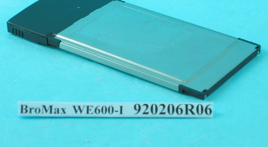
O6M-WE600I
Apr 13, 200354M WLAN Cardbus Adapter
Equipment Class
DTS - Digital Transmission System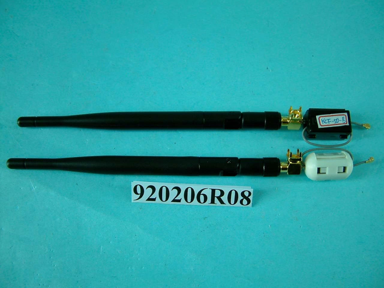
O6M-WM600I
Mar 30, 200354M WLAN Module
Equipment Class
DTS - Digital Transmission System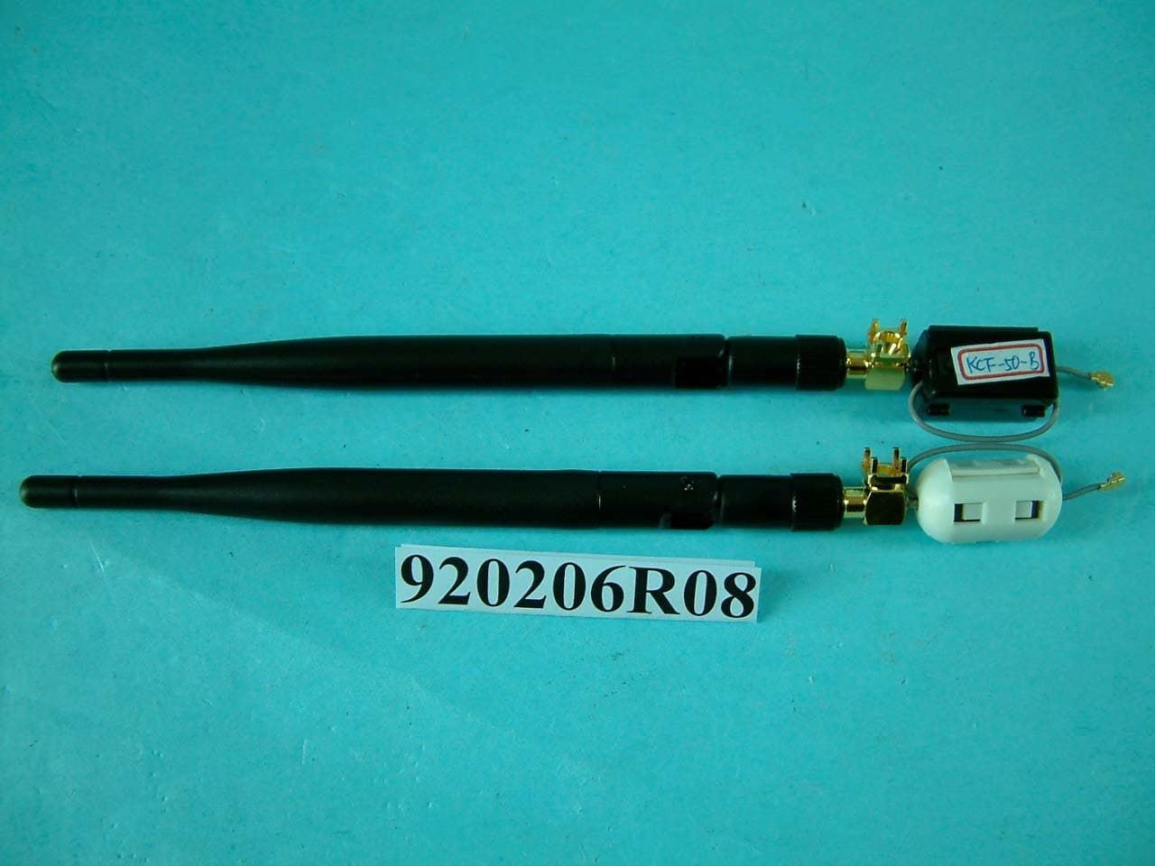
O6M-WM6001
Mar 25, 200354M WLAN Module
Equipment Class
DTS - Digital Transmission System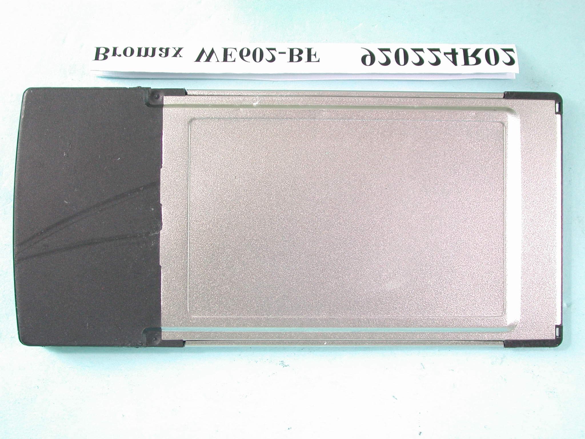
O6M-WE602B
Mar 12, 200354M Wireless LAN CardBus Card
Equipment Class
DTS - Digital Transmission System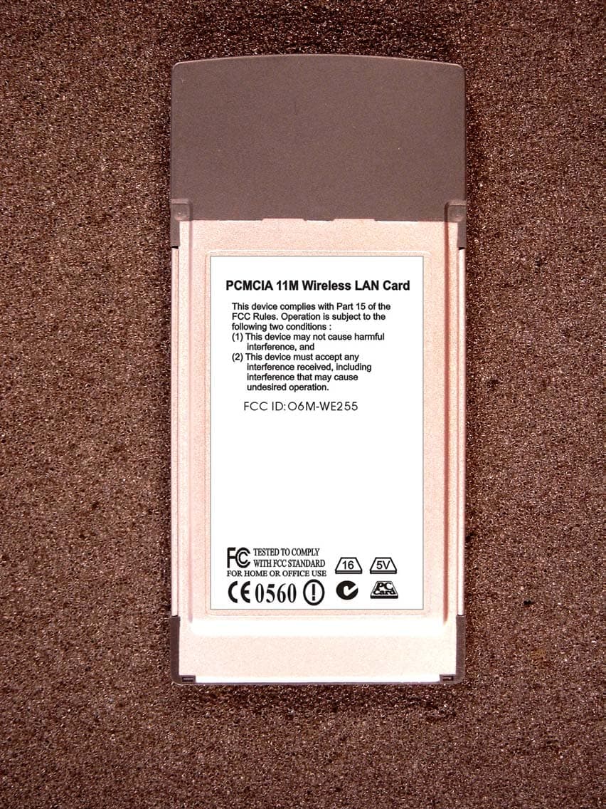
O6M-WE255
Jan 15, 20032.4 GHz WLAN PCMCIA Card
Equipment Class
DTS - Digital Transmission System