O6M-WE600BF54M WLAN CardBus Adapter
BroMax Communications Inc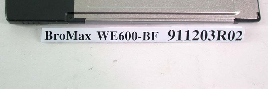
Click to zoom
Application Details
- Equipment Class
- DTS - Digital Transmission System
- Date of Grant
- Dec 28, 2002
- Application Purpose
- Original Equipment
- Date of Application
- Dec 28, 2002
- Equipment Note
- 54M WLAN CardBus Adapter
- Frequency Range
- 2412.00000000 - 2462.00000000
- Company
- BroMax Communications Inc
- Country
- Taiwan
Documents & Files
Document Text
Text extracted from the exhibit documents filed with the FCC. Open a document above to read the original.
Users Manual
54M Wireless LAN CardBus Adapter User’s Manual Rev 0.9 54M Wireless LAN CardBus Card User’s Manual Federal Communication Commission Interference Statement This equipment has been tested and found to comply with the limits for a Class B digital device, pursuant to Part 15 of the FCC Rules. These limits are designed to provide reasonable protection against harmful interference in a residential installation. This equipment generates, uses and can radiate radio frequency energy and, if not installed and used in accordance with the instructions, may cause harmful interference to radio communications. However, there is no guarantee that interference will not occur in a particular installation. If this equipment does cause harmful interference to radio or television reception, which can be determined by turning the equipment off and on, the user is encouraged to try to correct the interference by one of the following measures: - Reorient or relocate the receiving antenna. - Increase the separation between the equipment and receiver. - Connect the equipment into an outlet on a circuit different from that to which the receiver is connected. - Consult the dealer or an experienced radio/TV technician for help. FCC Caution: Any changes or modifications not expressly approved by the party responsible for compliance could void the user's authority to operate this equipment. This device complies with Part 15 of the FCC Rules. Operation is subject to the following two conditions: (1) This device may not cause harmful interference, and (2) this device must accept any interference received, including interference that may cause undesired operation. IMPORTANT NOTE: FCC Radiation Exposure Statement: This equipment complies with FCC radiation exposure limits set forth for an uncontrolled environment. This transmitter must not be co-located or operating in conjunction with any other antenna or transmitter. 2 54M Wireless LAN CardBus Card User’s Manual About this manual This User’s Manual describes how to install and operate your CardBus Wireless LAN Card. Please read this manual before you install the product. This manual includes the following topics: ¾ Product description and features. ¾ Hardware installation procedure. ¾ Software installation procedure. ¾ FAQ 3 54M Wireless LAN CardBus Card User’s Manual Table of Contents Regulatory compliance.............................................! About this manual......................................................................................3 Chapter 1 - Introduction...................................................5 Features..............................................................................................5 What is Wireless LAN?.......................................................................6 Wireless LAN Modes...........................................................................6 Notes on Wireless LAN Configuration.................................................7 Chapter 2 - Hardware Installation....................................8 Package Contents...............................................................................8 System Requirements for the Adapter................................................8 Hardware description..........................................................................8 Inserting the Wireless LAN Card.........................................................8 LED Indicators.....................................................................................9 Ejecting the Wireless LAN card.........................................................10 Chapter 3 – Driver Installation for Windows..................11 Driver installation for Windows 98.....................................................11 Driver installation for Windows 2000.................................................14 Driver installation for Windows ME....................................................17 Driver installation for Windows XP....................................................19 Chapter 4 – Installing and Using the Wireless Utility.....21 Installation in Windows......................................................................21 Using Wireless Utility In Windows XP...............................................24 Use Windows Wireless Network Configuration.....................................24 Use Wireless LAN Utility........................................................................27 Use Wireless LAN Utility In Windows 98, 2000 and ME...................30 Configuring the CardBus Wireless LAN Card...................................30 Chapter 5 – Installing Network Protocols......................34 Installing the Network Protocols for Windows 98 and Millennium.....34 Appendix A – FAQ.........................................................37 Appendix B – Specifications..........................................38 4 54M Wireless LAN CardBus Card User’s Manual Chapter 1 - Introduction Thank you for purchasing the CardBus Wireless LAN Card. This high-speed CardBus Wireless LAN Card provides you with an innovative wireless networking solution. The Adapter is easy to set up and use. With this innovative wireless technology, you can share files and printers on the network—without inconvenient wires! The Adapter is a network Adapter with a rate of 1, 2, 5.5, and 11 Mbps operating in the ISM band using Direct Sequence Spread Spectrum (DSSS) transmission implementing the IEEE 802.11b standard. This Adapter provides Device Drivers for Windows Operating Systems. It also provides tools for the configuration of the Adapter. The tool, as well as the installation steps of the plug-and-play procedure for the Windows operating systems, is described in this document. Features The CardBus Wireless LAN Card offers compliance with the IEEE 802.11b specification. This feature allows them to communicate with other wireless devices that support the standard. Features of the Adapter are: z Uses 2.4GHz frequency band, which complies w…
Text truncated - open the document above for the full version.
Cover Letter(s)
American Telecommunications Certification Body Inc. 6731 Whittier Ave, McLean, VA 22101 December 27, 2002 RE: FCC ID: O6M-WE600B Attention: Ellis Wu I have a few comments on this Application. 1 2.1033 states that Block diagrams are to have the osc/clock frequencies shown. Please show the clocks on the block diagram. 2 2.927(a) states, “A grant of equipment authorization is valid only when the FCC Identifier is permanently affixed on the device...” 2.925(d) states, “In order to validate the grant of equipment authorization, the nameplate or label shall be permanently affixed to the equipment and shall be readily visible to the purchaser at the time of purchase.” Please explain how the label is permanently affixed to the device. 3 Please note that PPSD is over any one MHz span. The plots you have provided show only 300kHz in the span. No information clearly states that the signal levels outside the SA span are compliant. Please verify that the signal levels above and below that which is shown on the plots out to 1MHz is compliant with the PPSD requirements of 15.247. 4 The FCC requires that a SAR report contain an adequate description of the test and test system. Please provide the following FCC required information that is missing from the SAR report: a) description of the probe – including tip diameter, internal sensor offset from tip, etc. b) mobile or portable transmitter device category identified. c) a description of the Phantom including a description of shell thickness and other tolerances (i.e. thickness 2 ± 0.2 mm for head and body phantoms, d) photos or z-axis scans to show 15 cm LIQUID DEPTH. e) description of the holding fixtures showing or explaining nonconductive nature of holding fixture. 5 Please review Z-Axis Extrapolation at Peak SAR Location as described in IEEE 1528 ( Extrapolation of SAR data to inner surface of the phantom based on a least-squares polynomial fit of the measured data) and explain your Z-axis results as shown on page 27 of the report. 6 The manual states that data rates up to 11mbs are possible, but the test report states up to 54mbs are possible. Documentation needs to be consistent. Please correct the manual to reflect the proper data rates. Dennis Ward mailto:[email protected] The items indicated above must be submitted before processing can continue on the above referenced application. Failure to provide the requested information may result in application termination. Correspondence should be considered part of the permanent submission and may be viewed from the Internet after a Grant of Equipment Authorization is issued. Please do not respond to this correspondence using the email reply button. In order for your response to be processed expeditiously, you must submit your documents through the AmericanTCB.com website. Also, please note that partial responses increase processing time and should not be submitted. Any questions about the content of this correspondence should be directed to the sender.
Cover Letter(s)
Hi Alan Items in your email are addressed as follows. Your item a)Probe information etc. Very simply put - the FCC will most likely dismiss the grant if the SAR report is not strictly in accordance with OET65C. Reports then MUST contain all of the information as specified in OET65C and IEEE1428. There are no exceptions. Therefore, you will notice in II (2)(a) below, that it is required by OET65C that you place this information in the SAR report. Your item b) Again, the report is to be clear and unambiguous. This means the body of the SAR report MUST specify the category of the device as specified in IEEE1528 and OET65C. Assumptions of category, because SAR was done, are not acceptable. A clear, unambiguous statement as to category is required by OET65C - again no exceptions. Therefore the exposure category Portable - GENERAL POPULATION / UNCONTROLLED EXPOSURE must be clearly identified in the body of the report. See I(1)(c) below. Your item c) Phantom - Appendix D1 is a copy of the calibration certificate and only addresses a particular device or system as it was calibrated. It does not attest to any fact that it is or was the actual device used in the test. The description required in OET65C II(4)(a) states that the report must specify a description of the head and body phantoms as used in the tests. If this is the same as the calibration certificate then it is proper to so state. (i.e. - "The head and body phantoms used in this test are as specified in the calibration certificate in Appendix D1 and have the following characteristics..." Then provide the characteristics). This then makes the report unambiguous and shows that you are aware of the requirements of OET65C. Please refer to Appendix B of OET65C where it states, "The information described in this Appendix should be included in test reports submitted for equipment authorization that requires SAR evaluation. The information is generally necessary to evaluate test results and to determine RF exposure compliance." This information specified to be in the report include: I. Information on Test Device and Exposure Categories II: Specific Information for SAR Measurements III: Specific Information for SAR Computations I: INFORMATION ON TEST DEVICE AND EXPOSURE CATEGORIES 1) General information a) FCC ID – each RF exposure test report must include the FCC ID of the device evaluated. b) an affirmative statement of compliance with FCC RF exposure (see 47 CFR §2.909) c) device category– identify if the SAR evaluation is for a mobile or portable transmitter d) RF exposure environment – state the applicable exposure condition for the transmitter operating environment, Occupational/Controlled or General Population/Uncontrolled 2) Device operating configurations and test conditions a) whether the test device is a production unit or an identical prototype (see 47 CFR §2.908) b) a brief description of the test device operating configurations, including i) operating modes and operating frequency range(s) ii) maximum device rating for each operating mode and frequency range iii) operating tolerances iv) antenna type and operating positions v) applicable body-worn configurations vi) battery options that could affect the SAR results c) procedures used to establish the test signals d) applicable source-based time-averaging duty factor and the duty factor used in the tests e) maximum output power measured before and after each SAR test II: Specific Information for SAR Measurements 1) Measurement system and site description a) a brief description of the SAR measurement system b) a brief description of the test setup 2) Electric field probe calibration a) a description of the probe, its dimensions and sensor offset etc. b) a description of the probe measurement errors c) most recent calibration date 3) SAR measurement system verification a) A brief description of the RF radiating source used to verify the SAR system performance within the operating frequency range of the test device (see Appendix D) b) a list of the tissue dielectric parameters, ambient and tissue temperatures, output power, peak and one-gram averaged SAR for the measured and expected target test configurations c) a list of the error components contributing to the total measurement uncertainty 4) Phantom description a) a description of the head and body phantoms used in the tests, including shell thickness and other tolerances 5) Tissue dielectric property a) the composition of ingredients for the tissue material used in the SAR tests b) the tissue dielectric parameters measured at the middle of each operating frequency range of the test device c) the temperature range and operating conditions of the tissue material during each SAR measurement 6) Device positioning a) a description of the dielectric holder or similar mechanisms used to position the test device in the specific test configurations b) a description of the positioning procedures used to evaluate the highest exposure expected under normal operating configurations c) sketches and illustrations showing the device positions, with respect to the phantom; including separation distances and angles, as appropriate d) a description of the antenna operating positions, extended, retracted or stowed etc. and the configurations tested in the SAR evaluation 7) Peak SAR locations a) a description of the coarse resolution, surface or area scan procedures used to search for all possible peak SAR locations within the phantom b) a description of the interpolation procedures applied to the measured points to identify the peak SAR locations at a finer spatial resolution c) description, illustration and SAR distribution plots showing the peak SAR locations with respect to the phantom and the test device d) identifying the peak SAR locations used to evaluate the highest one-gram averaged SAR 8) One-gram averaged SAR a) a description of the fine resolution, volume or zoom scan procedures used to determine the highest one-gram avera…
Text truncated - open the document above for the full version.
Cover Letter(s)
<!doctype html public "-//w3c//dtd html 4.0 transitional//en"> <html> Hi Alan 1528 basically states that the transverse distribution of the field in the solution corresponds to a fundamental mode having an exponential decay in the vertical axis (z-axis). 1528 also says that while a simple exponential is adequate for a conservative uncertainty analyses, a fourth order least-squares polynomial fit using the measured data provides a more appropriate result. Please note that "SAR values required for computing the 1-g or 10-g SAR between the surface of the phantom and the closest measurable points must be determined by extrapolation.(1528)" This means the z-axis plot is an extrapolated exponential plot that is intended to show the results as you approach the phantom surface where data cannot be measured. Please note that the plot provided as z-axis in the report is not an exponential plot and it does not properly indicate the transverse field decay between the surface of the phamtom and the measured data points. I do not know what the plot provided represents, but the report is supposed to provide the extrapolated curve of the decay in the vertical axis (i.e. between the surface of the phantom and the closest measurable points). If I were to guess at what the plot provided is, I would say it is plotted data of supposedly measured SAR values with an incorrect assumption that the field approaches 0 as it approaches the surface of the phantom. This is not the case. Please use the expected formula in 1528 to extrapolate the z-axis decay. Please see IEEE1528 on z-axis extrapolation for a more precise example and instructions. I hope this helps Thanks Dennis [email protected] wrote: <blockquote TYPE=CITE> Dear Dennis, Thanks for your help. Here is my reply. 2. The SAR test report should be a duplicate one. There must be something wrong. I will go back to check. 3.Regarding to the z-axis plot, I have to admit that I don't understand where the problem is. Can you please clearly point out the in-correct point ? I should go back to my SAR test engineer for the correction. 4. This is a 11g device. 54Mbps is provided under the turbo mode of OFDM. But if the SNR is poor, the data rate will go back to 11Mbps of CCK. If you tell me that CW signal for SAR testing is not allowed for OFDM, then I will admit that I did the wrong testing, otherwise the question will be on the used power of the CW signal. Our solution is to measure the conducted power of both 11Mbps and 54Mbps. The CW power will be adjusted to the higher one for SAR testing. Normally, the output power for 11Mbps and 54Mbps will roughly be the same. But in this case, the 11Mbps one is a little bit higher. Thank you. Best Regards, Dr. Alan Lane Tel: +886 3 3270910 Fax: +886 3 3270892
External Photos
Page 1 ANNEX PHOTOGRAPHS OF EUT Page 2
Internal Photos
Page 3 Page 4 Page 5
Operational Description
FCC ID: O6M-WE600BF ADT No.911203R02 Operational Description This device is a 54Mbps WLAN CardBus adapter which operates in 2.4GHz band, the maximum data rate could be up to 54Mbps which OFDM technique will be applied. If the signal to noise radio is too poor which could not support 54Mbps, the 11Mbps data rate with CCK technique will be applied. The transmitter of the EUT is powered by host equipment via a PCMCIA interface. The antenna is Chip antenna. There is no antenna connector. The other instruction, please have a look at the users manual.
RF Exposure Info
FCC ID: O6M-WE600BF Report No.: SA911203R021Issued: Dec. 9, 2002 SAR TEST REPORT REPORT NO.: SA911203R02 MODEL NO.: WE600-BF RECEIVED: Dec. 03, 2002 TESTED: Dec. 06, 2002 APPLICANT: BROMAX COMMUNICATIONS, INC. ADDRESS: No. 20, Kuang Fu Road, Hsin Chu Industrial Park, Hu Kou, Hsin Chu, Taiwan, R.O.C. ISSUED BY: Advance Data Technology Corporation LAB LOCATION: 47 14th Lin, Chiapau Tsun, Linko, Taipei, Taiwan, R.O.C. This test report consists of 13 pages in total except Appendix. It may be duplicated completely for legal use with the approval of the applicant. It should not be reproduced except in full, without the written approval of our laboratory. The client should not use it to claim product endorsement by CNLA, NVLAP or any government agencies. The test results in the report only apply to the tested sample. FCC ID: O6M-WE600BF Report No.: SA911203R022Issued: Dec. 9, 2002 Table of Contents 1.CERTIFICATION ........................................................................................... 3 2.GENERAL INFORMATION ........................................................................... 4 2.1GENERAL DESCRIPTION OF EUT.............................................................. 4 2.2GENERAL DESCRIPTION OF APPLIED STANDARDS ............................... 4 3.DESCRIPTION OF TEST MODES AND CONFIGURATIONS ...................... 5 4.DESCRIPTION OF SUPPORT UNITS .......................................................... 6 5.TEST RESULTS............................................................................................ 7 5.1TEST PROCEDURES................................................................................... 7 5.2MEASURED SAR RESULT........................................................................... 7 5.3SAR LIMITS .................................................................................................. 8 5.4EUT CONDUCTED POWER VARIATION ..................................................... 8 5.5TISSUE ......................................................................................................... 9 5.6TEST EQUIPMENT....................................................................................... 9 6.SYSTEM VALIDATION................................................................................ 10 7.MEASUREMENT UNCERTAINTIES ............................................................11 8.INFORMATION ON THE TESTING LABORATORIES ................................ 13 APPENDIX A: TEST CONFIGURATIONS AND TEST DATA APPENDIX B: ADT SAR MEASUREMENT SYSTEM APPENDIX C: PHOTOGRAPHS OF SYSTEM VALIDATION APPENDIX D: SYSTEM CERTIFICATE & CALIBRATION FCC ID: O6M-WE600BF Report No.: SA911203R023Issued: Dec. 9, 2002 1. CERTIFICATION PRODUCT : 54M WLAN CardBus Adapter MODEL NO. : WE600-BF BRAND : BroMax APPLICANT : Bromax Communications, Inc. STANDARDS : 47 CFR Part 2 (Section 2.1093), FCC OET Bulletin 65, Supplement C (01-01) We, Advance Data Technology Corporation, hereby certify that one sample of the designation has been tested in our facility on 6 th Dec. 2002. The test record, data evaluation and Equipment Under Test (EUT) configurations represented herein are true and accurate accounts for the measurements of the sample's EMC characteristics under the conditions herein specified. FCC ID: O6M-WE600BF Report No.: SA911203R024Issued: Dec. 9, 2002 2. GENERAL INFORMATION 2.1 GENERAL DESCRIPTION OF EUT PRODUCT 54M WLAN CardBus Adapter MODEL NO. WE600-BF POWER SUPPLY 3.3VDC powered by host MODULATION TYPE DBPSK, QPSK, CCK, 16QAM, 64QAM RADIO TECHNOLOGY DSSS, OFDM TRANSFER RATE 1/2/5.5/11Mbps FREQUENCY RANGE 2412MHz ~ 2462MHz NUMBER OF CHANNEL 11 CONDUCTED OUTPUT POWER 15.24 dBm (33.42mW) ANTENNA TYPE Chip antenna PEAK SAR 0.516 W/kg DATA CABLE NA I/O PORTS PCMCIA ASSOCIATED DEVICES NA 2.2 GENERAL DESCRIPTION OF APPLIED STANDARDS According to the specifications of the manufacturer, this product must comply with the requirements of the following standards: FCC CFR 47 Part 2 (2.1093) FCC OET Bulletin 65, Supplement C (01- 01) All tests have been performed and recorded as per the above standards. FCC ID: O6M-WE600BF Report No.: SA911203R025Issued: Dec. 9, 2002 3. DESCRIPTION OF TEST MODES AND CONFIGURATIONS CARRIER MODULATION UNDER TEST Un-modulated CW Carrier CREST FACTOR 1.0 CHANNEL FREQUENCIES UNDER TEST AND ITS CONDUCTED OUTPUT POWER Ch. 1: 2412MHz / 15.12 dBm Ch. 6: 2437MHz / 15.24 dBm Ch. 11: 2462MHz / 15.14 dBm ANTENNA CONFIGURATION Chip EUT POWER SOURCE From Host Notebook HOST POWER SOURCE Fully Charged Battery The following test configurations have been applied in this test report: Mode 1: EUT in the top PCMCIA slot of the notebook, the keyboard face of the notebook contact the bottom of the flat phantom with 0 cm separation distance. Mode 2: EUT in the bottom PCMCIA slot of the notebook, the bottom of the notebook contact the bottom of the flat phantom with 0 cm separation distance. Mode 3: EUT in the bottom PCMCIA slot of the notebook, the keyboard face of the notebook is perpendicular to the bottom of the flat phantom and the EUT is located between notebook and phantom. The separation distance is 0 cm between the tip of the EUT and the bottom of the flat phantom. Note 1: Please reference “APPENDIX A” for the photos of test configuration. Note 2: The output power of the un-modulated CW carrier has been adjusted to be the same with that of modulated signal. FCC ID: O6M-WE600BF Report No.: SA911203R026Issued: Dec. 9, 2002 4. DESCRIPTION OF SUPPORT UNITS The EUT has been tested as an independent unit together with other necessary accessories or support units. The following support units or accessories were used to form a representative test configuration during the tests. NO.PRODUCTBRANDMODEL NO.SERIAL NO.FCC ID 1NOTEBOOKDELLPP01LTW-09C748-12800-19O- B220 FCC DoC APPROVED NO.SIGNAL CABLE DESCRIPTION OF THE ABOVE SUPPORT UNITS 1NA NOTE: All power cords of the above support units are non shielded (1.8m). FCC ID: O6M-WE600BF Report No.: SA911203R0…
Text truncated - open the document above for the full version.
RF Exposure Info
APPENDIX A: TEST CONFIGURATIONS AND TEST DATA A1: TEST CONFIGURATION Mode 1 Mode 2 Mode 3 A2: TEST DATA 54M WLAN CardBus Adaptor Keyboard Face; Air temperature:24 degrees centigrade; Liquid temperature:22.6 degrees centigrade SAM Phantom; Section; Position: ; Frequency: 2412 MHz; Antenna tpye: Chip Probe: ET3DV6 - SN1687; ConvF(4.40,4.40,4.40); Crest factor: 1.0; Body 2412 MHz: s = 1.91 mho/m e r = 53.0 r = 1.00 g/cm 3 Cube 5x5x7: SAR (1g): 0.0716 mW/g, SAR (10g): 0.0400 mW/g, (Worst-case extrapolation) Coarse: Dx = 20.0, Dy = 20.0, Dz = 10.0 Powerdrift: -0.00 dB SAR Tot [mW/g] 6.90E-3 1.38E-2 2.07E-2 2.76E-2 3.45E-2 4.14E-2 4.83E-2 5.52E-2 6.21E-2 6.90E-2 12/06/02 ADVANCE DATA TECHNOLOGY CORPORATION 54M WLAN CardBus Adaptor Keyboard Face; Air temperature:24 degrees centigrade; Liquid temperature:22.6 degrees centigrade SAM Phantom; Section; Position: ; Frequency: 2437 MHz; Antenna tpye: Chip Probe: ET3DV6 - SN1687; ConvF(4.40,4.40,4.40); Crest factor: 1.0; Body 2437 MHz: s = 1.95 mho/m e r = 52.9 r = 1.00 g/cm 3 Cube 5x5x7: SAR (1g): 0.0740 mW/g, SAR (10g): 0.0412 mW/g, (Worst-case extrapolation) Coarse: Dx = 20.0, Dy = 20.0, Dz = 10.0 Powerdrift: 0.03 dB SAR Tot [mW/g] 6.70E-3 1.34E-2 2.01E-2 2.68E-2 3.35E-2 4.02E-2 4.69E-2 5.36E-2 6.03E-2 6.70E-2 12/06/02 ADVANCE DATA TECHNOLOGY CORPORATION 54M WLAN CardBus Adaptor Bottom Face; Air temperature:24 degrees centigrade; Liquid temperature:22.6 degrees centigrade SAM Phantom; Section; Position: ; Frequency: 2462 MHz; Antenna type: Chip Probe: ET3DV6 - SN1687; ConvF(4.40,4.40,4.40); Crest factor: 1.0; Body 2462 MHz: s = 1.98 mho/m e r = 52.9 r = 1.00 g/cm 3 Cube 5x5x7: SAR (1g): 0.0689 mW/g, SAR (10g): 0.0387 mW/g, (Worst-case extrapolation) Coarse: Dx = 20.0, Dy = 20.0, Dz = 10.0 Powerdrift: 0.06 dB SAR Tot [mW/g] 6.10E-3 1.22E-2 1.83E-2 2.44E-2 3.05E-2 3.66E-2 4.27E-2 4.88E-2 5.49E-2 6.10E-2 12/06/02 ADVANCE DATA TECHNOLOGY CORPORATION 54M WLAN CardBus Adaptor Bottom Face; Air temperature:24 degrees centigrade; Liquid temperature:22.6 degrees centigrade SAM Phantom; Section; Position: ; Frequency: 2412 MHz; Antenna type: Chip Probe: ET3DV6 - SN1687; ConvF(4.40,4.40,4.40); Crest factor: 1.0; Body 2412 MHz: s = 1.91 mho/m e r = 53.0 r = 1.00 g/cm 3 Cube 5x5x7: SAR (1g): 0.341 mW/g, SAR (10g): 0.173 mW/g, (Worst-case extrapolation) Coarse: Dx = 20.0, Dy = 20.0, Dz = 10.0 Powerdrift: 0.03 dB SAR Tot [mW/g] 3.75E-2 7.50E-2 1.13E-1 1.50E-1 1.88E-1 2.25E-1 2.63E-1 3.00E-1 3.38E-1 3.75E-1 12/06/02 ADVANCE DATA TECHNOLOGY CORPORATION 54M WLAN CardBus Adaptor Bottom Face; Air temperature:24 degrees centigrade; Liquid temperature:22.6 degrees centigrade SAM Phantom; Section; Position: ; Frequency: 2437 MHz; Antenna type: Chip Probe: ET3DV6 - SN1687; ConvF(4.40,4.40,4.40); Crest factor: 1.0; Body 2437 MHz: s = 1.95 mho/m e r = 52.9 r = 1.00 g/cm 3 Cube 5x5x7: SAR (1g): 0.342 mW/g, SAR (10g): 0.177 mW/g, (Worst-case extrapolation) Coarse: Dx = 20.0, Dy = 20.0, Dz = 10.0 Powerdrift: -0.02 dB SAR Tot [mW/g] 3.46E-2 6.92E-2 1.04E-1 1.38E-1 1.73E-1 2.08E-1 2.42E-1 2.77E-1 3.11E-1 3.46E-1 12/06/02 ADVANCE DATA TECHNOLOGY CORPORATION 54M WLAN CardBus Adaptor Bottom Face; Air temperature:24 degrees centigrade; Liquid temperature:22.6 degrees centigrade SAM Phantom; Section; Position: ; Frequency: 2462 MHz; Antenna type: Chip Probe: ET3DV6 - SN1687; ConvF(4.40,4.40,4.40); Crest factor: 1.0; Body 2462 MHz: s = 1.98 mho/m e r = 52.9 r = 1.00 g/cm 3 Cube 5x5x7: SAR (1g): 0.383 mW/g, SAR (10g): 0.200 mW/g, (Worst-case extrapolation) Coarse: Dx = 20.0, Dy = 20.0, Dz = 10.0 Powerdrift: 0.09 dB SAR Tot [mW/g] 3.52E-2 7.04E-2 1.06E-1 1.41E-1 1.76E-1 2.11E-1 2.46E-1 2.82E-1 3.17E-1 3.52E-1 12/06/02 ADVANCE DATA TECHNOLOGY CORPORATION 54M WLAN CardBus Adaptor EUT Tip Face; Air temperature:24 degrees centigrade; Liquid temperature:22.6 degrees centigrade SAM Phantom; Section; Position: ; Frequency: 2412 MHz; Antenna type: Chip Probe: ET3DV6 - SN1687; ConvF(4.40,4.40,4.40); Crest factor: 1.0; Body 2412 MHz: s = 1.91 mho/m e r = 53.0 r = 1.00 g/cm 3 Cube 5x5x7: SAR (1g): 0.473 mW/g, SAR (10g): 0.224 mW/g, (Worst-case extrapolation) Coarse: Dx = 20.0, Dy = 20.0, Dz = 10.0 Powerdrift: -0.13 dB SAR Tot [mW/g] 5.40E-2 1.08E-1 1.62E-1 2.16E-1 2.70E-1 3.24E-1 3.78E-1 4.32E-1 4.86E-1 5.40E-1 12/06/02 ADVANCE DATA TECHNOLOGY CORPORATION 54M WLAN CardBus Adaptor EUT Tip Face; Air temperature:24 degrees centigrade; Liquid temperature:22.6 degrees centigrade SAM Phantom; Section; Position: ; Frequency: 2437 MHz; Antenna type: Chip Probe: ET3DV6 - SN1687; ConvF(4.40,4.40,4.40); Crest factor: 1.0; Body 2437 MHz: s = 1.95 mho/m e r = 52.9 r = 1.00 g/cm 3 Cube 5x5x7: SAR (1g): 0.516 mW/g, SAR (10g): 0.244 mW/g, (Worst-case extrapolation) Coarse: Dx = 20.0, Dy = 20.0, Dz = 10.0 Powerdrift: 0.10 dB SAR Tot [mW/g] 5.47E-2 1.09E-1 1.64E-1 2.19E-1 2.74E-1 3.28E-1 3.83E-1 4.38E-1 4.92E-1 5.47E-1 12/06/02 ADVANCE DATA TECHNOLOGY CORPORATION 54M WLAN CardBus Adaptor EUT Tip Face; Air temperature:24 degrees centigrade; Liquid temperature:22.6 degrees centigrade SAM Phantom; Section; Position: ; Frequency: 2462 MHz; Antenna type: Chip Probe: ET3DV6 - SN1687; ConvF(4.40,4.40,4.40); Crest factor: 1.0; Body 2462 MHz: s = 1.98 mho/m e r = 52.9 r = 1.00 g/cm 3 Cube 5x5x7: SAR (1g): 0.499 mW/g, SAR (10g): 0.231 mW/g, (Worst-case extrapolation) Coarse: Dx = 20.0, Dy = 20.0, Dz = 10.0 Powerdrift: -0.05 dB SAR Tot [mW/g] 5.39E-2 1.08E-1 1.62E-1 2.16E-1 2.70E-1 3.23E-1 3.77E-1 4.31E-1 4.85E-1 5.39E-1 12/06/02 ADVANCE DATA TECHNOLOGY CORPORATION 54M WLAN CardBus Adaptor Distance=0mm; Air temperature:24 degrees centigrade; Liquid…
Text truncated - open the document above for the full version.
Contact Information
Applicant
Yung-Chao Tang(Director)
Technical Contact
Advance Data Technology CorporationEllis Wu
[email protected]+886-3-327-0910
13-1, Lane 19, WenShan 3rd ., St., · Taoyuan · Taiwan
Non-Technical Contact
Advance Data Technology CorporationEllis Wu
[email protected]+886-3-327-0910
Test Firm
Bureau Veritas CPS (H.K.) Ltd. Taoyuan BranchRichard Chen
Technical Specifications
| # | Rule Parts | Frequency Range | Power Output |
|---|---|---|---|
| 1 | 15C | 2.41 GHz - 2.46 GHz | 33.00 mW |
Other Applications from BroMax Communications Inc
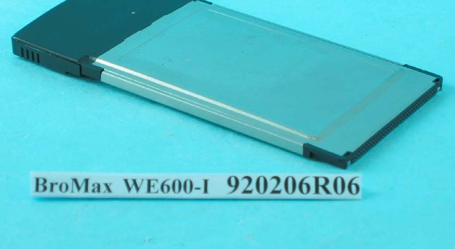
O6M-WE600I
Apr 13, 200354M WLAN Cardbus Adapter
Equipment Class
DTS - Digital Transmission System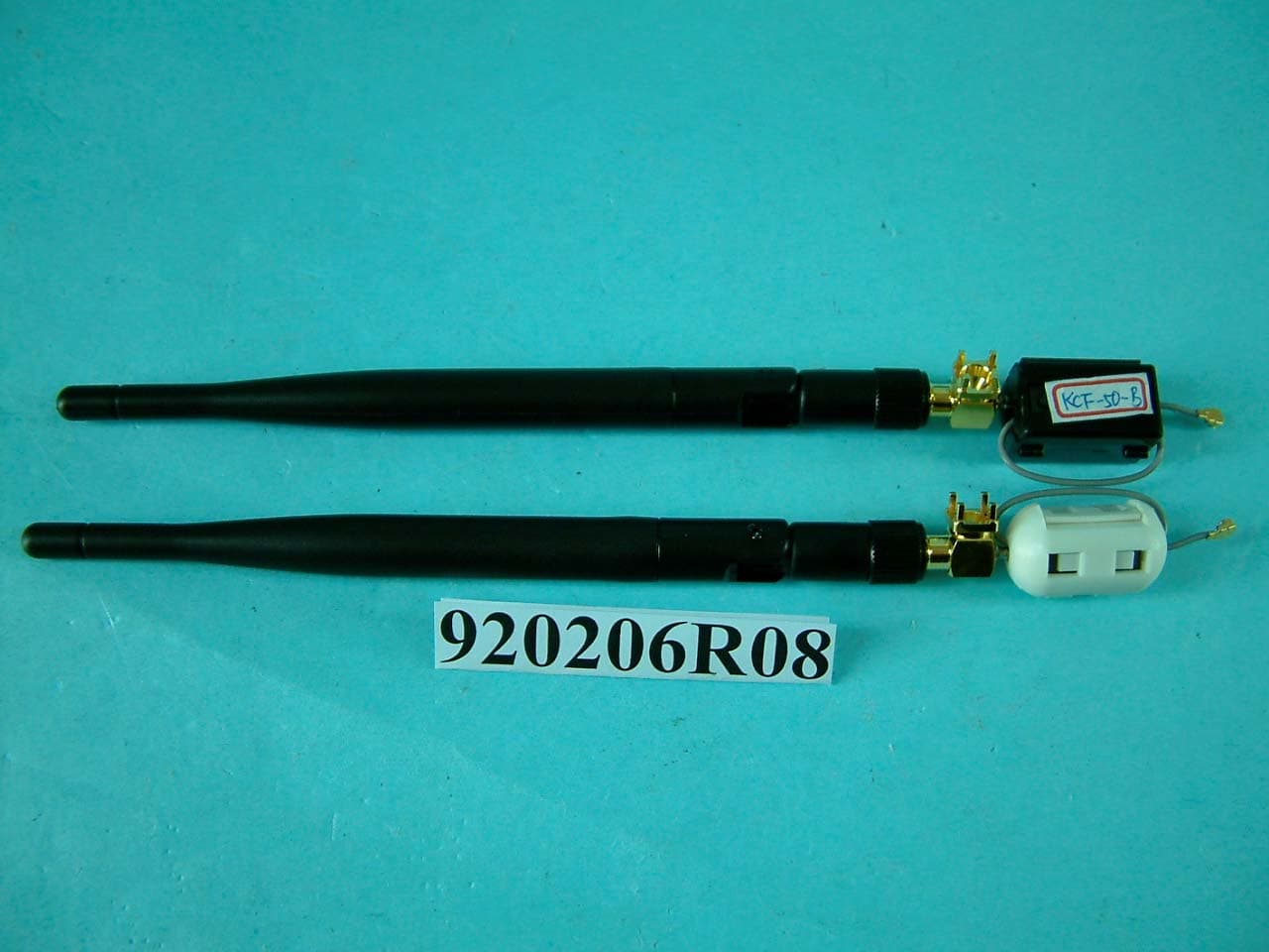
O6M-WM600I
Mar 30, 200354M WLAN Module
Equipment Class
DTS - Digital Transmission System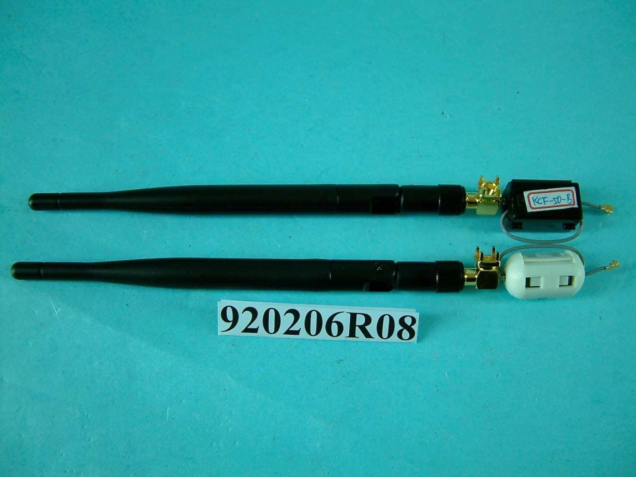
O6M-WM6001
Mar 25, 200354M WLAN Module
Equipment Class
DTS - Digital Transmission System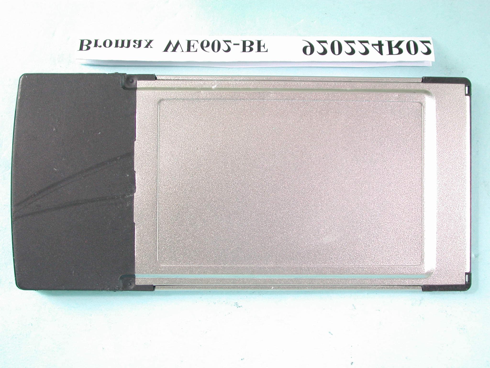
O6M-WE602B
Mar 12, 200354M Wireless LAN CardBus Card
Equipment Class
DTS - Digital Transmission System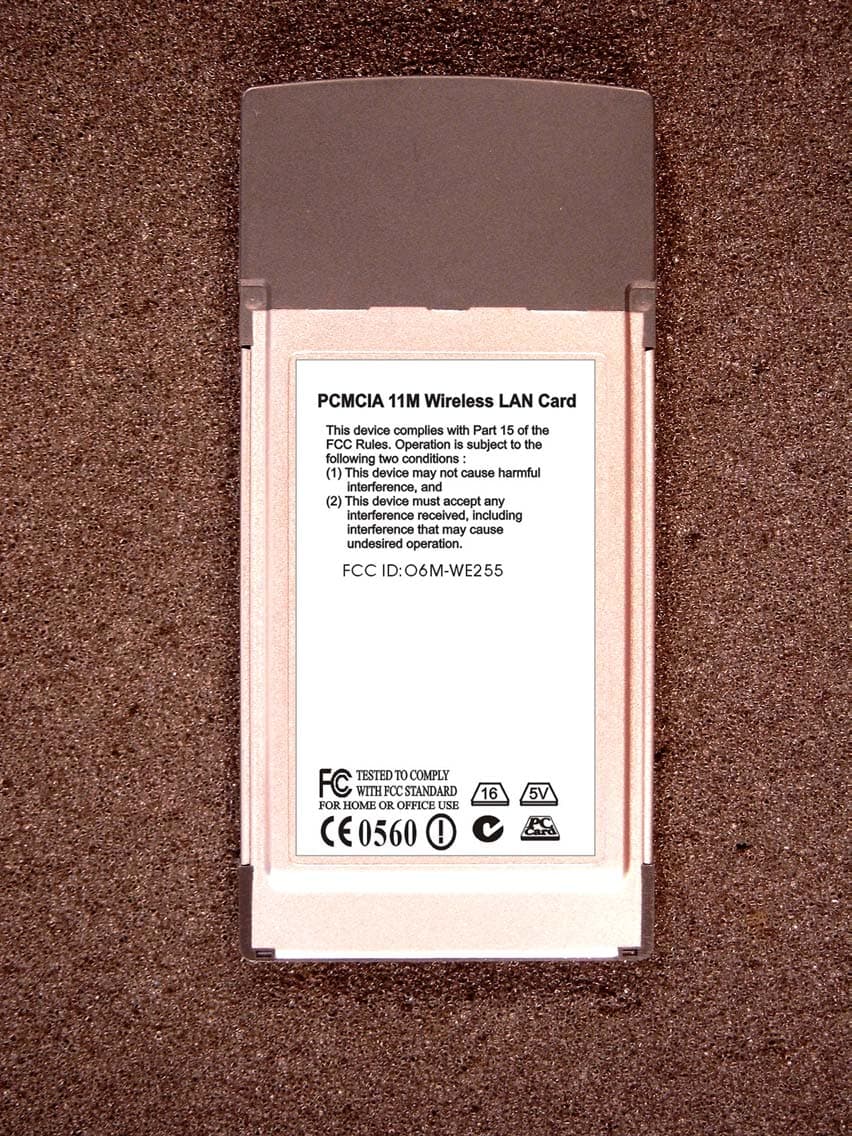
O6M-WE255
Jan 15, 20032.4 GHz WLAN PCMCIA Card
Equipment Class
DTS - Digital Transmission System