O6M-WR251Wireless Print Server
BroMax Communications Inc
Click to zoom
Application Details
- Equipment Class
- DSS - Part 15 Spread Spectrum Transmitter
- Date of Grant
- Aug 11, 2002
- Application Purpose
- Original Equipment
- Date of Application
- Aug 11, 2002
- Equipment Note
- Wireless Print Server
- Frequency Range
- 2412.00000000 - 2462.00000000
- Company
- BroMax Communications Inc
- Country
- Taiwan
Documents & Files
Document Text
Text extracted from the exhibit documents filed with the FCC. Open a document above to read the original.
Users Manual
Wireless Print Server LPV2-WS11GC User’s Manual Using this Manual This section explains the symbols and signs used in this manual. Symbols Caution Items to which you must pay attention when handling the product. Failure to follow this mark may result in personal injury and/or damage to the equipment. Note Supplementary information you should know for handling the product. Reference Refers to a related subject page. • Text in bold indicates the names of menu options, buttons, text boxes, check boxes, software, dialog boxes, etc., that you can select to perform operations. • A personal computer with the BUFFALO Wireless LAN Card installed is called the Wireless LAN PC. • The following terminology is used in this manual to distinguish between an Ethernet 10/100BASE-T LAN and a Wireless LAN. Ethernet LAN: A LAN connected by cables Wireless LAN: A LAN connected by radio signal The preceding terminology is strictly for use in this manual for the sake of convenience and should not be construed as generally accepted terminology outside this context. • The personal computer to be used to change the LPV2-WS11GC settings is referred to as the Setting PC. All rights for this manual are owned by BUFFALO. No part of it may be transmitted, reproduced or revised without expressed permission from BUFFALO. The names of other products used in this manual are trademarks or registered trademarks. Trademark symbols , , are not indicated in this manual. Specifications, designs and other descriptions in this manual are subject to change without notice. This manual has been carefully prepared, however, feel free to contact your nearest sales representative if you have any questions or problems. In addition, please note that BUFFALO. shall not be liable for any expenses incurred due to damage or loss arising from use of the LPV2-WS11GC, even though BUFFALO has been advised of the possibility of such damage. LPV-WL11G User’s Manual (Introduction)3 For your safety, be sure to follow the instructions given below. Follow the instructions below to avoid harming yourself, other people and property, and to ensure safe use of the product. For your, others and property safety be sure to read, understand and follow the instructions given below thoroughly before using the product. This manual contains instructions concerning general operation of the computer to which the product is connected in addition to those concerning the product itself. Please take note that our warranty will not cover any failures and problems of the computer, any losses and failures of data, or failures and problems of the product caused by misuse. Signs and symbols used in this manual Warning signs: Symbols: WARNING The instructions with this sign indicate prohibited actions. Failure to fol- low the instructions shown with this sign may result in death or serious injury to the user. CAUTION Failure to follow the instructions shown with this sign may result in injury to the user or property damage. This indicates warnings and cautions. (Ex. Exercise care to avoid an electric shock.) This indicates prohibiting actions. (Ex. Do not disassemble.) This indicates what must be done. (Ex. Disconnect the plug from the outlet.) WARNING Strongly recommended Follow the warning and caution instructions which are issued by the PC and peripheral manufactures. Prohibit Do not attempt to disassemble or repair the LPV2-WS11GC. This may result in fire or electric shock. Strongly recommended Install this product away from children. Failure to do so may result in injury. LPV-WL11G User’s Manual (Introduction)4 Prohibit Do not handle the equipment with wet hands while the power supply cable is connected to the AC socket. This may result in electric shock. Unplug the power supply If you see smoke or smell strange or hear noise from the device unplug the power. Using the device continuously may result in a short circuit, fire, or electric shock. Con- sult your dealer immediately. Unplug the power supply If the product is dropped or subjected to severe shock, unplug the power. Using the device continuously may result in a short circuit, fire, or electric shock. Con- sult your dealer immediately. Unplug the power supply If liquid or foreign matter enters the equipment, unplug the power. Using the device continuously may result in a short circuit, fire, or electric shock. Con- sult your dealer immediately. Prohibit Do not damage, process, overheat or attempt to repair the power supply cable, as this may result in fire or electric shock. • When installing this product, do not crimp the power supply cable. • Do not place heavy objects on the power supply cable, or pull the cable. • Do not place the power supply cable close to heat sources, or overheat the cable. • When removing the power supply cable, be sure to remove it by holding the plug. • Do not bend the cable too much. • Do not move this product with the power supply cable still connected. • If the power supply cable is damaged, replace it. Strongly recommended Use this product under supervision and guidance of an adult when a small child uses. Strongly recommended Insert the AC adapter into the AC socket firmly. Using this product without the AC adapter firmly inserted may cause a short circuit, overheating, fire or electric shock. Strongly recommended Be sure to use the Power Cable (AC adapter) provided. Using other Power cable (including internal connections) and AC adapter may cause fumes or fire due to incompatible voltage or terminal polarity. LPV-WL11G User’s Manual (Introduction)5 CAUTION Strongly recommended To prevent damage due to the static electricity touch a metal object such as a door handle or metal window before touching the device. Static electricity may result in damage to the equipment. Strongly recommended For usage of the PC and peripheral, refer to the product manual. Strongly recommended Remove the dust from all connectors. Dust may result in failure in performance. Prohibit Do not locate thi…
Text truncated - open the document above for the full version.
Cover Letter(s)
BROMAX COMMUNICATIONS, INC. No.20, Kuang Fu Road, Hsin Chu Industrial Park, Hu Kou,Hsin Chu 303, Taiwan, R.O.C. TEL: +886-03-597-2988*8370 FAX: +886-03-568-3414 [email protected] Inform Letter Dear Customer, According to FCC’s regulation, the following Declaration of Conformity has to be made by a company located in USA. They are: This device has been confirmed to be in compliance with the requirements of ANSI C63.4 & FCC part 15 regulations. The test result has been shown in the ADT test report with number RF910531R05. And this compliance is subject to the following two conditions: (1) This device may not cause harmful interference and, (2) This device must accept any interference received, including interference that may cause undesired operation. This declaration can be a separate sheet and be sure that the following message will be also included in this declaration: 1) Product name, model name and trade name. 2) Company name, and address of the one who is responsible for this declaration. 3) Name, title, telephone and fax number as well as the signature of the contact person. Thanks for your attention.
External Photos
Page 1 ANNEX PHOTOGRAPHS OF EUT Page 2 Page 3
ID Label/Location Info
LABEL LOCATION FOR FCC ID: O6M-WR251
Internal Photos
Page 4 Page 5 Page 6 Page 7 Page 8
Operational Description
FCC ID: O6M-WR251 ADT No.910531R05 Operational Description The transmitter of the EUT (Wireless Print Server) is powered by power adapter. The antenna is Ceramic antenna. There is no antenna connector. Under normal use condition, the user has to keep at least 20cm separation distance between radiator and the body of the user. The other instruction, please have a look at the users manual. DSSS Information This device is Direct Sequence Spread Spectrum, the data is mixed by pseudorandom code which is an orthogonal code. The mixed data is digital modulated by BPSK and QPSK technique depends on the data rates. The CCK coding is applied for increasing the data rate, and also the processing gain will be increased. The bit rates are 1,2,5.5,11Mbps, the symbol rates are 1,1,1.375,1.375Mbps, the chip rates are always 11Mbps. So, the Chip/symbol is 11,11,8 and 8 respectively. Although is higher bit rate, the processing gain is lower than 10, but the CCK coding used in higher bit rate will provide 2.2dB coding gain.
RF Exposure Info
ADT No: 910531R05 1 FCC TEST REPORT REPORT NO.: RF910531R05 MODEL NO.: LPV2-WS11GC ACCORDING: FCC Guidelines for Human Exposure IEEE C95.1 APPLICANT:BROMAX COMMUNICATIONS, INC. ADDRESS: No. 20, Kuang Fu Road, Hsin Chu Industrial Park, Hu Kou, Hsin Chu, Taiwan, R.O.C. ISSUED BY:Advance Data Technology Corporation LAB LOCATION:47 14th Lin, Chiapau Tsun, Linko, Taipei, Taiwan, R.O.C. 0528 ILAC MRA Lab Code: 200102-0 ADT No: 910531R05 2 RF Exposure Measurement 1. Introduction 2.4GHz frequency band is regarded specially as a dangerous band for its heating harmfulness to the human body. That’s why microwave oven is operating in this frequency band. The manufacturer whose product is working in this frequency band is obligatory to prove the harmfulness of his product. In this document, we try to prove the safety of radiation harmfulness to the human body for our product. The limit for Maximum Permissible Exposure (MPE) specified in FCC 1.1310 is followed. The Gain of the antenna used in this product is measured in a Fully Anechoic Chamber (FAC) calibrated for antenna measurement in ADT, and also the maximum total power input to the antenna is measured. Through the Friis transmission formula and the maximum gain of the antenna, we can calculate the distance, away from the product, where the limit of MPE is reached. Although the Friis transmission formula is a far field assumption, the calculated result of that is an over-prediction for near field power density. We will take that as the worst case to specify the safety range. 2. RF Exposure Limit According to FCC 1.1310: The criteria listed in the following table shall be used to evaluate the environmental impact of human exposure to radio-frequency (RF) radiation as specified in 1.1307(b) LIMITS FOR MAXIMUM PERMISSIBLE EXPOSURE (MPE) Frequency Range (MHz) Electric Field Strength (V/m) Magnetic Field Strength (A/m) Power Density (mW/cm 2 ) Average Time (minutes) (A)Limits For Occupational / Control Exposures 300-1500......F/3006 1500-100,000......56 (B)Limits For General Population / Uncontrolled Exposure 300-1500......F/15006 1500-100,000......1.030 F = Frequency in MHz ADT No: 910531R05 3 3. Friis Formula Friis transmission formula : Pd = (Pout*G) / (4*pi*r 2 ) where Pd = power density in mW/cm 2 Pout = output power to antenna in mW G = gain of antenna in linear scale Pi = 3.1416 R = distance between observation point and center of the radiator in cm Pd is the limit of MPE, 1 mW/cm 2 . If we know the maximum Gain of the antenna and the total power input to the antenna, through the calculation, we will know the distance r where the MPE limit is reached. Ref. : David K. Cheng, Field and Wave Electromagnetics, Second Edition, Page 640, Eq. (11-133). 4 EUT Operating condition The software provided by Manufacturer enabled the EUT to transmit and receive data at lowest, middle and highest channel individually. 5 Climate Condition The temperature and related humidity: 18 deg. C and 67 % RH 6. Classification This device is not fixed inside the host equipment, it is connected with host through wire. So it is easy to be re-located in the place where at least 20cm far away from the body of the user. Warning statement to the user for keeping at least 20cm or more separation distance with the antenna should be included in users manual. So, this device is classified as Mobile Device. ADT No: 910531R05 4 7 Test Results 7.1 Antenna Gain The maximum Gain measured in Fully Anechoic Chamber is 0dBi or 1 (numeric). 7.2 Output Power Into Antenna & RF Exposure Distance : CHANNEL CHANNEL FREQUENCY (MHz) OUTPUT POWER TO ANTENNA (mW) MINIMUM ALLOWABLE DISTANCE ( r ) FROM SKIN (Centi-Meter) 1241219.501.25 6243718.621.22 11246216.671.15 The minimum allowable distance is very close to the enclosure of the antenna. So, the user has no need to worry about the harmfulness of radiation. But it is recommended to always keep, at least, 20cm separation distance with the antenna.
Test Report
FCC ID: O6M-WR251 Report No.: RF910531R051Issued: August 7, 2002 FCC TEST REPORT REPORT NO.: RF910531R05 MODEL NO.: LPV2-WS11GC RECEIVED: May 31, 2002 TESTED: June 18 ~ June 28, 2002 APPLICANT: BROMAX COMMUNICATIONS, INC. ADDRESS:No. 20, Kuang Fu Road, Hsin Chu Industrial Park, Hu Kou, Hsin Chu, Taiwan, R.O.C. ISSUED BY: Advance Data Technology Corporation LAB LOCATION: 47 14 th Lin, Chiapau Tsun, Linko, Taipei, Taiwan, R.O.C. This test report consists of 46 pages in total. It may be duplicated completely for legal use with the approval of the applicant. It should not be reproduced except in full, without the written approval of our laboratory. The client should not use it to claim product endorsement by CNLA, NVLAP or any government agencies. The test results in the report only apply to the tested sample. 0528 ILAC MRA Lab Code: 200102-0 FCC ID: O6M-WR251 Report No.: RF910531R052Issued: August 7, 2002 Table of Contents 1CERTIFICATION .................................................................................................................... 4 2SUMMARY OF TEST RESULTS............................................................................................ 5 3GENERAL INFORMATION .................................................................................................... 6 3.1GENERAL DESCRIPTION OF EUT....................................................................................... 6 3.2DESCRIPTION OF TEST MODES......................................................................................... 7 3.3GENERAL DESCRIPTION OF APPLIED STANDARDS........................................................ 7 3.4DESCRIPTION OF SUPPORT UNITS................................................................................... 8 4TEST TYPES AND RESULTS ................................................................................................ 9 4.1CONDUCTED EMISSION MEASUREMENT......................................................................... 9 4.1.1LIMITS OF CONDUCTED EMISSION MEASUREMENT ...................................................... 9 4.1.2TEST INSTRUMENTS ...........................................................................................................9 4.1.3TEST PROCEDURES .......................................................................................................... 10 4.1.4TEST SETUP ....................................................................................................................... 10 4.1.5EUT OPERATING CONDITIONS......................................................................................... 11 4.1.6TEST RESULTS ................................................................................................................... 12 4.2RADIATED EMISSION MEASUREMENT............................................................................ 18 4.2.1LIMITS OF RADIATED EMISSION MEASUREMENT ......................................................... 18 4.2.2TEST INSTRUMENTS ......................................................................................................... 19 4.2.3TEST PROCEDURES .......................................................................................................... 20 4.2.4TEST SETUP ....................................................................................................................... 21 4.2.5EUT OPERATING CONDITIONS......................................................................................... 21 4.2.6TEST RESULTS ................................................................................................................... 22 4.36dB BANDWIDTH MEASUREMENT ................................................................................... 27 4.3.1LIMITS OF 6dB BANDWIDTH MEASUREMENT ................................................................ 27 4.3.2TEST INSTRUMENTS ......................................................................................................... 27 4.3.3TEST PROCEDURE ............................................................................................................28 4.3.4TEST SETUP ....................................................................................................................... 28 4.3.5EUT OPERATING CONDITIONS......................................................................................... 28 4.3.6TEST RESULTS ................................................................................................................... 29 4.4MAXIMUM PEAK OUTPUT POWER ................................................................................... 32 4.4.1LIMITS OF MAXIMUM PEAK OUTPUT POWER MEASUREMENT ................................... 32 4.4.2INSTRUMENTS.................................................................................................................... 32 4.4.3TEST PROCEDURES .......................................................................................................... 33 4.4.4TEST SETUP ....................................................................................................................... 33 4.4.5EUT OPERATING CONDITIONS......................................................................................... 33 4.4.6TEST RESULTS ................................................................................................................... 34 4.5POWER SPECTRAL DENSITY MEASUREMENT.............................................................. 35 4.5.1LIMITS OF POWER SPECTRAL DENSITY MEASUREMENT............................................ 35 4.5.2TEST INSTRUMENTS ......................................................................................................... 35 4.5.3TEST PROCEDURE ............................................................................................................36 4.5.4TEST SETUP ....................................................................................................................... 36…
Text truncated - open the document above for the full version.
Test Setup Photos
FCC ID: O6M-WR251 Report No.: RF910531R0544Issued: August 7, 2002 5 PHOTOGRAPHS OF THE TEST CONFIGURATION CONDUCTED EMISSION TEST FCC ID: O6M-WR251 Report No.: RF910531R0545Issued: August 7, 2002 RADIATED EMISSION TEST
Contact Information
Applicant
Yung-Chao Tang(Director)
Technical Contact
Advance Data Technology CorporationVivi Wang
[email protected]+886 3 327 0910
13-1, lane 19, WenShan 3rd St · Taoyuan · Taiwan
Test Firm
Bureau Veritas CPS (H.K.) Ltd. Taoyuan BranchRichard Chen
Technical Specifications
| # | Rule Parts | Frequency Range | Power Output |
|---|---|---|---|
| 1 | 15C | 2.41 GHz - 2.46 GHz | 20.00 mW |
Other Applications from BroMax Communications Inc
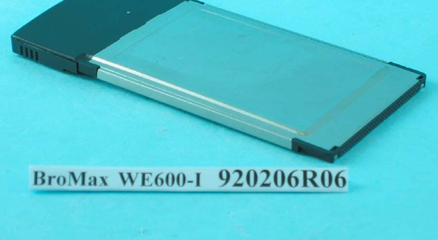
O6M-WE600I
Apr 13, 200354M WLAN Cardbus Adapter
Equipment Class
DTS - Digital Transmission System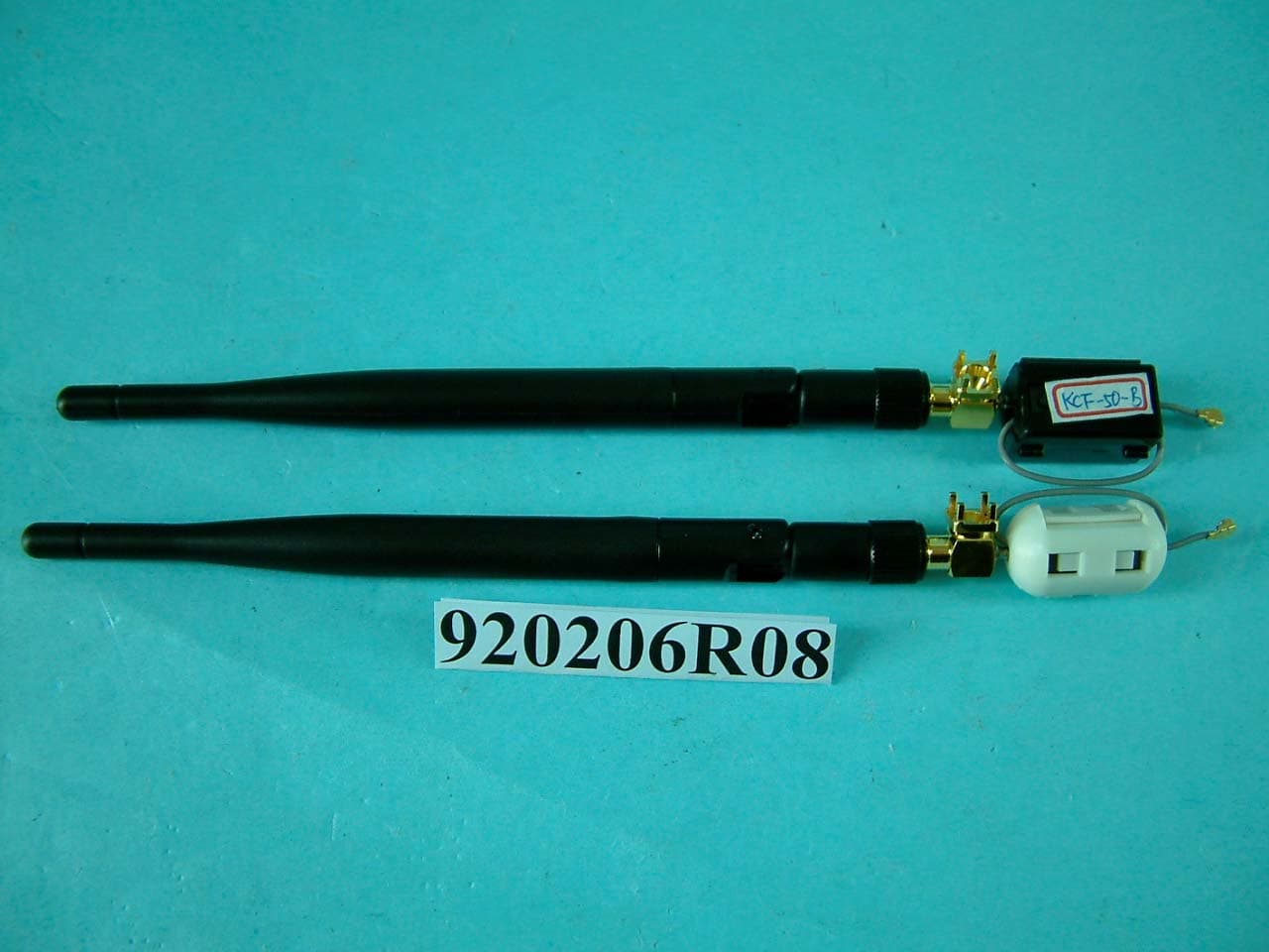
O6M-WM600I
Mar 30, 200354M WLAN Module
Equipment Class
DTS - Digital Transmission System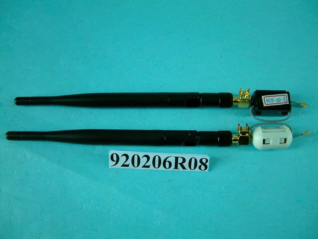
O6M-WM6001
Mar 25, 200354M WLAN Module
Equipment Class
DTS - Digital Transmission System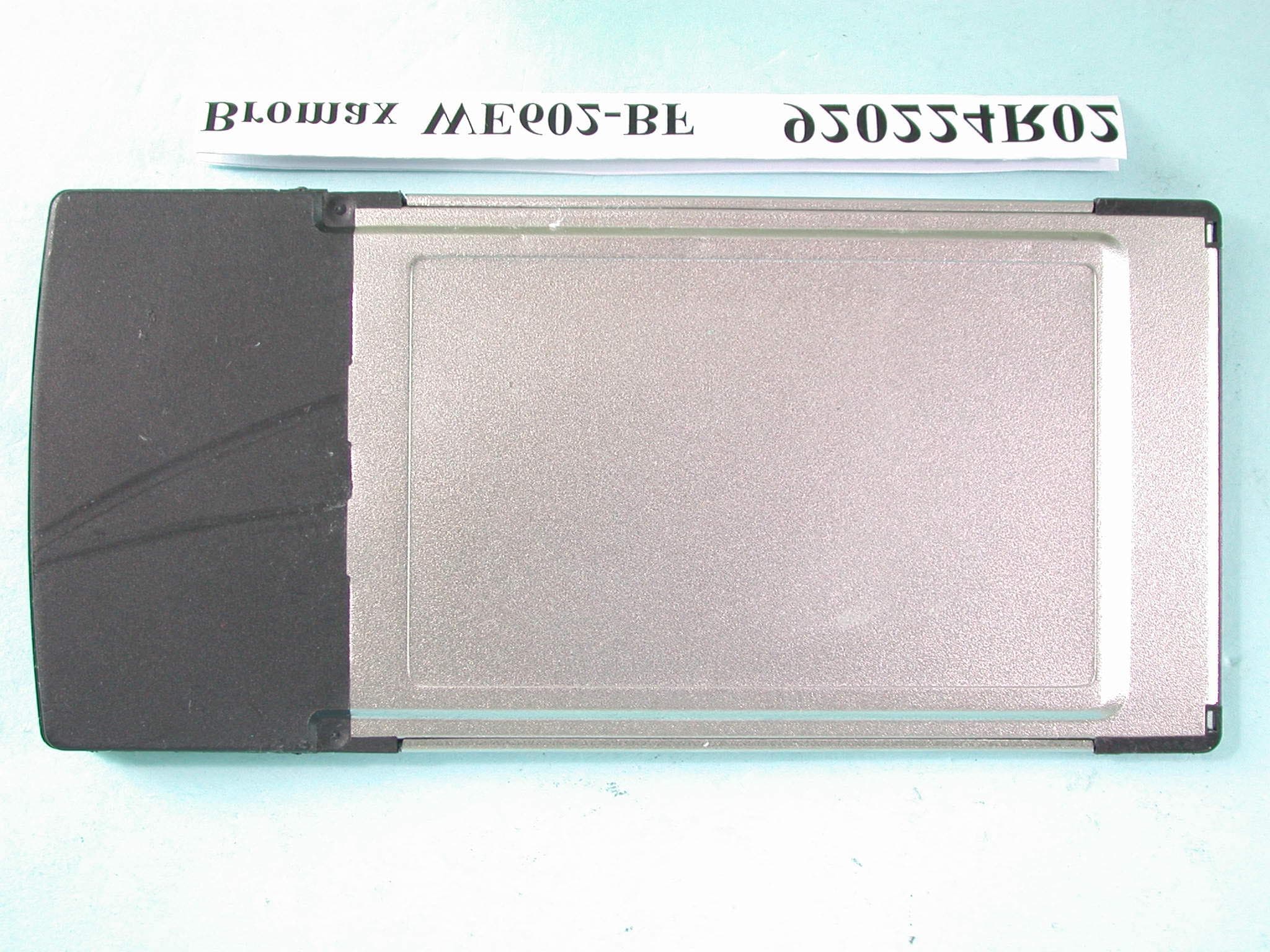
O6M-WE602B
Mar 12, 200354M Wireless LAN CardBus Card
Equipment Class
DTS - Digital Transmission System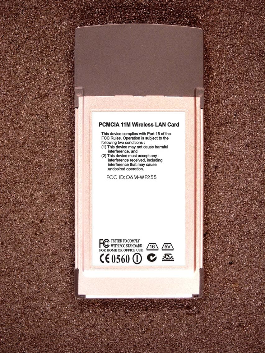
O6M-WE255
Jan 15, 20032.4 GHz WLAN PCMCIA Card
Equipment Class
DTS - Digital Transmission System