O6M-WUSB11Instant Wireless - Network USB Adapter
BroMax Communications Inc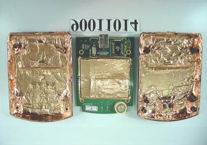
Click to zoom
Application Details
- Equipment Class
- DSS - Part 15 Spread Spectrum Transmitter
- Date of Grant
- Feb 18, 2001
- Application Purpose
- Original Equipment
- Date of Application
- Feb 18, 2001
- Equipment Note
- Instant Wireless - Network USB Adapter
- Frequency Range
- 2412.00000000 - 2462.00000000
- Company
- BroMax Communications Inc
- Country
- Taiwan
Documents & Files
Document Text
Text extracted from the exhibit documents filed with the FCC. Open a document above to read the original.
Users Manual
Instant Wireless - Network USB Adapter User Manual Instant Wireless - Network USB Adapter User Manual 2 Regulatory compliance FCC Warning This equipment has been tested and found to comply with the limits for a Class B digital device, pursuant to part 15 of the FCC Rules. These limits are designed to provide reasonable protection against harmful interference in a residential installation. This equipment generates, uses and can radiate radio frequency energy and, if not installed and used in accordance with the instructions, may cause harmful interference to radio communications. However, there is no guarantee that interference will not occur in a particular installation. If this equipment does cause harmful interference to radio or television reception, which can be determined by turning the equipment off and on, the user is encouraged to try to correct the interference by one or more of the following measures: - Reorient or relocate the receiving antenna. - Increase the separation between the equipment and receiver. - Connect the equipment into an outlet on a circuit different from that to which the receiver is connected. - Consult the dealer or an experienced radio/TV technician for help. You are cautioned that changes or modifications not expressly approved by the party responsible for compliance could void your authority to operate the equipment. FCC Radiation Exposure Statement This equipment complies with FCC radiation exposure limits set forth for an uncontrolled environment. This equipment should be installed and operated with minimum distance 20cm between the radiator & your body. About this manual This user manual describes how to install and operate your Instant Wireless - Network USB Adapter. Please read this manual before you install the product. This manual includes the following topics: - Product description and features. - Hardware installation procedure. - Software installation procedure. - Product Specification Instant Wireless - Network USB Adapter User Manual 3 Table of Contents Section 1 Introduction4 1.1 Package Contents4 1.2 System Requirements4 1.3 Features4 Section 2 Hardware Installation6 2.1 Connecting the USB Adapter6 2.2 Status LEDs6 2.3 Remove the USB Adapter6 Section 3 Installation and Configuration Procedures Under Windows 987 3.1 What You Need to Know About Windows 987 3.2 What You Will Need7 3.3 Installing the Driver Under Windows 987 3.4 Configuration Under Windows 9811 3.5 Uninstall Procedure Under Windows 9812 Section 4 Installation and Configuration Procedures Under Windows 200013 4.1 What You Need to Know About Windows 200013 4.2 What You Will Need13 4.3 Installing the Driver Under Windows 200013 4.4 Configuration Under Windows 200017 4.5 How to Unplug the Device Under Windows 200018 4.6 Uninstall Procedure Under Windows 200019 Section 5 Installation and Configuration Procedures Under Windows ME20 5.1 What You Need to Know About Windows ME20 5.2 What You Will Need20 5.3 Installing the Driver Under Windows ME20 5.4 Configuration Under Windows ME21 5.5 Uninstall Procedure Under Windows ME22 Section 6 Configuration and Monitor Application23 6.1 How to Install the Configuration and Monitor Application23 6.2 Using the Configuration and Monitor Application23 Instant Wireless - Network USB Adapter User Manual 4 6.3 How to Uninstall the Configuration and Monitor Application28 Appendix A Specification29 Instant Wireless - Network USB Adapter User Manual 5 Section 1 - Introduction The Instant Wireless - Network USB Adapter is a network adapter with a rate of 1, 2, 5.5, and 11 Mbps operating in the ISM band using Direct Sequence Spread Spectrum (DSSS) transmission implementing the IEEE 802.11b standard. This adapter provides Device Drivers for MS Windows ® 98, Windows ® 2000 and Windows ® ME. It also provides tools for the configuration and firmware upgrade of the adapter. These tools, as well as the installation steps of the plug-and-play procedure for the Microsoft Windows 98, Windows ME and Windows 2000 operating systems, are described in this document. 1.1 Package Contents Please make sure that items below are included on package. - A Instant Wireless - Network USB Adapter - A USB cables - CD-ROM (include Device Drivers and User Manual) - A Quick Installation Guide 1.2 System Requirements - Operating System: MS Windows 98, Windows 2000, Windows ME - Desktop PC or notebook PC with CD-ROM drive - One free USB port 1.3 Features The Instant Wireless - Network USB Adapter offers compliance with the IEEE 802.11b specification. This feature allows them to communicate with other wireless devices that support the standard. Features of the adapter are: ! Uses 2.4GHz frequency band, which complies with worldwide requirement ! Wireless interface following the IEEE 802.11b standard ! Using Universal Serial Bus (USB) interface ! Enciphering/deciphering of wireless data by the implementation of the WEP algorithm (WEP-40 bits) ! Wire-free access to networked resources from anywhere beyond the desktop ! Allows users move between Access Points without resetting their connection reconfiguration ! Delivers data rate up to 11 Mbps ! Supports 11, 5.5, 2, and 1 Mbps rates Instant Wireless - Network USB Adapter User Manual 6 ! Roaming ! Provide Instant Wireless - Network Configuration utility ! Dielectric Antenna is built in to the Adapter with LEDs indicating Power and Link ! Supports most popular operating systems: Window 98/2000 & Windows ME Instant Wireless - Network USB Adapter User Manual 7 Section 2 - Hardware Installation This chapter covers connecting your Instant Wireless - Network USB Adapter to USB port of desktop or notebook PC, and connecting the Adapter to a network. 2.1 Connecting the USB Adapter Follow the procedure below to install the Adapter. 1. Connect one end of USB cable into the Adapter. 2. Connect the other end of USB cable to USB port on desktop or notebook PC. 2.2 Status LEDs The following table describes the meaning of the LEDs: LEDMEANING PWRIndicates…
Text truncated - open the document above for the full version.
External Photos
Report No.: RF900110141Issued: Feb. 2, 2001 ANNEX PHOTOGRAPHS OF EUT Report No.: RF900110142Issued: Feb. 2, 2001
Internal Photos
Report No.: RF900110142Issued: Feb. 2, 2001 Report No.: RF900110143Issued: Feb. 2, 2001 Report No.: RF900110144Issued: Feb. 2, 2001
Operational Description
FCC ID: O6M-WUSB11 ADT NO. 90011014 Operational Description The transmitter of the EUT (Instant Wireless – Network USB Adapter) is powered by host notebook. The antenna is Ceramic Patch Antenna. Under normal use condition, the device should be placed at least 20 cm far away from the user or nearby person, and it is easy to be relocated. The other instruction, please have a look at the users manual.
Test Report
FCC ID: O6M-WUSB11 Report No.: RF90011014 1 Issued: Feb. 2, 2001 FCC TEST REPORT REPORT NO.: RF90011014 MODEL NO.: WUSB11 RECEIVED: January 10, 2001 TESTED: January 30, 2001 APPLICANT: BroMax Communications, Ink. ADDRESS: No.20, Kuang Fu Rd., Hsin Chu Industrial Park, Hu Kou, Hsinchu, Taiwan, R.O.C. ISSUED BY: Advance Data Technology Corporation LAB LOCATION: 13-1, Lane 19, Wen Shan 3 rd St., Kweishan, Taoyuan Hsien, Taiwan, R.O.C. This test report consists of 68 pages in total. It may be duplicated completely for legal use with the approval of the applicant. It should not be reproduced except in full, without the written approval of our laboratory. The client should not use it to claim product endorsement by NVLAP or any U.S. government agencies. The test results in the report only apply to the tested sample. Accredited Laboratory FCC ID: O6M-WUSB11 Report No.: RF90011014 2 Issued: Feb. 2, 2001 Table of Contents 1CERTIFICATION ..................................................................................................... 4 2SUMMARY OF TEST RESULTS............................................................................ 5 3GENERAL INFORMATION.......................................................................... 6 3.1GENERAL DESCRIPTION OF EUT ............................................................ 6 3.2DESCRIPTION OF TEST MODES .............................................................. 6 3.3GENERAL DESCRIPTION OF APPLIED STANDARDS ............................. 7 3.4DESCRIPTION OF SUPPORT UNITS ........................................................ 7 3.5CONFIGURATION OF SYSTEM UNDER TEST ......................................... 7 4TEST PROCEDURES AND TEST RESULTS ........................................................ 8 4.1CONDUCTED EMISSION MEASUREMENT............................................... 8 4.1.1LIMITS OF CONDUCTED EMISSION MEASUREMENT..................................................... 8 4.1.2TEST INSTRUMENTS ..........................................................................................................8 4.1.3TEST PROCEDURES...........................................................................................................9 4.1.4TEST SETUP ...................................................................................................................... 10 4.1.5TEST RESULTS.................................................................................................................. 11 4.2RADIATED EMISSION MEASUREMENT.................................................. 17 4.2.1LIMITS OF RADIATED EMISSION MEASUREMENT........................................................ 17 4.2.2TEST INSTRUMENTS ........................................................................................................ 18 4.2.3TEST PROCEDURES......................................................................................................... 19 4.2.4TEST SETUP ...................................................................................................................... 20 4.2.5TEST RESULTS.................................................................................................................. 21 4.36dB BANDWIDTH MEASUREMENT ......................................................... 25 4.3.1LIMITS OF 6dB BANDWIDTH MEASUREMENT ............................................................... 25 4.3.2TEST INSTRUMENTS ........................................................................................................ 25 4.3.3TEST PROCEDURE ........................................................................................................... 26 4.3.4TEST SETUP ...................................................................................................................... 26 4.3.5EUT OPERATING CONDITION.......................................................................................... 26 4.3.6TEST RESULTS.................................................................................................................. 27 4.4MAXIMUM PEAK OUTPUT POWER......................................................... 31 4.4.1LIMITS OF MAXIMUM PEAK OUTPUT POWER MEASUREMENT.................................. 31 4.4.2INSTRUMENTS .................................................................................................................. 31 4.4.3TEST PROCEDURES......................................................................................................... 32 4.4.4TEST SETUP ...................................................................................................................... 32 4.4.5EUT OPERATING CONDITION.......................................................................................... 32 4.4.6TEST RESULTS.................................................................................................................. 33 4.5POWER SPECTRAL DENSITY MEASUREMENT .................................... 34 4.5.1LIMITS OF POWER SPECTRAL DENSITY MEASUREMENT .......................................... 34 FCC ID: O6M-WUSB11 Report No.: RF90011014 3 Issued: Feb. 2, 2001 4.5.2TEST INSTRUMENTS ........................................................................................................ 34 4.5.3TEST PROCEDURE ........................................................................................................... 35 4.5.4TEST SETUP ...................................................................................................................... 35 4.5.5EUT OPERATING CONDITION.......................................................................................... 35 4.5.6TEST RESULTS.................................................................................................................. 36 4.6BAND EDGES MEASUREMENT .............................................................. 40 4.6.1LIMITS OF BAND EDGES MEASUREMENT..................................................................... 4…
Text truncated - open the document above for the full version.
Test Report
FCC ID: O6M-WUSB11 Report No.: RF90011014 45 Issued: Feb. 2, 2001 4.7 PROCESSING GAIN OF A DIRECT SEQUENCE SPREAD SPECTRUM MEASUREMENT(WORSE CASE) 4.7.1 LIMITS OF PROCESSING GAIN OF A DIRECT SEQUENCE SPREAD SPECTRUM MEASUREMENT Limit The limit of processing gain is 10dB 4.7.2 TEST INSTRUMENTS & SUPPORT UNIT Description & ManufacturerModel No.Serial No. Hewlett Packard Spectrum Analyzer, 9kHz to 22GHz HP8593ES942848 Marconi Signal Generator, 10kHz to 2.7GHz 2031953426 Hewlett Packard Power Meter,HP438AS952633 Hewlett Packard Power Sensor, -20 to – 70dBm HP8481DSCD15369 Hewlett Packard Attenuator, 6dB to 10 dB HP8493ANA Hewlett Packard Step Attenuator, 1dB ste ps HP8494ANA Hewlett Packard Step Attenuator, 10dB steps HP8495DNA Hewlett Packard Power Splitter,HP11667B04390 Campaq Laptop Computer (Qty 2),Armada 1700NA FCC ID: O6M-WUSB11 Report No.: RF90011014 46 Issued: Feb. 2, 2001 4.7.3 METHOD OF MEASUREMENT The processing gain may be measured using the CW jamming margin method. Figure 1 shows the test configuration. The test consists of stepping a signal generator in 50 kHz increments across the passband of the system. At each point, the generator level required to produce the recommended Bit Error Rate (BER) is recorded. This level is jammer level. The output power of the transmitting unit is measured at the same point. The jammer to Signal (J/S) ratio is then calculated. Discard the worst 20% of the J/S data points. The lowest remaining J/S ratio is used when calculating the Process Gain. The reference PER is specified as 8%. The corresponding Es/No (signal to noise ratio per symbol) is 16.4 dB. The curve is attached as below. This value and the measured J/S ratio are used in the following equation to calculate the Process Gain (Gp) of the system. Where: (S/N) o : Signal to noise ratio for the chosen BER. Mj : Maximum jammer to Signal Ratio recorded at the detected BER. Gp = (S/N) o +Mj+Lsys FCC ID: O6M-WUSB11 Report No.: RF90011014 47 Issued: Feb. 2, 2001 Lsys : System losses . For the purpose of this processing gain calculation, we assume Lsys at its minimum value of 2 dB. Applicable Reference Documents. “HFA3861A Direct Sequence Spread Spectrum Baseband Processor” Harris Corporation Semiconductor Sector Preliminary Data Sheet, Melbourne FL, July 1999. “M-ary Orthogonal Keying BER Curve”. 4.7.4 TEST SETUP Transmitter HP11667B Power Splitter HP8493A HP8494A STEP ATTN 11dB (1dB steps) HP8495D HP8493A STEP ATTN 70dB (10dB steps) HP11667B Power Splitter HP8493A Receiver Matched Cables For the actual test configuration, please refer to the related Item – Photographs of the Test Configuration. Laptop Compaq Computer Armada 1700 PCMCIA CARD WL11000-1 10 dB MARCONI 2031 SIGNAL GENERATOR 6dB 10dB PCMCIA CARD Laptop Compaq Computer Armada 1700 PWR SENSOR HP 8481D Power meter HP 438A FCC ID: O6M-WUSB11 Report No.: RF90011014 48 Issued: Feb. 2, 2001 4.7.5 TEST PROCEDURES Obtain the simplex link shown. Perform all independent instrumentation calibrations prior to this procedure. Set operating power levels using fixed and variable attenuators in system to meet the following objectives: Signal Power at receiver approximately –60dBm (above thermal sensitivity such that thermal noise does not cause bit errors. Signal Power at power meter between –20 and –30dBm for optimal linearity. Use spectrum analyzer to monitor test. Ensure that CW Jammer generator RF output is disabled and measure the power at the power meter port using the power meter. This is the relative signal power, Sr. Disable Transmitter, and set CW Jammer generator RF output frequency equal to the carrier frequency and enable generator output. Set reference CW Jammer power level at power meter port 8.4dB below Sr (minimum J/S, or 10dB processing gain reference level). Note the power level setting on the generator, this is the reference CW Jammer power setting, Jr. Disable CW Jammer, re-establish link. PER test should be operating essentially error -free. Enable CW Jammer at the reference power level and verify that the PER test indicates a PER of less than 8%. Alternatively, adjust the CW Jammer level to that which causes 8% PER and verify that the S/J is less than 8.4dB. Repeat step 7 for uniform steps in frequency increments of 50 kHz across the receiver passband with the CW Jammer. In this case the receiver passband is +/- 8.5 MHz. The numerical data associated with the following radio channel is tabulated and presented for : CHANNEL 1 .................................................................................................. . Channel 6: 2437 MHz Channel 11 : 2462 MHz 4.7.6 EUT OPERATING CONDITION The software provided by client to set the EUT to transmit at lowest, middle and highest channel. FCC ID: O6M-WUSB11 Report No.: RF90011014 49 Issued: Feb. 2, 2001 4.7.7 TEST RESULTS EUTInstant Wireless-Network USB AdapterModel WUSB11 Environmental Conditions 20°C, 60RHTe s t e d B ySteven Lu Although the theoretical processing gain is lower than 10 dB, but the CCK coding provides an extra coding gain of 2.2dB. 11Mbps CHANNEL 1 Processing Gain Gp = (S/N)。 。。 。+ Mj + Lsys Freq.Gp (S/N)。 。。 。 Mj = J/SLsysJammerLVL (GHz)(dB)(dB)(dB)(dB)(dBm)(dBm) 2.409511.316.4-7.12-47.1-0.7 2.4095511.416.4 -72-47-0.6 2.409611.416.4-72-47-0.6 2.4096511.416.4-72-47-0.6 2.409711.316.4-7.12-47.1-0.7 2.4097511.316.4-7.12-47.1-0.7 2.409811.116.4-7.32-47.3-0.9 2.4098511.116.4-7.32-47.30.9 2.40991116.4-7.42-47.4-1 2.409951116.4-7.42-47.4-1 2.4110.916.4-7.52-47.5-1.1 2.410051116.4-7.42-47.4-1 2.41011116.4-7.42-47.4-1 2.4101511.116.4-7.32-47.3-0.9 2.410211.216.4-7.22-47.2-0.8 2.4102511.316.4-7.12-47.1-0.7 2.410311.316.4-7.12-47.1-0.7 2.4103511.416.4-72-47-0.6 2.410411.316.4-7.12-47.1-0.7 2.4104511.316.4-7.12-47.1-0.7 2.410511.316.4-7.12-47.1-0.7 2.4105511.216.4-7.22-47.2-0.8 2.410611.216.4-7.22-47.2-0.8 2.4106511.316.4-7.12-47.1-0.7 2.410711.316.4-7.12-47.1-0.7 2.4107511.316.4-7.12-47.1-0.7 2.410811.416.4-72-47-0.6 2.4108511.516.4-6.92-46.9-0.5 2.410911.616.4-6.82-…
Text truncated - open the document above for the full version.
Test Report
This device is Direct Sequence Spread Spectrum, the data is mixed by pseudorandom code which is an orthogonal code. The mixed data is digital modulated by BPSK and QPSK technique depends on the data rates. The CCK coding is applied for increasing the data rate, and also the processing gain will be increased. The bit rates are 1, 2, 5.5, 11 Mbps, the symbol rates are 1, 1, 1.375, 1.375 Mbps, the chip rates are always 11Mbps. So, the Chip/symbol is 11, 11, 8 and 8 respectively. Although in higher bit rate, the processing gain is lower than 10, but the CCK coding used in higher bit rate will provide 2.2dB coding gain.
Test Setup Photos
FCC ID: O6M-WUSB11 Report No.: RF90011014 66 Issued: Feb. 2, 2001 5 PHOTOGRAPHS OF THE TEST CONFIGURATION CONDUCTED EMISSION TEST FCC ID: O6M-WUSB11 Report No.: RF90011014 67 Issued: Feb. 2, 2001 RADIATED EMISSION TEST
Contact Information
Applicant
Yung-Chao Tang(Director)
Test Firm
Bureau Veritas CPS (H.K.) Ltd. Taoyuan BranchTommy Wu
Technical Specifications
| # | Rule Parts | Frequency Range | Power Output |
|---|---|---|---|
| 1 | 15C | 2.41 GHz - 2.46 GHz | 56.00 mW |
Other Applications from BroMax Communications Inc
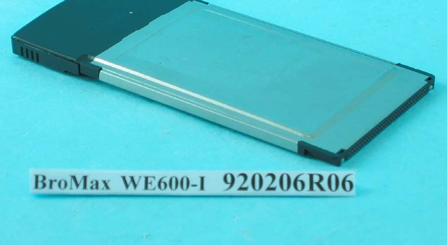
O6M-WE600I
Apr 13, 200354M WLAN Cardbus Adapter
Equipment Class
DTS - Digital Transmission System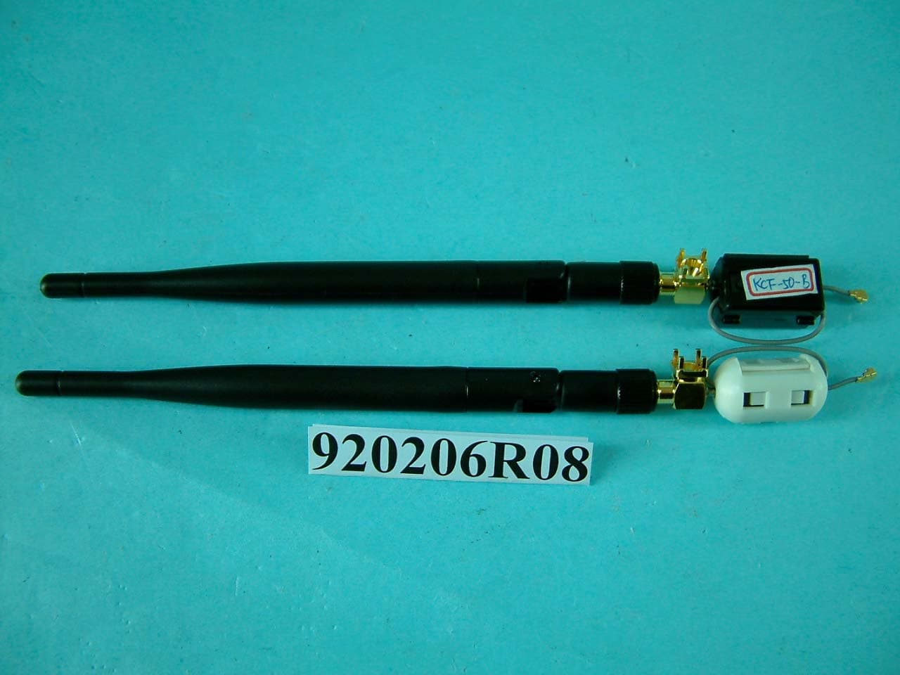
O6M-WM600I
Mar 30, 200354M WLAN Module
Equipment Class
DTS - Digital Transmission System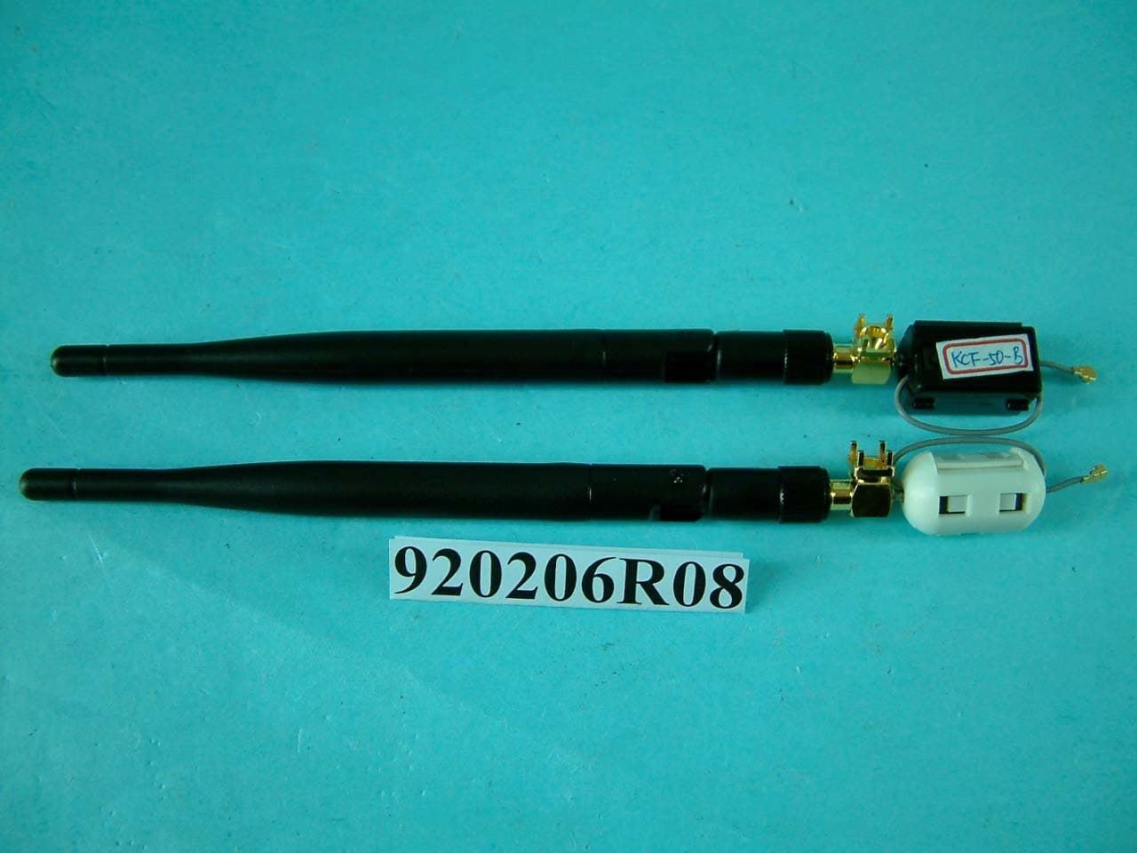
O6M-WM6001
Mar 25, 200354M WLAN Module
Equipment Class
DTS - Digital Transmission System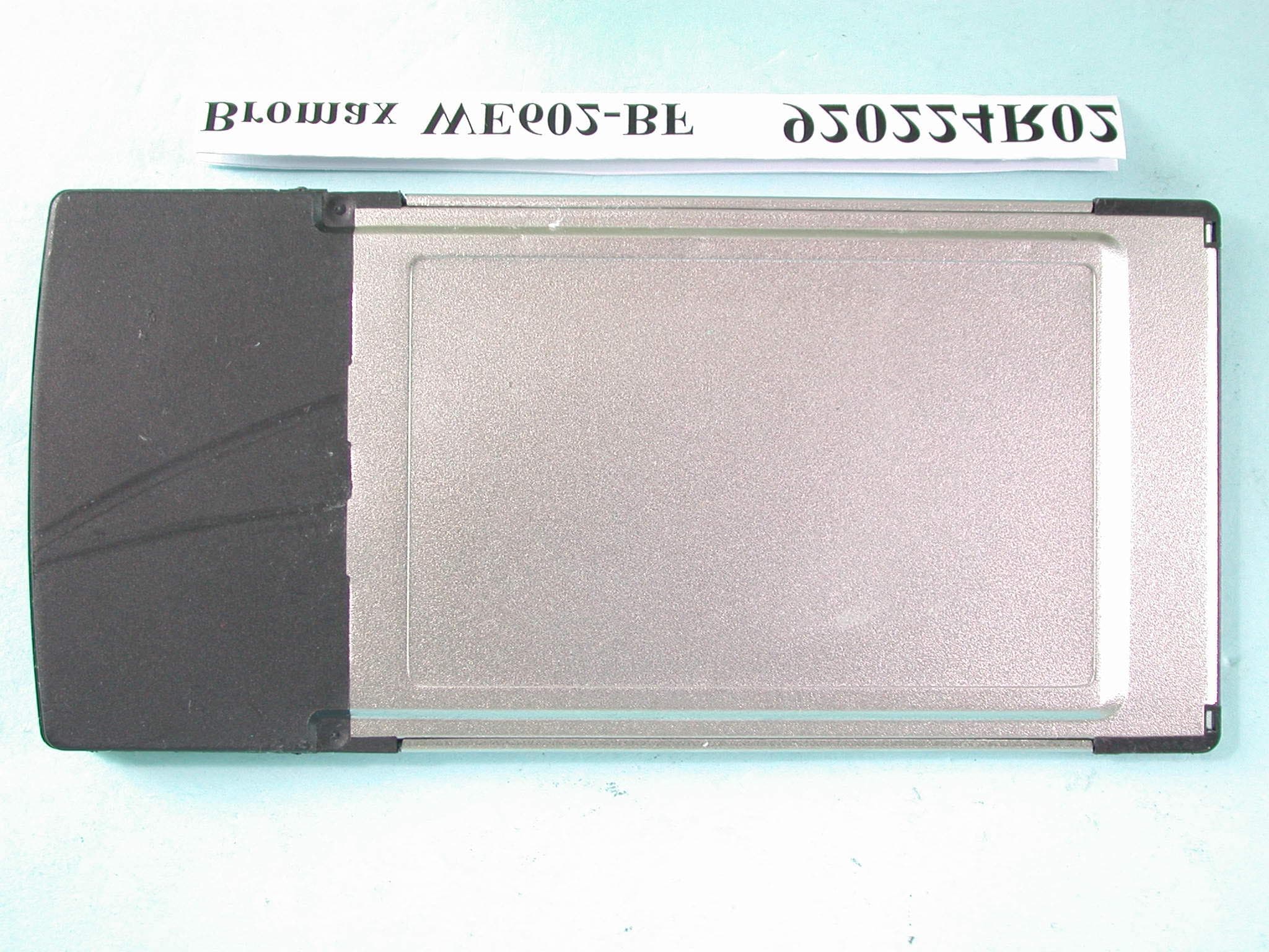
O6M-WE602B
Mar 12, 200354M Wireless LAN CardBus Card
Equipment Class
DTS - Digital Transmission System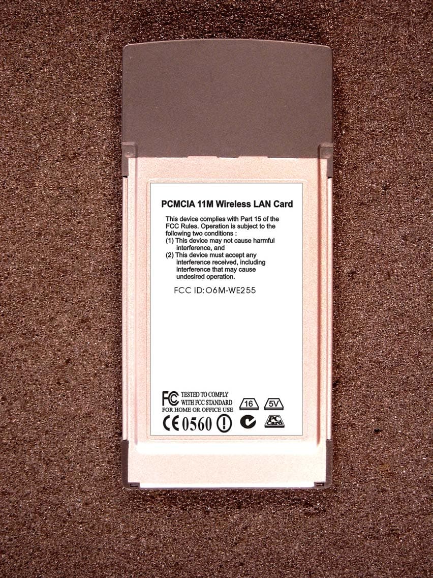
O6M-WE255
Jan 15, 20032.4 GHz WLAN PCMCIA Card
Equipment Class
DTS - Digital Transmission System