O7B-BIRDDETER-245Bird deterrent device activator
BirdDeter Pty. Ltd.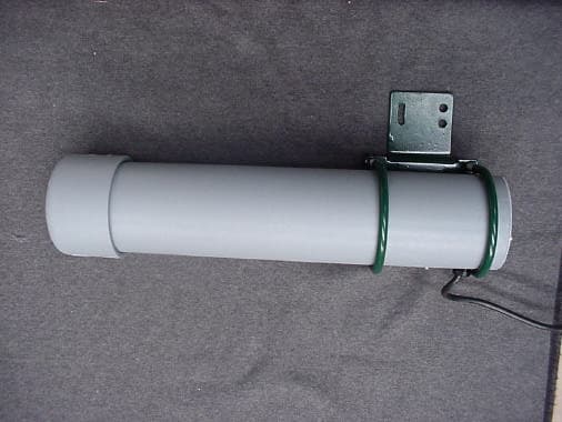
Click to zoom
Application Details
- Equipment Class
- DXX - Part 15 Low Power Communication Device Transmitter
- Date of Grant
- Mar 11, 2001
- Application Purpose
- Original Equipment
- Date of Application
- Mar 11, 2001
- Equipment Note
- Bird deterrent device activator
- Frequency Range
- 2435.00000000 - 2465.00000000
- Company
- BirdDeter Pty. Ltd.
- Country
- Australia
Documents & Files
Document Text
Text extracted from the exhibit documents filed with the FCC. Open a document above to read the original.
Users Manual
MAN—BD 3.3 August 1999 Copyright BirdDeter Pty Ltd Australia BirdDeter Radar-activated systems User Manual BirdDeter Pty Ltd A.C.N. 081 062 482 PO Box 1056 Warwick Queensland 4370 Australia (Deliveries: 53 Victoria Street Warwick Qld 4370) Tel (07) 4667 0491 Fax (07) 4667 0493 MAN—BD 3.3 August 1999 Copyright BirdDeter Pty Ltd Australia “Thank you for choosing BirdDeter’s pest control program!” Please read this page This User Manual has been compiled to save you time and to help you get the best possible results. It is based on years of practical experience with the BirdDeter program and we therefore strongly recommend that you take the time to at least browse through it before you set up your system! BirdDeter Customer Support Our company is dedicated to customer service. We provide a full range of consulting services and our experienced staff are happy to advise on the selection, installation, deployment and commissioning of BirdDeter systems. If urgently needed, our Customer Services Manager, Gavin Lake, can be contacted after hours at 0407 150 227. You can obtain comprehensive technical support by contacting John Muehlebach, our Technical Manager, at the Customer Hotline numbers shown below, between 8.30 am and 5.30 pm, Monday to Friday. Your request for technical assistance will be serviced within 24 hours. Customer Hotlines Tel (650) 610-7900 Fax (650) 593-0118 * * * MAN—BD 3.3 August 1999 Copyright BirdDeter Pty Ltd Australia 1 Contents 1 INTRODUCTION A Unique Approach to Pest Control 2 2 HOW THE SYSTEM WORKS Overview 3 Why use radar? 4 Radar at work 4 False alarms minimised 5 VHF radio link 5 Expanding the system 5 Deterrent System 6 3 SETTING UP IN YOUR CROP Strategy saves on equipment 7 Where and when to install 7 Tricks of the trade 7 An example from the field 8 Installation Precautions 8 4 SYSTEM COMPONENTS E1 - Series 2000 Radar transmitter and control unit 9 E1 - Series 3000 Radar transmitter and control unit 9 E2 – Radar Receiver unit with inbuilt VHF radio transmitter 10 E3 – Deterrent Module with inbuilt VHF radio receiver 10 Optional Electric Hawk 11 Key to System Components 11 Fully Optioned System (illustration) 12 E3 - Deterrent Module Control Box (illustration) 13 5 PARTS LIST E1 – Radar Transmitter 14 E2 – Radar Receiver 15 E3 – Deterrent Module 16 Optional Equipment 16 Electric Hawk 16 Strobe lights 17 Items to be supplied by you 17 Notes 17 6 UNPACKING AND ASSEMBLY Introduction 18 How to erect pole-mounted components 18 E1 – Radar Transmitter 21 E2 – Radar Receiver 23 E3 – Deterrent Module 24 Electric Hawk 25 How to erect complete assemblies on poles 26 Battery connection 29 7 PACKING COMPONENTS FOR STORAGE OR RETURN E1 – Radar Transmitter 30 E2 – Radar Receiver 31 E3 – Deterrent Module 32 8 SOLVING TECHNICAL PROBLEMS Check the system daily 34 Radar Transmitter 34 Radar Receiver 34 False Alarms 35 Sensitivity Adjustment 36 VHF Radio Link 36 Deterrent Module 36 System test 37 Speakers not operating 37 9 FCC COMPLIANCE STATEMENT 38 MAN—BD 3.3 August 1999 Copyright BirdDeter Pty Ltd Australia 2 INTRODUCTION 1 A Unique Approach to Pest Control Your BirdDeter equipment is part of a unique control program for managing pest birds and flying foxes. The BirdDeter control program consists of using the world’s most advanced bird control technology combined with strategic know-how. The equipment incorporates the latest breakthroughs in detection and deterrent technologies. Of course to produce the best results possible, the equipment has to be properly set up. This means it must be deployed strategically and, importantly, at the right time. BirdDeter advisers have gained this deployment know-how over years of fine-tuning the total program in a very wide range of situations. We should emphasise one particular point. The BirdDeter program is totally different to traditional pest control techniques such as scarecrows and noisemakers. Many growers with experience of bird or bat problems recognise that the main shortcoming of these methods is that pests commonly become accustomed to them: in other words, they habituate. Once this occurs, these techniques become ineffective. In contrast, the BirdDeter program keeps on working because it solves the habituation problem. How? By ensuring the pests are exposed to the deterrents only when they will have the greatest impact. This is why the system has been designed so that it is actually switched on by the pests themselves. BirdDeter’s method of deterring pests has two steps: firstly, detection using radar which is set up in a carefully selected area; and secondly, deterrence: scaring the pests away using their own alarm and distress calls, together with calls of predators. Visual deterrents can also be added if needed. The radar detection system is very sophisticated and ‘ignores’ slow- moving objects such as branches of trees. This feature ensures that inappropriate triggering or ‘false alarms’ is kept to the minimum. Pests soon learn that flying into the protected area causes them distress and repeated stressful experiences train them to avoid such an area completely. This unique approach is far more effective than continuous, random or repetitious techniques for scaring birds or flying foxes because it delivers the scaring message with optimal timing. In summary, BirdDeter radar-activated systems offer these unique features: 1 Deterrent system activated by radar 2 Computer controlled deterrents 3 Digital recordings of natural bird or fruit bat calls 4 VHF radio link 5 Habituation prevented 6 Solar power standard 7 Minimal noise pollution 8 Easily transportable 9 Low maintenance MAN—BD 3.3 August 1999 Copyright BirdDeter Pty Ltd Australia 3 HOW THE SYSTEM WORKS 2 Overview A standard BirdDeter system consists of three separate components: a radar transmitter, a radar receiver and one deterrent module. These components are each powered by twelve- volt battery and solar panel. The deterrent module can deliver up to 120 watts of audio po…
Text truncated - open the document above for the full version.
Cover Letter(s)
Federal Communication Commission Equipment Authorization Division Application Processing Branch 7435 Oakland Mills Road Columbia, MD 21045 Reference:FCC ID: 07B-BIRDDETER-245 Subject:Request for confidentiality for FCC Certification Application – BirdDeter Pty Ltd 2.45 GHz Transmitter Pursuant to Rule 47 CFR, Chapter 1, Section 0.459, BirdDeter Pty Ltd, requests that the following detailed technical data regarding the BirdDeter 2.45 GHz Transmitter, be classified and deemed confidential by the Federal Communications Commission (FCC) and as such be withheld from public inspection. Pursuant to 47 CFR, Chapter 1, Section 0.457, the exhibits contain details of trade secrets and technical data that is not made available to competitors and the general public. This information is treated in a confidential manner by BirdDeter Pty Ltd. and guarded from disclosure to our competitors. The exhibits outlined are not routinely made available to BirdDeter Pty Ltd staff, with such access granted only to those specifically involved with this particular project. All employees have signed confidentiality agreements and treat all such documentation in a confidential manner. The manufacture of this product has taken place after an extensive research and development process that has seen the company invest a considerable amount of time and money. The time and effort taken has enabled the product to meet the specific demands of the competitive market for which it is intended and it would be therefore detrimental to allow our competitors easy access to our design and development details. Apart from a limited number of employees, the information has previously only been disclosed to the Test House responsible for conducting testing and authorized to act as our agent during the Certification process. This company was also obliged to sign a confidentiality agreement attesting that all information provided to them for the submission would remain confidential. The following information submitted as part of the FCC certification process should be held confidential: Exhibit - PCB Layouts47 CFR 2.1033(c)10 Complete technical PCB Layouts Exhibit – Schematics47 CFR 2.1033(c)10 Complete technical schematic circuit diagrams Tel: 07 4667 0491 Fax: 07 4667 0493 email:[email protected] PO Box 1056 Warwick Qld 4370 BirdDeter Pty Ltd CAN 081 062 482 Page 2 of 2 BirdDeter Pty Ltd CAN 081 062 482 PO Box 1056 Warwick Qld 4370 Tel: 07 4667 0491 Fax: 07 4667 0493 email:[email protected] Exhibit – Block Diagram47 CFR 2.1033 Detailed technical RF block diagram Exhibit – Photographs47 CFR 2.1033 Internal photographs Sincerely Yours, John Muehlebach Technical Director BirdDeter Pty Ltd
Cover Letter(s)
To: Curtis-Straus LLC From: Chris Zombolas Attn: Barry Quinlan Date: March 13, 2001 Pages: 2 and 3 attachments Re: Product Certification Application EMC Ref: M001204 –Tx FCC ID: O7B-BIRDDETER-245 Dear Barry, Please find following our response to the outstanding issues: 1. Agency /agreement letter – At present we are waiting for manufacturer to forward this to us. 2. Label depicting FCC Logo – Refer to attachment for new label artwork 3. Details of the label material and adhesive - Waiting for information from the manufacturer. 4. Labelling position - The manufacturer has confirmed that the label is affixed to the PVC tube, not the mounting bracket. Previously submitted artwork depicted a label on the bracket – this was in fact a serial number that has now been removed from this position. 5. RF Module Block Diagram - Waiting for diagram from the manufacturer 6. User manual caution statement - Refer attachment for Modified user manual containing required caution statement 7. Battery - We confirm that a fully charged, high capacity battery was used for the test. 8. The emissions were maximised by scanning the antenna and by moving the EUT. 9. Bandwidth of fundamental emission -Refer to graph attached 10. Peak measurement data - Refer to following table. This table is derived from Table 1 in the report, but now includes peak measurement data Peak Level dBμμV/m Average Level dBμμV/m Frequency MHz RBW 1 MHz VBW 1 MHz Limit @ 3m dBμμV/m RBW 1 MHz *VBW 1.6Hz Limit @ 3m dBμμV/m 2444.35 113.5 134 102.8 114 4888.70 62.4 74 50.7 54 7333.05 58.4 74 49.3 54 9777.40 44.1 74 35.8 54 5 – 10 th Harmonics < 40 74 < 35 54 *HP8593EM Average Detector EMC Technologies Pty Ltd A.C.N. 057 105 549 57 Assembly Drive Tullamarine Victoria Australia 3043 Ph: + 613 9335 3333 Fax: + 613 9338 9260 email: [email protected] 11. Bandwidths used for measurments RBW 1MHz VBW 1.6 Hz RBW 1MHz VBW 1MHz 12. Please note inclusion of additional antenna used during testing (Refer to Appendix A, EMCO 3116 Horn Antenna). Best Regards Chris Zombolas Average Measurements Peak measurements
Cover Letter(s)
Page 1 of 2 3/15/01 Barry C. Quinlan From:"Jon D. Curtis" <[email protected]> To:<[email protected]> Sent:Friday, December 22, 2000 8:31 AM Subject:O7B-BIRDDETER245 Dear Mr. Zombolas, Barry Quinlan, Certification Manager, is on holiday and I, Jon Curtis, am filling in. Thank you for your business. We have completed the review of the application for the O7B-BIRDDETER245 and have the following issues to resolve in order to issue the grant. 1. Please supply the agency letter/agreement between the applicant and EMC Technologies. This is required because you are signing the 731 form as an agent on behalf of BirdDeter. 2. The label includes the FCC logo. This logo is not permitted to be used for a certified product. It is used on products subject to Declaration of Conformity. Please supply new label artwork. 3. Please supply details of the label material. Provide the label material (mylar, etc.) and describe the adhesive. We need to verify that it "will last the expected lifetime of the product." 4. Please confirm the label is affixed to the PVC tube and not the mounting bracket. 5. Please supply a block diagram for the RF module. 6. The user guide does not contain the caution statement as required by Part 15.21. Please supply a modified manual with the caution statement.. 7. Please confirm a new battery was used during the testing per 15.31(e). 8. Please confirm the product position was adjusted to maximize emissions. 9. Please supply a bandwidth plot of the fundamental emission. 10. Please supply a time based plot documenting the claimed 50% duty cycle of the transmitter. Alternately, provide peak measurement data for the fundamental and harmonics to demonstrate compliance with the 15.35(b) 20 dB peak emission limits. Page 2 of 2 3/15/01 11. Please tell us the bandwidths (RBW and VBW) used for the measurements. Sincerely, -- Jon D. Curtis, P.E. Director of Engineering Curtis-Straus LLC TCB 527 Great Road Littleton, MA 01460 USA Voice 978-486-8880 Fax 978-486-8828 email: [email protected] WWW.CURTIS-STRAUS.COM
External Photos
FCC ID: O7B-BIRDDETER-245 Report No. M001204-Tx APPENDIX C1 EXTERNAL PHOTOGRAPHS OF TEST SAMPLE FCC ID: O7B-BIRDDETER-245 Report No. M001204-Tx APPENDIX C2 EXTERNAL PHOTOGRAPHS OF TEST SAMPLE
Operational Description
MAN—BD 3.3 August 1999 Copyright BirdDeter Pty Ltd Australia BirdDeter Radar-activated systems User Manual BirdDeter Pty Ltd A.C.N. 081 062 482 PO Box 1056 Warwick Queensland 4370 Australia (Deliveries: 53 Victoria Street Warwick Qld 4370) Tel (07) 4667 0491 Fax (07) 4667 0493 MAN—BD 3.3 August 1999 Copyright BirdDeter Pty Ltd Australia “Thank you for choosing BirdDeter’s pest control program!” Please read this page This User Manual has been compiled to save you time and to help you get the best possible results. It is based on years of practical experience with the BirdDeter program and we therefore strongly recommend that you take the time to at least browse through it before you set up your system! BirdDeter Customer Support Our company is dedicated to customer service. We provide a full range of consulting services and our experienced staff are happy to advise on the selection, installation, deployment and commissioning of BirdDeter systems. If urgently needed, our Customer Services Manager, Gavin Lake, can be contacted after hours at 0407 150 227. You can obtain comprehensive technical support by contacting John Muehlebach, our Technical Manager, at the Customer Hotline numbers shown below, between 8.30 am and 5.30 pm, Monday to Friday. Your request for technical assistance will be serviced within 24 hours. Customer Hotlines Tel (650) 610-7900 Fax (650) 593-0118 * * * MAN—BD 3.3 August 1999 Copyright BirdDeter Pty Ltd Australia 1 Contents 1 INTRODUCTION A Unique Approach to Pest Control 2 2 HOW THE SYSTEM WORKS Overview 3 Why use radar? 4 Radar at work 4 False alarms minimised 5 VHF radio link 5 Expanding the system 5 Deterrent System 6 3 SETTING UP IN YOUR CROP Strategy saves on equipment 7 Where and when to install 7 Tricks of the trade 7 An example from the field 8 Installation Precautions 8 4 SYSTEM COMPONENTS E1 - Series 2000 Radar transmitter and control unit 9 E1 - Series 3000 Radar transmitter and control unit 9 E2 – Radar Receiver unit with inbuilt VHF radio transmitter 10 E3 – Deterrent Module with inbuilt VHF radio receiver 10 Optional Electric Hawk 11 Key to System Components 11 Fully Optioned System (illustration) 12 E3 - Deterrent Module Control Box (illustration) 13 5 PARTS LIST E1 – Radar Transmitter 14 E2 – Radar Receiver 15 E3 – Deterrent Module 16 Optional Equipment 16 Electric Hawk 16 Strobe lights 17 Items to be supplied by you 17 Notes 17 6 UNPACKING AND ASSEMBLY Introduction 18 How to erect pole-mounted components 18 E1 – Radar Transmitter 21 E2 – Radar Receiver 23 E3 – Deterrent Module 24 Electric Hawk 25 How to erect complete assemblies on poles 26 Battery connection 29 7 PACKING COMPONENTS FOR STORAGE OR RETURN E1 – Radar Transmitter 30 E2 – Radar Receiver 31 E3 – Deterrent Module 32 8 SOLVING TECHNICAL PROBLEMS Check the system daily 34 Radar Transmitter 34 Radar Receiver 34 False Alarms 35 Sensitivity Adjustment 36 VHF Radio Link 36 Deterrent Module 36 System test 37 Speakers not operating 37 9 FCC COMPLIANCE STATEMENT 38 MAN—BD 3.3 August 1999 Copyright BirdDeter Pty Ltd Australia 2 INTRODUCTION 1 A Unique Approach to Pest Control Your BirdDeter equipment is part of a unique control program for managing pest birds and flying foxes. The BirdDeter control program consists of using the world’s most advanced bird control technology combined with strategic know-how. The equipment incorporates the latest breakthroughs in detection and deterrent technologies. Of course to produce the best results possible, the equipment has to be properly set up. This means it must be deployed strategically and, importantly, at the right time. BirdDeter advisers have gained this deployment know-how over years of fine-tuning the total program in a very wide range of situations. We should emphasise one particular point. The BirdDeter program is totally different to traditional pest control techniques such as scarecrows and noisemakers. Many growers with experience of bird or bat problems recognise that the main shortcoming of these methods is that pests commonly become accustomed to them: in other words, they habituate. Once this occurs, these techniques become ineffective. In contrast, the BirdDeter program keeps on working because it solves the habituation problem. How? By ensuring the pests are exposed to the deterrents only when they will have the greatest impact. This is why the system has been designed so that it is actually switched on by the pests themselves. BirdDeter’s method of deterring pests has two steps: firstly, detection using radar which is set up in a carefully selected area; and secondly, deterrence: scaring the pests away using their own alarm and distress calls, together with calls of predators. Visual deterrents can also be added if needed. The radar detection system is very sophisticated and ‘ignores’ slow- moving objects such as branches of trees. This feature ensures that inappropriate triggering or ‘false alarms’ is kept to the minimum. Pests soon learn that flying into the protected area causes them distress and repeated stressful experiences train them to avoid such an area completely. This unique approach is far more effective than continuous, random or repetitious techniques for scaring birds or flying foxes because it delivers the scaring message with optimal timing. In summary, BirdDeter radar-activated systems offer these unique features: 1 Deterrent system activated by radar 2 Computer controlled deterrents 3 Digital recordings of natural bird or fruit bat calls 4 VHF radio link 5 Habituation prevented 6 Solar power standard 7 Minimal noise pollution 8 Easily transportable 9 Low maintenance MAN—BD 3.3 August 1999 Copyright BirdDeter Pty Ltd Australia 3 HOW THE SYSTEM WORKS 2 Overview A standard BirdDeter system consists of three separate components: a radar transmitter, a radar receiver and one deterrent module. These components are each powered by twelve- volt battery and solar panel. The deterrent module can deliver up to 120 watts of audio po…
Text truncated - open the document above for the full version.
Test Report
Page 1 of 20 EMI TEST REPORT for CERTIFICATION of FCC PART 15.245 TRANSMITTER FCC ID: O7B-BIRDDETER-245 Manufacturer:BirdDeter Pty. Ltd. Test Sample:2.4 GHz BirdDeter Transmitter Report Number:M001204-Tx Issue Date:21 st December 2000 This document must not be copied or reproduced, except in full without the written permission of the Manager, EMC Technologies Pty Ltd 5292 This Laboratory is accredited by the National Association of Testing Authorities, Australia. The tests reported herein have been performed in accordance with its terms of accreditation for FCC Part 15. EMC Technologies Pty Ltd A.C.N. 057 105 549 57 Assembly Drive Tullamarine Victoria Australia 3043 Ph: + 613 9335 3333 Fax: + 613 9338 9260 email: [email protected] FCC ID: O7B-BIRDDETER-245 Report No. M001204-Tx Page 2 of 20 5292 This Laboratory is accredited by the National Association of Testing Authorities, Australia. The tests reported herein have been performed in accordance with its terms of accreditation for FCC Part 15. This document shall not be reproduced, except in full. EMI TEST REPORT FOR CERTIFICATION of FCC PART 15.245 TRANSMITTER FCC ID: O7B-BIRDDETER-245 CERTIFICATION of COMPLIANCE with FCC PART 15 REGULATIONS. EMC Technologies Report Number: M001204-TX Issue Date: 21 st December 2000 CONTENTS 1. SUMMARY of TEST RESULTS 2. GENERAL INFORMATION 3. SYSTEM TEST CONFIGURATION 4. RADIATED EMI MEASUREMENTS 5. RADIATED EMI RESULTS 6. CONDUCTED EMI RESULTS 7. CONCLUSION APPENDIX A. INSTRUMENTATION CALIBRATION DETAILS APPENDIX B. TEST SETUP PHOTOGRAPHS APPENDIX C. EXTERNAL TEST SAMPLE PHOTOGRAPHS APPENDIX D. INTERNAL TEST SAMPLE PHOTOGRAPHS APPENDIX E. TEST SAMPLE SCHEMATICS APPENDIX F. TEST SAMPLE PCB LAYOUTS APPENDIX G. LABELLING - DRAWING AND LOCATION APPENDIX H. GRAPHS OF EMI MEASUREMENT APPENDIX I. USER INSTRUCTIONS (MANUAL) FCC ID: O7B-BIRDDETER-245 Report No. M001204-Tx Page 3 of 20 5292 This Laboratory is accredited by the National Association of Testing Authorities, Australia. The tests reported herein have been performed in accordance with its terms of accreditation for FCC Part 15. This document shall not be reproduced, except in full. EMI TEST REPORT FOR CERTIFICATION of FCC PART 15.245 TRANSMITTER Report Number:M001204-TX Test Sample:2.4 GHz BirdDeter Transmitter FCC ID:O7B-BIRDDETER-245 Manufacturer:BirdDeter Pty. Ltd. PO Box 1056, Warwick, Queensland 4370 Australia Phone:+ 61(7) 4667 0491 Fax:+ 61(7) 4667 0493 Responsible Party:John Muehlebach Technical Manager BirdDeter Pty. Ltd. Equipment Type:Intentional Radiator, Low Power Transmitter Test Standards:FCC Part 15 Section 245 Intentional Radiators. ANSI C63.4-1992 OET Bulletin No. 63, October 1993 Tested for:BirdDeter Pty. Ltd. Test Dates:13-12- 2000 Test Officer:Chieu Huynh Attestation:I hereby certify that the device(s) described herein were tested as described in this report and that the data included is that which was obtained during such testing. Authorised Signature: Chris Zombolas EMC Technologies Pty Ltd FCC ID: O7B-BIRDDETER-245 Report No. M001204-Tx Page 4 of 20 5292 This Laboratory is accredited by the National Association of Testing Authorities, Australia. The tests reported herein have been performed in accordance with its terms of accreditation for FCC Part 15. This document shall not be reproduced, except in full. EMI TEST REPORT FOR CERTIFICATION of FCC PART 15.245 REQUIREMENTS on the 2.4 GHz BirdDeter Transmitter 1.0 SUMMARY of RESULTS. This report details the results of EMI tests and measurements performed on the 2.4 GHz BirdDeter Transmitter in accordance with the Federal Communications Commission (FCC) regulations as detailed in Title 47 CFR, Part 15 Rules for intentional radiators. The results and photographs of all the EUT are detailed in this report. The EUT complied with requirements for fundamental frequencies and spurious emissions of section 15.245. Transmitter Fundamental Frequency:2444.35 MHz, Complied, margin of 11.2 dB. Transmitter Spurious:Complied, worst case margin of 3.3 dB. The measurement procedure was in accordance with ANSI C63.4-1992, and OET Bulletin No. 63. The instrumentation conformed to these requirements. 2.0GENERAL INFORMATION 2.1 General Description of Test Setup Test Sample:2.4 GHz BirdDeter Transmitter FCC ID:O7B-BIRDDETER-245 Equipment Type:Intentional Radiator, Low Power transmitter 2.2 Technical Specifications • Center Frequency : 2.45 GHz • Transmit Power : 9 dBm peak, 6dBm average • Modulation : 2.048KHz, 50% duty cycle, pulsed on/off • Modulation type : A.M • Antenna : 4 element Yagi antenna • Antenna 20 dB Beam-width : E * H = 40 degrees * 40 degrees • Antenna Gain: 12 dBi nominal • Enclosure : PVC Pipe • Power Supply : 12 V lead acid battery @ approximately 115mA, supplied via under- voltage shutdown control box FCC ID: O7B-BIRDDETER-245 Report No. M001204-Tx Page 5 of 20 5292 This Laboratory is accredited by the National Association of Testing Authorities, Australia. The tests reported herein have been performed in accordance with its terms of accreditation for FCC Part 15. This document shall not be reproduced, except in full. 2.3Test Sample Functional Description Purpose : Field disturbance sensor used to detect the presence of birds in an automated bird scaring system. Transmitter Description: The Bird Deter transmitter unit consists of a single circuit board forming the transmitter circuit and an integral antenna, housed in a protective PVC tubular radome. Power is supplied to it from an external battery. A partial shield for the circuit portion and DC power line filtering help reduce unwanted radiations. The transmitter operates on a single fixed frequency near 2450 MHz, in the 2435-2465 MHz band. It is amplitude modulated using on-off keying at a 2 kHz rate with a 50% duty cycle. The power amplifier turn-on and turn-off times are controlled to limit out-of-band spectral components. The output frequency is generated directly, and no frequency translation is employed. Internal voltage …
Text truncated - open the document above for the full version.
Test Setup Photos
APPENDIX B1 PHOTOGRAPHS OF TEST SETUP FCC ID: O7B-BIRDDETER-245 Report No. M001204-Tx APPENDIX B2 PHOTOGRAPHS OF TEST SETUP FCC ID: O7B-BIRDDETER-245 Report No. M001204-Tx
Contact Information
Applicant
John Muehlebach(Technical Manager)
Test Firm
EMC Technologies Pty. Ltd.Chris Zombolas
Technical Specifications
| # | Rule Parts | Frequency Range | Power Output |
|---|---|---|---|
| 1 | 15C | 2.44 GHz - 2.46 GHz | 30.00 mW |
Other Applications from BirdDeter Pty. Ltd.
O7B-BIRDDETER49
Mar 06, 2001Bird deterrent device activator
Equipment Class
DXX - Part 15 Low Power Communication Device Transmitter