O7KTK514Desktop FRS Base Station
Midland Radio Corporation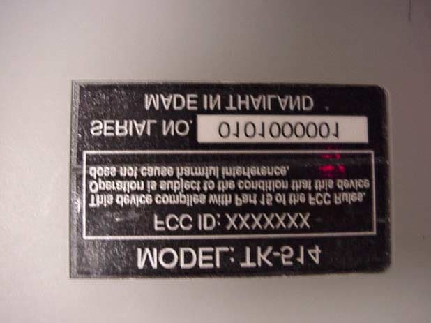
Click to zoom
Application Details
- Equipment Class
- FRB - Part 95 Family Radio Base Transmitter
- Date of Grant
- Jun 13, 2001
- Application Purpose
- Original Equipment
- Date of Application
- Jun 13, 2001
- Equipment Note
- Desktop FRS Base Station
- Frequency Range
- 462.56250000 - 467.71250000
- Company
- Midland Radio Corporation
- Country
- United States
Documents & Files
Document Text
Text extracted from the exhibit documents filed with the FCC. Open a document above to read the original.
Users Manual
360 Herndon Parkway Suite 1400 Herndon, VA 20170 http://www.rheintech.com FCC and Canadian Certification Report Page 24 of 50 2001037 Topaz3, L.L.C. FCC ID: O7KTK514 14 MANUAL Thank you for choosing Maxon! For more information, contact: Maxon America, Inc. Consumer Products Division 10828 NW Air World Drive Kansas City, Missouri 64153 (Within USA) Phone: 1-800-821-7848, Ext. 399 (Outside USA) Phone: 1-816-891-6320, Ext. 399 Fax: 816/891-8815 or explore our website: www.maxonusa.com Printed in Thailand TK514 FRS BASE STATION UHF TWO-WAY RADIO VOX LOW MIC PTT FUNC CALL HIGH PTT POWER CHANNEL VOLUME DOWN MON UP WARRANTY STATEMENT The Consumer Products Division of Maxon America, Inc. (hereinafter referred to as “Maxon”), warrants that is Products and their included accessories will be free from defects in workmanship or materials under normal use for a period of one (1) year from date of purchase by the original end user, provided that buyer has complied with the requirements stated herein. If the Product fails to function under normal use because of manufacturing defect(s) or workmanship during the one (1) year period following the date of purchase, it will be replace or repaired at Maxon’s option at no charge when returned to the place of purchase. The defective unit must be accompanied by proof of the date of purchase in the form of a sales receipt. Maxon’s sole obligation hereunder shall be to repair or replace the product covered in this Warranty. Replacement, at Maxon’s option, may include a similar or higher-featured product. Repair may include the replacement of parts or boards with functionally equivalent reconditioned or new parts or boards. Replace parts, accessories or boards are warranted of the balance of the original time period. All replaced parts, accessories or boards become the property of Maxon America, Inc. Maxon shall have no obligation to make repairs or to cause replacement required which results from normal wear and tear or is necessitated in whole or in part by catastrophe, fault or negligence of the user, improper or unauthorized alterations, repairs the Product, incorrect wiring, use of the product in a manner for which it was not designed, or by causes external to the product. This warranty is void if the serial number is altered, defaced or removed. The purchase shall provide for removal of the defective Product and installation of its replacement. THE EXPRESS WARRANTIES CONTAINED HEREIN ARE IN LIEU OF ALL OTHER WARRANTIES, EITHER EXPRESSED OR IMPLIED OR STATUTORY, INCLUDING, WITHOUT LIMITATION, ANY WARRANTY OF MERCHANTABLILITY OR FITNESS FOR A PARTICULAR PURPOSE. FOR ANY PRODUCT WHICH DOES NOT COMPLY WITH THE WARRANTY SPECIFIED, THE SOLE REMEDY WILL BE REPAIR OR REPLACEMENT. IN NO EVENT WILL MAXON AMERICA, INC. BE LIABLE TO THE BUYER OR ITS CUSTOMERS FOR ANY DAMAGES, INCLUDING ANY SPECIAL,INCIDENTAL, INDIRECT OR CONSEQUENTIAL DANAGES, OR THE LOSS OF PROFIT, REVENUE OR DATA ARISING OUT OF THE USE OF OR THE INABILITY TO USE THE PRODUCT. This warranty is void for sales and deliveries outside of the U.S.A. 20 CONTENTS Important Information............................................... 2 FCC Information...................................................... 3 FCC Warning....................................................... 3 Introduction............................................................ 4 Getting to know Your FRS Base station........................ 5 LCD Display........................................................... 7 Power Source......................................................... 8 Using Your FRS Base station..................................... 9 Turning ON / OFF............................................. 9 Channel Selecting............................................. 9 CTCSS Selecting.............................................. 9 Receiving / Transmitting.................................... 10 Sending Call Tone............................................. 10 Monitor / Backlighting......................................... 11 Power Save Mode............................................. 11 Listening to Weather Channels........................... 11 Weather Alert................................................... 11 Programming Memory Location........................... 12 Memory Channel Recall / Talk............................. 12 Scan Function.................................................. 13 Memory Scan Function...................................... 13 Dual Watch Function.......................................... 14 Talk Confirmation Tone...................................... 14 Tone Setting.................................................... 14 VOX Mode optional.................................................. 15 Application to Baby Monitor............................................... 16 Specifications......................................................... 17 Frequency Table...................................................... 17 Trouble shooting..................................................... 18 Warranty Service Instructions.................................... 19 Warranty Statement................................................... 20 IMPORTANT INFORMATION To get the most out of your TK514 BASE Station, please READ THESE INSTRUCTIONS before attempting to use your new radio. SAVE THSES INSTRUCTIONS –they contain important operation and safety information. YOUR TK514 FRS BASE Station package contains the following: • TK514 FRS BASE Station with Flexible Antenna (Retractable) • AC Adaptor. • User’s Manual 2 WARRANTY SERVICE INSTRUCTIONS 1. Refer to the section titled “Using Your FRS BASE STATION” in this Owner’s Manual for proper operation and adjustments. 2. If the problem cannot be corrected by reference to this Owner’s manual, return the product with proof of purchase (a sales receipt) to the place of purchase, or call Maxon’s Customer Service Department for assistance, toll-free: 1-800-821-7848, Ext. 499. FOR YOUR RECOR…
Text truncated - open the document above for the full version.
Cover Letter(s)
American Telecommunications Certification Body Inc. 6731 Whittier Ave, McLean, VA 22101 April 26, 2001 RE: Topaz FCC ID: 07KTK514 I have the following comments on the above named application: 1.) To begin, no RF exposure information was received. Therefore I am evaluating it as Transmitter Category VIII (a) equipment according to the TCB RF Exposure Procedures document of Nov .15, 2000 and the TCB exclusion list of December 18, 2000 The device should evaluated in accordance with Section VII of the TCB RF Exposure Procedure. This device is considered a mobile radio per Part 2.1091. 2.) Test report cover page claims .4W ERP. Manual claims .5W. Section 6.1.1 in test report claims .363 watts. There must be agreement with all exhibits. Manual and test report have been revised. 3.) Measurement uncertainty of +/- 1.5dB is appropriate for OATS measurements, but too much for radiated power measurements using substitution method. Variances of less than 0.5dB would be more appropriate. Please address. Test report has been revised to account for a +/- 0.5dB measurement uncertainty. Section 6.1.1 4.) TCB Transmitter Exposure Procedures document Section VIII (a) of Nov. 15, 2000 excludes devices above 400mW. Converting your measured ERP to EIRP puts you at almost 600mW. Please address. Section VII of the TCB RF Exposure Procedure is to be used. Please refer to Item 1. The device meets the categorically exclusion limits per Part 2.1091. 5.) FYI: It is preferable for all narrowband emissions using 12.5KHz channel spacing to use a SA span of 50KHz 6.) FYI: Please separate unmodulated from modulated plots. It is difficult to read when both are crammed on one display and printed on a black and white printer. Noted: Please buy a color printer as this will be easier for you to identify color coded data. William H. Graff Examining Engineer President and Director of Engineering mailto:[email protected] The items indicated above must be submitted before processing can continue on the above referenced application. Failure to provide the requested information may result in application termination. Correspondence should be considered part of the permanent submission and may be viewed from the Internet after a Grant of Equipment Authorization is issued. l Page 2 May 17, 2001 Please do not respond to this correspondence using the email reply button. In order for your response to be processed expeditiously, you must submit your documents through the AmericanTCB.com website. Also, please note that partial responses increase processing time and should not be submitted. Any questions about the content of this correspondence should be directed to the sender.
Cover Letter(s)
American Telecommunications Certification Body Inc. 6731 Whittier Ave, McLean, VA 22101 April 26, 2001 RE: Topaz FCC ID: 07KTK514 I have the following comments on the above named application: 1.) To begin, no RF exposure information was received. Therefore I am evaluating it as Transmitter Category VIII (a) equipment according to the TCB RF Exposure Procedures document of Nov .15, 2000 and the TCB exclusion list of December 18, 2000 The device should evaluated in accordance with Section VII of the TCB RF Exposure Procedure. This device is considered a mobile radio per Part 2.1091. 2.) Test report cover page claims .4W ERP. Manual claims .5W. Section 6.1.1 in test report claims .363 watts. There must be agreement with all exhibits. Manual and test report have been revised. 3.) Measurement uncertainty of +/- 1.5dB is appropriate for OATS measurements, but too much for radiated power measurements using substitution method. Variances of less than 0.5dB would be more appropriate. Please address. Test report has been revised to account for a +/- 0.5dB measurement uncertainty. Section 6.1.1 4.) TCB Transmitter Exposure Procedures document Section VIII (a) of Nov. 15, 2000 excludes devices above 400mW. Converting your measured ERP to EIRP puts you at almost 600mW. Please address. Section VII of the TCB RF Exposure Procedure is to be used. Please refer to Item 1. The device meets the categorically exclusion limits per Part 2.1091. 5.) FYI: It is preferable for all narrowband emissions using 12.5KHz channel spacing to use a SA span of 50KHz 6.) FYI: Please separate unmodulated from modulated plots. It is difficult to read when both are crammed on one display and printed on a black and white printer. Noted: Please buy a color printer as this will be easier for you to identify color coded data. William H. Graff Examining Engineer President and Director of Engineering mailto:[email protected] The items indicated above must be submitted before processing can continue on the above referenced application. Failure to provide the requested information may result in application termination. Correspondence should be considered part of the permanent submission and may be viewed from the Internet after a Grant of Equipment Authorization is issued. l Page 2 May 17, 2001 Please do not respond to this correspondence using the email reply button. In order for your response to be processed expeditiously, you must submit your documents through the AmericanTCB.com website. Also, please note that partial responses increase processing time and should not be submitted. Any questions about the content of this correspondence should be directed to the sender.
Cover Letter(s)
American Telecommunications Certification Body Inc. 6731 Whittier Ave, McLean, VA 22101 May 22, 2001 RE: Topax3, LLC FCC ID: 07KTK514 I have the following comments on this application. Since most revolve about the RF Exposure rules, please review the TCB Exposure documents you have on file. 1.) The product description and alignment procedure refer to this as a 0.5W conducted radio. The test report in 2.1 says this is a .5W ERP radio. Cover page and test data for this radio say .4W ERP. Which is correct? Conducted output power is 0.5 Watt. ERP power is 0.360 Watt. 2.) RF exposure info talks about 0.4W conducted into a 2.15dBi antenna for a total EIRP of ~. 66W. Without further guidance from the manual, I must assume worst case for a Category VIII equipment. This would exclude it from TCB approval. Please see revised RF Exposure 3.) FYI: Site photos are not required for licensed services. Noted, thank you. RTL policy is to take site photos for all projects and include them in reports. 4.) The antenna is non-detachable. Therefore, power rating on 731 should be in radiated values. Please see revised 731 form. 5.) Temperature Test: Was a power off condition observed during the 10 degree increment intervals? The unit was in a powered on condition while soaking at each temperature and transmission for each sampling moment. 6.) Frequency variation over temperature and voltage: Correct units should not be in % deviation. Use parts per million instead. Part 95 §95.627 (b) states "Each FRS unit must be maintained within a frequency tolerance of 0.00025%.", thus the units were reported in percentage. William H. Graff Examining Engineer President and Director of Engineering mailto:[email protected] The items indicated above must be submitted before processing can continue on the above referenced application. Failure to provide the requested information may result in application termination. Correspondence should be considered part of the permanent submission and may be viewed from the Internet after a Grant of Equipment Authorization is issued. Please do not respond to this correspondence using the email reply button. In order for your response to be processed expeditiously, you must submit your documents through the AmericanTCB.com website. Also, please note that partial responses increase processing time and should not be submitted. Any questions about the content of this correspondence should be directed to the sender.
Cover Letter(s)
American Telecommunications Certification Body Inc. 6731 Whittier Ave, McLean, VA 22101 May 22, 2001 RE: Topax3, LLC FCC ID: 07KTK514 I have the following comments on this application. Since most revolve about the RF Exposure rules, please review the TCB Exposure documents you have on file. 1.) The product description and alignment procedure refer to this as a 0.5W conducted radio. The test report in 2.1 says this is a .5W ERP radio. Cover page and test data for this radio say .4W ERP. Which is correct? Conducted output power is 0.5 Watt. ERP power is 0.360 Watt. 2.) RF exposure info talks about 0.4W conducted into a 2.15dBi antenna for a total EIRP of ~. 66W. Without further guidance from the manual, I must assume worst case for a Category VIII equipment. This would exclude it from TCB approval. Please see revised RF Exposure 3.) FYI: Site photos are not required for licensed services. Noted, thank you. RTL policy is to take site photos for all projects and include them in reports. 4.) The antenna is non-detachable. Therefore, power rating on 731 should be in radiated values. Please see revised 731 form. 5.) Temperature Test: Was a power off condition observed during the 10 degree increment intervals? The unit was in a powered on condition while soaking at each temperature and transmission for each sampling moment. 6.) Frequency variation over temperature and voltage: Correct units should not be in % deviation. Use parts per million instead. Part 95 §95.627 (b) states "Each FRS unit must be maintained within a frequency tolerance of 0.00025%.", thus the units were reported in percentage. William H. Graff Examining Engineer President and Director of Engineering mailto:[email protected] The items indicated above must be submitted before processing can continue on the above referenced application. Failure to provide the requested information may result in application termination. Correspondence should be considered part of the permanent submission and may be viewed from the Internet after a Grant of Equipment Authorization is issued. Please do not respond to this correspondence using the email reply button. In order for your response to be processed expeditiously, you must submit your documents through the AmericanTCB.com website. Also, please note that partial responses increase processing time and should not be submitted. Any questions about the content of this correspondence should be directed to the sender.
Cover Letter(s)
American Telecommunications Certification Body Inc. 6731 Whittier Ave, McLean, VA 22101 June 5, 2001 RE: Topaz3, LLC FCC ID: 07KTK514 Most of my comments from the May 22 notations on this device were addressed. There is one issue that still needs resolution. 1.) Temperature Test: Please refer to TIA/EIA 603. The Methods of Measurement for Unit Characteristics section is the closest to the intent for the FCC temperature test. Under 2.3.2 Temperature Range you will find 2.3.2.2 Method of Measurement. Pay specific attention to section c), d), e), and f). It is as important to note this in any test report for Licensed transmitters, as it is to note testing in “three orthogonal planes” for Part 15 devices subject to the methodology of ANSI C63.4. Please consider revising your procedures to allow for a power off condition when incrementing in 10 degree increments. We noted your reference to section 2.3.2 of TIA/EIA 603. The test report section “7.1.1 Procedures”, indicates reference to the appropriate standard used. The procedure outlined specifies the following: “The frequency stability was measured within one minute after application of primary power to the transmitter... A ½ an hour period was observed to stabilize the EUT at each measurement step and the frequency stability was measured within one minute after application of primary power to the transmitter. ” Consequently, the power off condition is effective between two temperature increments of 10 degrees. 2.) My final comment from the May 22 letter was mis-spoken. The intent was as a FYI: preferred units should be in ppm. William H. Graff Examining Engineer President and Director of Engineering mailto:[email protected] The items indicated above must be submitted before processing can continue on the above referenced application. Failure to provide the requested information may result in application termination. Correspondence should be considered part of the permanent submission and may be viewed from the Internet after a Grant of Equipment Authorization is issued. Please do not respond to this correspondence using the email reply button. In order for your response to be processed expeditiously, you must submit your documents through the AmericanTCB.com website. Also, please note that partial responses increase processing time and should not be submitted. Any questions about the content of this correspondence should be directed to the sender.
Cover Letter(s)
American Telecommunications Certification Body Inc. 6731 Whittier Ave, McLean, VA 22101 June 5, 2001 RE: Topaz3, LLC FCC ID: 07KTK514 Most of my comments from the May 22 notations on this device were addressed. There is one issue that still needs resolution. 1.) Temperature Test: Please refer to TIA/EIA 603. The Methods of Measurement for Unit Characteristics section is the closest to the intent for the FCC temperature test. Under 2.3.2 Temperature Range you will find 2.3.2.2 Method of Measurement. Pay specific attention to section c), d), e), and f). It is as important to note this in any test report for Licensed transmitters, as it is to note testing in “three orthogonal planes” for Part 15 devices subject to the methodology of ANSI C63.4. Please consider revising your procedures to allow for a power off condition when incrementing in 10 degree increments. We noted your reference to section 2.3.2 of TIA/EIA 603. The test report section “7.1.1 Procedures”, indicates reference to the appropriate standard used. The procedure outlined specifies the following: “The frequency stability was measured within one minute after application of primary power to the transmitter... A ½ an hour period was observed to stabilize the EUT at each measurement step and the frequency stability was measured within one minute after application of primary power to the transmitter. ” Consequently, the power off condition is effective between two temperature increments of 10 degrees. 2.) My final comment from the May 22 letter was mis-spoken. The intent was as a FYI: preferred units should be in ppm. William H. Graff Examining Engineer President and Director of Engineering mailto:[email protected] The items indicated above must be submitted before processing can continue on the above referenced application. Failure to provide the requested information may result in application termination. Correspondence should be considered part of the permanent submission and may be viewed from the Internet after a Grant of Equipment Authorization is issued. Please do not respond to this correspondence using the email reply button. In order for your response to be processed expeditiously, you must submit your documents through the AmericanTCB.com website. Also, please note that partial responses increase processing time and should not be submitted. Any questions about the content of this correspondence should be directed to the sender.
Cover Letter(s)
Engineering and Testing for EMC and Safety Compliance 360 Herndon Parkway, Suite 1400 Herndon, VA 20170 Phone: 703-689-0368; Fax: 703-689-2056; Metro: 703-471-6441 April 4, 2001 Federal Communications Commission 7435 Oakland Mills Road Columbia, MD 21046 To Whom It May Concern: The following information is to be held confidential pursuant of 47 CFR Part 0 §0.457 and Section 552(b)(4) of the Freedom of Information Act, because the information provided contains trade secrets and proprietary. If made public, the information might be used to the disadvantage of the applicant in the market place. • Schematics • Product Description • Block Diagram • Bill of Materials (Parts List) Best Regards, Melissa Fleming. [email protected] Rhein Tech Laboratories, Inc.
Cover Letter(s)
10828 NW Air World Drive, Kansas City, Missouri 64153 January 23, 2001 Federal Communications Commission EQUIPMENT AUTHORIZATION BRANCH 7435 Oakland Mills Road Columbia, MD 21046 RE: Agent Authorization To Whom It May Concern: Maxon Telecom Co., Ltd., 4F Sewon Venture Town Bldg., 705-18 Yeuksam-Dong, Kangnam- Gu, Seoul, Korea hereby authorizes Rhein Tech Laboratories, Inc. (RTL), 360 Herndon Parkway, Suite 1400, Herndon, VA 20170 to act as agent. APPLICANT ANTI-DRUG ABUSE CERTIFICATION: In signing this letter, Applicant certifies that, in the case of an individual applicant, he or she is not subject to a denial of federal benefits, that includes: FCC benefits, pursuant to Section 5301 of the Anti-Drug Abuse Act of 1988, 21 U.S.C. 853(a), or, in the case of a non-individual applicant. No party to the application is subject to a denial of federal benefits, that includes FCC benefits, pursuant to that section. For the definition of a “party” for these purposes, see 47 CFR 1.2002 (b). Sincerely, JongHui Kim OEM Sales Manager
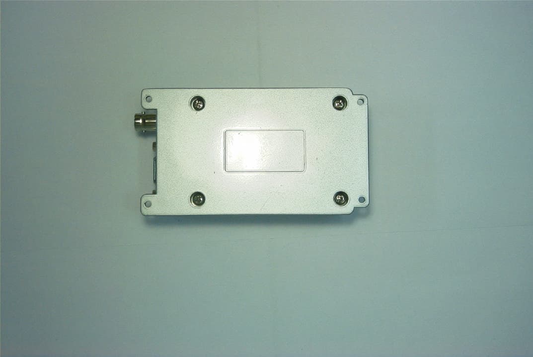
External Photos
360 Herndon Parkway Suite 1400 Herndon, VA 20170 http://www.rheintech.com FCC and Canadian Certification Report Page 35 of 50 2001037 Topaz3, L.L.C. FCC ID: O7KTK514 19 EXTERNAL PHOTOGRAPHS Top 360 Herndon Parkway Suite 1400 Herndon, VA 20170 http://www.rheintech.com FCC and Canadian Certification Report Page 36 of 50 2001037 Topaz3, L.L.C. FCC ID: O7KTK514 Right 360 Herndon Parkway Suite 1400 Herndon, VA 20170 http://www.rheintech.com FCC and Canadian Certification Report Page 37 of 50 2001037 Topaz3, L.L.C. FCC ID: O7KTK514 Front 360 Herndon Parkway Suite 1400 Herndon, VA 20170 http://www.rheintech.com FCC and Canadian Certification Report Page 38 of 50 2001037 Topaz3, L.L.C. FCC ID: O7KTK514 Left 360 Herndon Parkway Suite 1400 Herndon, VA 20170 http://www.rheintech.com FCC and Canadian Certification Report Page 39 of 50 2001037 Topaz3, L.L.C. FCC ID: O7KTK514 Back 360 Herndon Parkway Suite 1400 Herndon, VA 20170 http://www.rheintech.com FCC and Canadian Certification Report Page 40 of 50 2001037 Topaz3, L.L.C. FCC ID: O7KTK514 Bottom 360 Herndon Parkway Suite 1400 Herndon, VA 20170 http://www.rheintech.com FCC and Canadian Certification Report Page 41 of 50 2001037 Topaz3, L.L.C. FCC ID: O7KTK514 Rear Outlets/Antenna Connection 360 Herndon Parkway Suite 1400 Herndon, VA 20170 http://www.rheintech.com FCC and Canadian Certification Report Page 42 of 50 2001037 Topaz3, L.L.C. FCC ID: O7KTK514 Label on bottom
ID Label/Location Info
360 Herndon Parkway Suite 1400 Herndon, VA 20170 http://www.rheintech.com FCC and Canadian Certification Report Page 23 of 50 2001037 Topaz3, L.L.C. FCC ID: O7KTK514 13 LABEL INFORMATION 13.1 WARNING LABEL Dimensions (L): 39.20 mm MAX, 39.1 mm NOMINAL (W): 13.00 mm MAX, 12.9 mm NOMINAL 13.2 FCC ID LABEL Dimensions (L): 39.20 mm MAX, 39.1 mm NOMINAL (W): 16.00 mm MAX, 15.9 mm NOMINAL 13.3 LOCATION OF LABEL ON EUT CAUTION: Device must be restricted to occupational use to satisfy FCC RF exposure compliance. See owner’s manual for specific operating requirements. Topaz3, L.L.C. Serial Number: XXXXXXX FCC ID: O7KTK514 Canada: XXXXX
Internal Photos
360 Herndon Parkway Suite 1400 Herndon, VA 20170 http://www.rheintech.com FCC and Canadian Certification Report Page 43 of 50 2001037 Topaz3, L.L.C. FCC ID: O7KTK514 20 INTERNAL PHOTOGRAPHS 10 and 100 pF caps 360 Herndon Parkway Suite 1400 Herndon, VA 20170 http://www.rheintech.com FCC and Canadian Certification Report Page 44 of 50 2001037 Topaz3, L.L.C. FCC ID: O7KTK514 top of LCD PCB 360 Herndon Parkway Suite 1400 Herndon, VA 20170 http://www.rheintech.com FCC and Canadian Certification Report Page 45 of 50 2001037 Topaz3, L.L.C. FCC ID: O7KTK514 Bottom of LCD PCB 360 Herndon Parkway Suite 1400 Herndon, VA 20170 http://www.rheintech.com FCC and Canadian Certification Report Page 46 of 50 2001037 Topaz3, L.L.C. FCC ID: O7KTK514 LCD PCB in top of case. 360 Herndon Parkway Suite 1400 Herndon, VA 20170 http://www.rheintech.com FCC and Canadian Certification Report Page 47 of 50 2001037 Topaz3, L.L.C. FCC ID: O7KTK514 bottom of main PCB Bottom of PCB with shields removed 360 Herndon Parkway Suite 1400 Herndon, VA 20170 http://www.rheintech.com FCC and Canadian Certification Report Page 48 of 50 2001037 Topaz3, L.L.C. FCC ID: O7KTK514 Inside bottom of case with main PCB 360 Herndon Parkway Suite 1400 Herndon, VA 20170 http://www.rheintech.com FCC and Canadian Certification Report Page 49 of 50 2001037 Topaz3, L.L.C. FCC ID: O7KTK514 top of main PCB in case 360 Herndon Parkway Suite 1400 Herndon, VA 20170 http://www.rheintech.com FCC and Canadian Certification Report Page 50 of 50 2001037 Topaz3, L.L.C. FCC ID: O7KTK514 top PCB with shields removed 360 Herndon Parkway Suite 1400 Herndon, VA 20170 http://www.rheintech.com FCC and Canadian Certification Report Page 51 of 50 2001037 Topaz3, L.L.C. FCC ID: O7KTK514 360 Herndon Parkway Suite 1400 Herndon, VA 20170 http://www.rheintech.com FCC and Canadian Certification Report Page 52 of 50 2001037 Topaz3, L.L.C. FCC ID: O7KTK514 360 Herndon Parkway Suite 1400 Herndon, VA 20170 http://www.rheintech.com FCC and Canadian Certification Report Page 53 of 50 2001037 Topaz3, L.L.C. FCC ID: O7KTK514 360 Herndon Parkway Suite 1400 Herndon, VA 20170 http://www.rheintech.com FCC and Canadian Certification Report Page 54 of 50 2001037 Topaz3, L.L.C. FCC ID: O7KTK514
RF Exposure Info
1 FCC Rules and Regulations Part 1.1307, 1.1310, 2.1091, 2.1093: RF EXPOSURES The manufacturer applies for the General Population/Uncontrolled Exposure Environment. The maximum distance, from the antenna at which MPE is met or exceeded, is calculated from the equation relating field strength E in V/m, transmit power P in Watts, transmit antenna numeric gain G, and separation distance in meters: d GP mVE ×× = 30 )/( Power density: 3770 )/( 2 2 E cmmWP d = The limit for general population/uncontrolled exposure environment applicable to Bystanders (at 462.5625MHz) = f(MHz)/1500 in 2 /cmmW 2 MPE Calculation Antenna: 0 dBd, Vertically polarized Frequency A 462.5625MHz Limit for General Population/Uncontrolled Environment (Bystanders): 0.31 2 /cmmW SEPARATION DISTANCE: A minimum separation distance of 20cm is normally maintained between all users, bystanders and the antenna (including any radiating structure) during normal operation of this device. (dBi) Antenna Gain Power B 2.15 (Watt) (in) (cm) 0.4 5 13 Notes: A = Distances are calculated for the largest (worst-case) separation distance B = Conducted Output Average Power delivered to the antenna CONCLUSION: The device complies with the MPE requirements by providing a safe separation distance between the antenna (including any radiating structure) and any persons.
Test Report
Engineering and Testing for EMC and Safety Compliance 360 Herndon Parkway, Suite 1400 Herndon, VA 20170 Phone: 703-689-0368; Fax: 703-689-2056; Metro: 703-471-6441 APPLICATION FOR CERTIFICATION PART 95(B) FRS Topaz3, LLC 10828 NW Air World Drive Kansas City, MO 64153 MODEL: TK - 514 FCC ID: 07KTK514 April 11, 2001 STANDARDS REFERENCED FOR THIS REPORT PART 2; 1999 FREQUENCY ALLOCATIONS AND RADIO TREATY MATTERS; GENERAL RULES AND REGULATIONS PART 15; 1999 RADIO FREQUENCIES DEVICES PART 95; 1998 PERSONAL RADIO SERVICES ANSI C63.4-1992 STANDARD FORMAT MEASUREMENT/TECHNICAL REPORT PERSONAL COMPUTER AND PERIPHERALS ANSI/TIA/EIA 603-1; 1998 ADDENDUM TO ANSI/TIA/EIA 603-1992 RSS-210; Issue 4; 2000 LOW POWER LICENCE-EXEMPT RADIOCOMMUNICATION DEVICES (ALL FREQUENCY BANDS) RSS-102; Issue 1; 1999 EVALUATION PROCEDURE FOR MOBILE AND PORTABLE RADIO TRANSMITTERS WITH RESPECT TO HEALTH CANADA’S SAFETY CODE 6 FOR EXPOSURE OF HUMANS TO RADIO FREQUENCY FIELDS FREQUENCY RANGE MHZ OUTPUT POWER (W) ERP FREQUENCY TOLERANCE EMISSION DESIGNATOR 462.5625-467.7125 0.3600.00025% 11K0F3E REPORT PREPARED BY: Test Engineer: Daniel Baltzell Administrative/Technical Writer: Melissa Fleming Rhein Tech Laboratories, Inc. Document Number: 2001037 No part of this report may be reproduced without the full written approval of Rhein Tech Laboratories, Inc. 360 Herndon Parkway Suite 1400 Herndon, VA 20170 http://www.rheintech.c…
Text truncated - open the document above for the full version.
Contact Information
Applicant
Jeff Brame(Director of Engineering)
Technical Contact
Rhein Tech laboratories, Inc.Bruno Clavier
[email protected]703 689 0368
360 Herndon Parkway · Herndon, Virginia · United States
Test Firm
Rhein Tech Laboratories, Inc.Rick McMurray
Technical Specifications
| # | Rule Parts | Frequency Range | Power Output | Emission | Tolerance |
|---|---|---|---|---|---|
| 1 | 95B | 462.5625 MHz - 467.7125 MHz | 360.00 mW | 11K0F3E | 2.5000000000 ppm |
Other Applications from Midland Radio Corporation
O7KSD161
Jun 12, 2003VHF Radio Transmitter
Equipment Class
TNB - Licensed Non-Broadcast Station Transmitter
O7KSD164
Jun 02, 2003UHF Data Transceiver - Transmitter
Equipment Class
TNB - Licensed Non-Broadcast Station Transmitter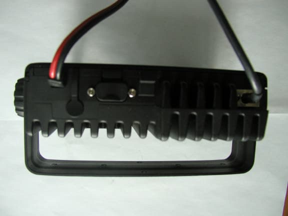
O7KML3245
Jan 27, 2003UHF 32 Channel Mobile Radios
Equipment Class
TNB - Licensed Non-Broadcast Station Transmitter
O7KML3215
Jan 09, 200332 Channel Mobile Radio
Equipment Class
TNB - Licensed Non-Broadcast Station Transmitter
O7KPL5164
May 29, 2002PL5164 Portable Radio
Equipment Class
TNF - Licensed Non-Broadcast Transmitter Held to Face