O7KWX80Weather Alert Radio
Midland Radio Corporation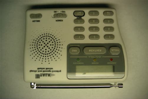
Click to zoom
Application Details
- Equipment Class
- CXX - Communications Rcvr for use w/ licensed Tx and CBs
- Date of Grant
- Apr 26, 2001
- Application Purpose
- Original Equipment
- Date of Application
- Apr 16, 2001
- Equipment Note
- Weather Alert Radio
- Frequency Range
- 162.40000000 - 162.55000000
- Company
- Midland Radio Corporation
- Country
- United States
Documents & Files
Document Text
Text extracted from the exhibit documents filed with the FCC. Open a document above to read the original.
Users Manual
360 Herndon Parkway Suite 1400 Herndon, VA 20170 http://www.rheintech.com FCC Certification Report Page 14 of 25 2001073 / QRTL01-067 Topaz3, L.L.C. FCC ID: O7KWX80 9 MANUAL WX-80 Weather Monitor with SAME User Instruction Manual 2 SPECIFICATIONS Number of Channels ............................................................ 7 Receiver Frequencies (MHz) Channel 1 ...................................................... 162.550 Channel 2 ...................................................... 162.400 Channel 3 ...................................................... 162.475 Channel 4 ...................................................... 162.425 Channel 5 ...................................................... 162.450 Channel 6 ...................................................... 162.500 Channel 7 ...................................................... 162.525 Receiving Sensitivity (at 12 dB SINAD).............................. 0.3uV FIPS Code Sensitivity @ +/- 3KHz Deviation / 90% Success Rate........................... 0.3uV Signal to Noise Ratio...................................................... 40dB Dual Tone Detection Range....................................1.2 to 2.4 KHz Channel Selectivity..........................................+/- 25 KHz, 60dB Power Output (Maximum) .............................................250mW Battery Back-up.............................................One 9-Volt Battery Antenna ............................................. Telescoping Rod Antenna Dimensions(HWD) ................................................ Weight ............................................................... 3 POWERING THE WEATHER RADIO Your Weather radio uses standard 12VDC power for normal operation and one 9V battery (not supplied) for backup power when standard power fails or is temporarily disconnected. For the best performance and longest life, we recommend an alkaline battery. Cautions: l Use only a fresh battery of the required size and recommended type. l Do not use a rechargeable battery in your Weather radio. Notes: l A fresh backup battery will power the Weather radio for up to 1 hour with the weather broadcast turned on or up to 8 hours in alert standby mode. However, we recommend you always connect the Weather radio to AC power for normal use. l If the backup battery becomes weak, your Weather radio might not sound a tone when an emergency or test alert is broadcast. When your radio’s reception periodically, and replace the battery if the tone does net sound. Connecting the Weather radio to AC Power 1. If the Weather radio’s display is on, shift the power switch to the right side until it clicks to turn off the Weather radio. 2. Connect the DC 12V Out of the power ADAPTOR to Weather radio’s DC IN Power 4 Jack. 3. Plug the Weather radio’s DC power ADAPTOR into a standard AC outlet. Installing the Backup Battery 1. If the Weather radio’s display is on, shift power switch to the right side until it clicks to turn off the Weather radio. 2. Press the tab on the battery compartment cover then lift up the cover to remove it. 3. Snap a 9V battery onto the battery terminals inside the compartment, then place the battery inside the compartment. 4. Replace the cover. When REPLACE then BATTERY appears or the Weather radio stops operating when it is unplugged from AC power, replace the battery. Note: REPLACE then BATTERY also appears it no backup battery is installed and the Weather radio is connected to AC power and then turned on. Caution: l Dispose of an old battery promptly and properly. Do not burn or bury it. l Always remove an old or weak battery. Batteries can leak chemicals that can destroy electronic parts. 5 USING THE BUIL-IN ANTENNA The Weather radio’s built-in telescoping antenna lets you receive strong local signals. To use the built-in antenna, lift it up so it is vertical then fully extend it. To improve reception in remote areas, you can connect an external antenna to your Weather radio using an optional adapter cable with a phone plug to the Weather radio’s EXT ANT jack. Your local TOPAZ store sells a wide variety of antennas. To connect an external antenna to the Weather radio, connect one end of the adapter cable to EXT NAT on the back of the Weather radio then connect the other end to the antenna. PROGRAMMING THE WEATHER RADIO The first time you use your Weather radio, it is automatically set to use the NOAA weather broadcast frequency 162.550 MHz (Channel 1) and receive all SAME alert signals broadcast within a 50-mile radius of where you installed it. Your Weather radio is preprogrammed to receive broadcast for the FIPS code stored in first memory location (called single mode), and is preprogrammed with the seven national NOAA broadcast frequencies ( Channels 1-7). Depending on your location, you might need to set it to its multiple mode and select a different channel. Follow these steps to select a different broadcast frequency and set the Weather radio to its single or multiple mode (if necessary), and store or change FIPS codes in the Weather radio’s memory (to narrow the area for which you receive SAME alerts). 1. To turn on the Weather radio, shift the power switch to the left side until it clicks. 2. Push the “Off” key for 2 second to Set MODE to PROFRAM. The Weather radio 6 displays the last selected weather broadcast channel and frequency number. 3. Press WEATHER if necessary to turn on the weather broadcast, then push the VOLUME Up or Down Key so you can hear the broadcast as you make your selection. Note: If you do not press a key for about 45 seconds during Steps 4-8, the Weather radio exits the programming made and saves only those changes stored before the last key press. To continue, start over at Step2. 4. Press a number key (1-7) to listen to the broadcast on that channel. The Weather radio displays the selected channel and its corresponding frequency. Repeat this step until you find the channel broadcasting in your area. Note: If you receive a …
Text truncated - open the document above for the full version.
Cover Letter(s)
Engineering and Testing for EMC and Safety Compliance 360 Herndon Parkway, Suite 1400 Herndon, VA 20170 Phone: 703-689-0368; Fax: 703-689-2056; Metro: 703-471-6441 April 12, 2001 Federal Communications Commission 7435 Oakland Mills Road Columbia, MD 21046 To Whom It May Concern: The following information is to be held confidential pursuant of 47 CFR Part 0 §0.457 and Section 552(b)(4) of the Freedom of Information Act, because the information provided contains trade secrets and proprietary. If made public, the information might be used to the disadvantage of the applicant in the market place. • Schematics • Product Description • Block Diagram (It is rare that the FCC will allow the block diagram to be held confidential.) Best Regards, Melissa Fleming. [email protected] Rhein Tech Laboratories, Inc.
Cover Letter(s)
10828 NW Air World Drive, Kansas City, Missouri 64153 January 23, 2001 Federal Communications Commission EQUIPMENT AUTHORIZATION BRANCH 7435 Oakland Mills Road Columbia, MD 21046 RE: Agent Authorization To Whom It May Concern: Maxon Telecom Co., Ltd., 4F Sewon Venture Town Bldg., 705-18 Yeuksam-Dong, Kangnam- Gu, Seoul, Korea hereby authorizes Rhein Tech Laboratories, Inc. (RTL), 360 Herndon Parkway, Suite 1400, Herndon, VA 20170 to act as agent. APPLICANT ANTI-DRUG ABUSE CERTIFICATION: In signing this letter, Applicant certifies that, in the case of an individual applicant, he or she is not subject to a denial of federal benefits, that includes: FCC benefits, pursuant to Section 5301 of the Anti-Drug Abuse Act of 1988, 21 U.S.C. 853(a), or, in the case of a non-individual applicant. No party to the application is subject to a denial of federal benefits, that includes FCC benefits, pursuant to that section. For the definition of a “party” for these purposes, see 47 CFR 1.2002 (b). Sincerely, JongHui Kim OEM Sales Manager
External Photos
360 Herndon Parkway Suite 1400 Herndon, VA 20170 http://www.rheintech.com FCC Certification Report Page 17 of 25 2001073 / QRTL01-067 Topaz3, L.L.C. FCC ID: O7KWX80 12 EXTERNAL PHOTOGRAPHS Exterior back Exterior front 360 Herndon Parkway Suite 1400 Herndon, VA 20170 http://www.rheintech.com FCC Certification Report Page 18 of 25 2001073 / QRTL01-067 Topaz3, L.L.C. FCC ID: O7KWX80 Exterior bottom Exterior left 360 Herndon Parkway Suite 1400 Herndon, VA 20170 http://www.rheintech.com FCC Certification Report Page 19 of 25 2001073 / QRTL01-067 Topaz3, L.L.C. FCC ID: O7KWX80 Exterior right Exterior top
ID Label/Location Info
360 Herndon Parkway Suite 1400 Herndon, VA 20170 http://www.rheintech.com FCC Certification Report Page 13 of 25 2001073 / QRTL01-067 Topaz3, L.L.C. FCC ID: O7KWX80 8 LABEL INFORMATION LABEL PLACEMENT
Internal Photos
360 Herndon Parkway Suite 1400 Herndon, VA 20170 http://www.rheintech.com FCC Certification Report Page 20 of 25 2001073 / QRTL01-067 Topaz3, L.L.C. FCC ID: O7KWX80 13 INTERNAL PHOTOGRAPHS Interior bottom Interior top 360 Herndon Parkway Suite 1400 Herndon, VA 20170 http://www.rheintech.com FCC Certification Report Page 21 of 25 2001073 / QRTL01-067 Topaz3, L.L.C. FCC ID: O7KWX80 Digital PCB bottom Digital PCB top 360 Herndon Parkway Suite 1400 Herndon, VA 20170 http://www.rheintech.com FCC Certification Report Page 22 of 25 2001073 / QRTL01-067 Topaz3, L.L.C. FCC ID: O7KWX80 RF PCB top RF PCB bottom With Shield 360 Herndon Parkway Suite 1400 Herndon, VA 20170 http://www.rheintech.com FCC Certification Report Page 23 of 25 2001073 / QRTL01-067 Topaz3, L.L.C. FCC ID: O7KWX80 RF PCB bottom with shield removed
Test Report
Engineering and Testing for EMC and Safety Compliance 360 Herndon Parkway, Suite 1400 Herndon, VA 20170 Phone: 703-689-0368; Fax: 703-689-2056; Metro: 703-471-6441 APPLICATION FOR FCC CLASS B CERTIFICATION RECEIVER Topaz3, L.L.C. 10828 NW Air World Drive Kansas City, MO 64153 USA MODEL: WX80 FCC ID: 07KWX80 March 30, 2001 STANDARDS REFERENCED FOR THIS REPORT PART 2; 1999 FREQUENCY ALLOCATIONS AND RADIO TREATY MATTERS; GENERAL RULES AND REGULATIONS PART 15; 1999 RADIO FREQUENCY DEVICES ANSI C63.4-1992 STANDARD FORMAT MEASUREMENT/TECHNICAL REPORT PERSONAL COMPUTER AND PERIPHERALS ANSI/TIA/EIA 603-1; 1998 ADDENDUM TO ANSI/TIA/EIA 603-1992 FREQUENCY RANGE MHZ OUTPUT POWER (W) FREQUENCY TOLERANCE EMISSION DESIGNATOR 162.400-162.550 N/A N/A N/A REPORT PREPARED BY: Test Engineer: Franck Schuppius Rhein Tech Laboratories, Inc. Document Number: 2001073 / QRTL01-067 No part of this report may be reproduced without the full written approval of Rhein Tech Laboratories, Inc. 360 Herndon Parkway Suite 1400 Herndon, VA 20170 http://www.rheintech.com FCC Certification Report Page 2 of 25 2001073 / QRTL01-067 Topaz3, L.L.C. FCC ID: O7KWX80 Table of Contents 1 GENERAL INFORMATION..................................................................................................................................3 1.1 MODIFICATIONS...................................................................................................................................................3 1.2 RELATED SUBMITTAL(S)/GRANT(S)...................................................................................................................3 1.3 TEST METHODOLOGY.........................................................................................................................................3 1.4 TEST FACILITY.....................................................................................................................................................3 2 SYSTEM TEST CONFIGURATION....................................................................................................................4 2.1 JUSTIFICATION.....................................................................................................................................................4 2.2 EXERCISING THE EUT..................................................................................................................................4 2.3 TEST SYSTEM DETAILS.......................................................................................................................................4 2.4 TEST SYSTEM CONFIGURATION PHOTOGRAPH................................................................................................5 3 CONFORMANCE STATEMENT.........................................................................................................................6 4 EMISSIONS EQUIPMENT LIST..........................................................................................................................7 5 CONDUCTED EMISSIONS...................................................................................................................................9 5.1 CONDUCTED EMISSIONS MEASUREMENTS........................................................................................9 5.2 CONDUCTED EMISSIONS DATA (CHANNEL 3 (162.475MHZ)).........................................................................9 6 RADIATED EMISSIONS MEASUREMENTS................................................................................................10 6.1.1 RADIATED EMISSION DATA (channel 3 (162.475Mhz))...............................................................11 6.1.2 Radiated Emissions..................................................................................................................................11 7 PRODUCT DESCRIPTION.................................................................................................................................12 8 LABEL INFORMATION.....................................................................................................................................13 9 MANUAL.................................................................................................................................................................14 10 SCHEMATICS.................................................................................................................................................15 11 BLOCK DIAGRAM........................................................................................................................................16 12 EXTERNAL PHOTOGRAPHS....................................................................................................................17 13 INTERNAL PHOTOGRAPHS.....................................................................................................................20 14 TEST CONFIGURATION PHOTOGRAPHS...........................................................................................24 14.1 CONDUCTED CONFIGURATION PHOTOGRAPHS.............................................................................................24 14.2 RADIATED CONFIGURATION PHOTOGRAPHS................................................................................................25 360 Herndon Parkway Suite 1400 Herndon, VA 20170 http://www.rheintech.com FCC Certification Report Page 3 of 25 2001073 / QRTL01-067 Topaz3, L.L.C. FCC ID: O7KWX80 1 GENERAL INFORMATION The following Application for FCC Type Certification of a Weather Receiver is prepared on behalf of Topaz3, L.L.C. in accordance with Part 2, and Part 15, Subparts A and B of the Federal Communications Commissions rules and regulations. The Equipment Under Test (EUT) was the Model: WX80, FCC ID: 07KWX80. The test results reported in this document relate only to the item that was tested. All measurements contained in this Application were conducted …
Text truncated - open the document above for the full version.
Test Setup Photos
360 Herndon Parkway Suite 1400 Herndon, VA 20170 http://www.rheintech.com FCC Certification Report Page 24 of 25 2001073 / QRTL01-067 Topaz3, L.L.C. FCC ID: O7KWX80 14 TEST CONFIGURATION PHOTOGRAPHS 14.1 CONDUCTED CONFIGURATION PHOTOGRAPHS 360 Herndon Parkway Suite 1400 Herndon, VA 20170 http://www.rheintech.com FCC Certification Report Page 25 of 25 2001073 / QRTL01-067 Topaz3, L.L.C. FCC ID: O7KWX80 14.2 RADIATED CONFIGURATION PHOTOGRAPHS
Contact Information
Applicant
Jeff Brame(Director of Engineering)
Technical Contact
Rhein Tech Laboratories, Ltd.Frank Schupplus
[email protected]703 689 0368
360 Herndon Parkway · Herndon, Virginia · United States
Test Firm
Rhein Tech Laboratories, Inc.Rick McMurray
Technical Specifications
| # | Rule Parts | Frequency Range | Power Output |
|---|---|---|---|
| 1 | 15B | 162.4 MHz - 162.55 MHz | - |
Other Applications from Midland Radio Corporation
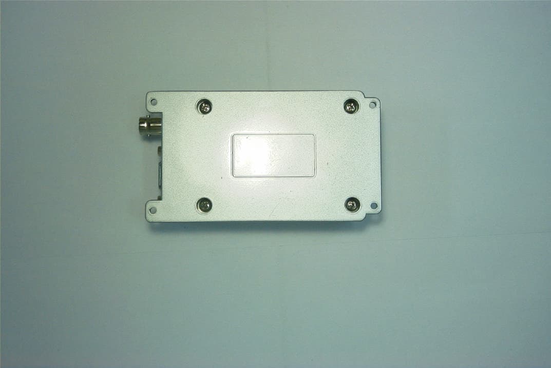
O7KSD161
Jun 12, 2003VHF Radio Transmitter
Equipment Class
TNB - Licensed Non-Broadcast Station Transmitter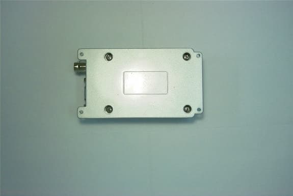
O7KSD164
Jun 02, 2003UHF Data Transceiver - Transmitter
Equipment Class
TNB - Licensed Non-Broadcast Station Transmitter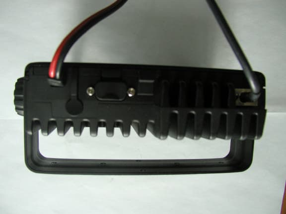
O7KML3245
Jan 27, 2003UHF 32 Channel Mobile Radios
Equipment Class
TNB - Licensed Non-Broadcast Station Transmitter
O7KML3215
Jan 09, 200332 Channel Mobile Radio
Equipment Class
TNB - Licensed Non-Broadcast Station Transmitter
O7KPL5164
May 29, 2002PL5164 Portable Radio
Equipment Class
TNF - Licensed Non-Broadcast Transmitter Held to Face