O8FDKTreo 600 GSM PDA Phone
Palm Inc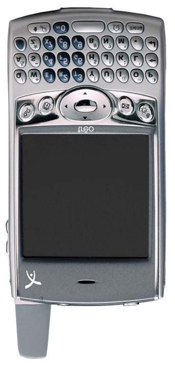
Click to zoom
Application Details
- Equipment Class
- JBP - Part 15 Class B Computing Device Peripheral
- Date of Grant
- Jul 20, 2003
- Application Purpose
- Original Equipment
- Date of Application
- Jul 20, 2003
- Equipment Note
- Treo 600 GSM PDA Phone
- Company
- Palm Inc
- Country
- United States
Documents & Files
Document Text
Text extracted from the exhibit documents filed with the FCC. Open a document above to read the original.
Users Manual
using your Treo Includes setup information and instructions for most tasks Contents 3Contents 5Welcome 6If you read nothing else... 7read this now: getting started 8 What you’ll need 9Treo overview 12Charging the battery 13Inserting the SIM card 14Turning Treo on and off 15Making your first call 17first day: learning the basics 18 Moving around the Treo screen 22Using the keyboard 25Launching applications 27Setting up your computer 30Synchronizing contacts and other personal data 31Battery life 32Where to learn more 33first week: using phone, web, and messaging 34 Phone overview 36Dialing calls 39Receiving calls 40Using voicemail 42Managing active calls 43More ways to manage calls 47Managing contacts 49Defining Favorites buttons 52Using a phone headset 53Browsing the web 60Taking pictures with the camera 64SMS 69MMS 73Sending and receiving messages with Mail 81first two weeks: using organizer features 82 Calendar 87To Do List 90Memo Pad 91CityTime 93Calculator 95Looking up contacts and other information 97Beaming information 99first month: managing applications 100 Installing applications 103Removing applications 104Using Application Info 105Using expansion cards Copyright Copyright © 2003 Handspring, Inc. All rights reserved. Treo and the Treo logo are trademarks of Handspring, Inc., and may be registered in some jurisdictions. Handspring, Blazer and the Handspring logo are trademarks of Handspring, Inc., are registered trademarks in the U.S.A., and may be registered in other jurisdictions. Palm OS and HotSync are registered trademarks, and Palm and the Palm Powered logo are trademarks, of PalmSource, Inc., and are used by Handspring under license. This product contains ACCESS Co., Ltd.’s NetFront 3.0 Internet browser software. © 1996-2003 ACCESS Co., Ltd. and ACCESS Systems America, Inc. NetFront is the trademark or registered trademark of ACCESS Co., Ltd. in Japan and in other countries except the United States of America. NetFront is a registered trademark of NetFront Communications, Inc. in the United States of America and is used under a license. All other trademarks and trade names are the property of their respective owners. Disclaimer and limitation of liability Handspring, Inc. and its suppliers assume no responsibility for any damage or loss resulting from the use of this guide. Handspring, Inc. and its suppliers assume no responsibility for any loss or claims by third parties that may arise through the use of this software. Handspring, Inc. and its suppliers assume no responsibility for any damage or loss caused by deletion of data as a result of malfunction, dead battery, or repairs. Be sure to make backup copies of all important data on other media to protect against data loss. Warranty information In order to obtain warranty service, you must receive warranty service authorization by contacting Handspring within the warranty period and provide dated proof of original purchase. For further information about the warranty service procedure, please visit the Handspring website for your region, or start at www.handspring.com. Software download available Palm™ Desktop software is supplied on a CD-ROM disc. If you do not have access to a CD-ROM drive for your computer, you can download this software from www.handspring.com. 50-1076-00 Welcome:: 5 4 :: Table of Contents Welcome Congratulations on the purchase of your Handspring™ Treo™ phone. You now have •an advanced mobile phone* •a Palm Powered™ organizer with portable expansion capability (SD media) •a digital camera •email* •web browsing* •SMS* •MMS** all in one compact and indispensable device. * Requires service contract with your mobile service provider ** MMS requires MMS services running on GPRS This guide will help you set up your Treo and quickly learn to use it. LOOK HERE: Don’t miss the helpful tips and cross- references given in this column. 109 when you’re ready: customizing your Treo 110 Phone settings 113System Sound settings 114Display and appearance 116Applications Launcher settings 117Button settings 118Date and time settings 120General Preferences 121Locking your phone and data 127 if something happens: help 128 Upgrading from another Palm Powered device 130Trouble installing Palm Desktop? 131Resetting your Treo 133Screen 134Network connection 137Synchronization (HotSync) 140Mail 143Web 144Camera 145Third-party applications 146Errors 147Making room on your Treo 148 glossary 150 FCC 151Index 158Specifications read this now: getting started:: 7 If you read nothing else... This guide is designed to get you using your Treo quickly, starting with just the basics. As you become more comfortable with your Treo and want to learn more, come back and read the other sections. 6:: If you read nothing else... read this now: getting started Read this Now: Getting Started Follow the instructions on pages 7-16 to set up your Treo and make your first call. First Day: Learning the Basics Read through pages 17-32 to learn how to enter text, move around the screen and set up synchronization. First Week: Using Phone, Web and Messaging Learn how to use all the great wireless features of your Treo on pages 33-80, including phone, email, web browsing, and messaging. First Two Weeks: Using Organizer Features Your Treo is not just a phone. It also includes a full-featured Palm Powered organizer that gives you instant access to your Calendar, To Do List, Memo Pad, CityTime, Calculator, and more. See pages 81-98. First Month: Managing Applications Explore pages 99-108 to learn how to add or delete extra applications and use an expansion card with your Treo. When You’re Ready: Customizing your Treo Once you’ve learned the basics, you’ll want to explore additional features on your Treo and customize its settings. See pages 109-126 for information about these features. If Something Happens: Help If something goes wrong or you can’t figure out how to use a Treo feature, we can help. See pages 127-147 for the answers to frequently asked quest…
Text truncated - open the document above for the full version.
Cover Letter(s)
To: Mr. Tim Johnson American Telecommunications Certification Body Inc. 6731 Whittier Ave, McLean, VA 22101 From: David Waitt Sr. Regulatory Engineer, Handspring, Inc July 17, 2003 RE: FCC ID: O8FDK Mr. Johnson, The additional information you requested regarding our recent FCC certification application (FCC ID: O8FBW) is below. I hope this addresses your concerns. If you would like any further information, please do not hesitate to contact me at [email protected] . Your questions are included for your reference below, along with the reply Best Regards David Waitt General ATCB 1) Please provide internal and external photograph exhibits. Handspring) The photos were inadvertently omitted from the initial application. They have now been uploaded to the ATCB site. ATCB 2) Please provide a users manual for this application. Handspring)) The users manual was inadvertently omitted from the initial application. It has now been uploaded to the ATCB site. ATCB 3) Please provide a test configuration photograph exhibit. Handspring) The EMC test setup photos were inadvertently omitted from the initial application. They have now been uploaded to the ATCB site. ATCB 4) Please provide a parts list for this device. If necessary, please update the confidentiality letter. Handspring) A parts list has been uploaded for both the main PC board as well as the GSM RF module. The Confidentiality letter has been revised and uploaded ATCB 5) FYI. Normally the FCC label includes a colon after the term "FCC ID". For future applications it would be best to apply the preferred formatting of "FCC ID:". Handspring) Agreed. The silk screen will be modified. The colon will appear on the device the next time we order plastics for production. Handspring, Inc. 189 Bernardo Ave. Mountain View, CA 94043 ATCB 6) Information in the artwork for the label appears to show the FCC logo. Please explain if this is being utilized on the device and for what approval it pertains. Handspring) This lower left corner of the drawing is simply being used as a “Logo Storage Bin” for various foreign regulatory marks in case future foreign certifications require a regulatory mark. The marks do not appear on the device being certified. The only marks appearing on the device currently being certified are those shown on the back of the unit in the drawing. ATCB 7) Please provide: a) DC voltages/currents applied into the several elements of the final radio frequency amplifying device for normal operation over the power range Handspring) The DC voltage is from the battery and range from 3.6 to 4.2 (depending on the charge of the battery). Current depend on many things like PCL, Display brightness etc. In Peak burst Current drain is ~2A, though over average is more in the 200 - 300 mA range b) Tune up procedure over power range Handspring) A tune up procedure has been uploaded and this document included on the revised confidentiality request letter c) Description of all circuitry and devices provided for determining and stabilizing frequency, for suppression of spurious radiation, for limiting modulation, and for limiting power. Handspring) Frequency is synthesized from a temperature compensated reference oscillator at 13 MHz. Spurious is limited by the use of NZIF (which decrease the amount of spurious). In addition radio is shielded completely. Modulation is generated with I/Q signal's based on lookup table. In addition modulation is checked in manufacturing. Power amplifier have built in power detector and control loop, which keeps power constant over time, temperature and voltage. In addition all radios are individually calibrated EMC Report - 800 MHz GSM ATCB 8) Please correct or add the ERP value for power output to the results in page 7 of 17. Note that the FCC uses ERP for Part 22. Handspring) Power has been included as ERP in the report page 7 of 17. ATCB 9) The low channel block B on page 12 of 31 appears over 700 kHz above the band edge (note the center of the screen is 835.65 MHz and should be 835 MHz). Please confirm if this is the actual lowest channel used in this block. Otherwise please provide a new plot for this bandedge. Handspring) New plot for this request has been re-done. New revised report with data has been uploaded ATCB 10) The 99% occupied bandwidth shows a measurement of 235-237 kHz, yet the 731 form shows 1.3 MHz. Please explain. Note that the FCC typically accepts an emissions designator of 300KGXW for GSM device to Part 24E and 22H. Handspring) The emissions designation entered on the 731 for was an error. The correct emissions designation for this device is 300KGXW ATCB 11) Please explain the rational for selection of measurements during the radiated spurious emissions via the substitution method for channel 191. It does not appear that the highest measurements were selected for test. For instance, it appears that out of the 4 measurements provided for channel 191 that only 1 of these measurements was in the highest 4 emission measured on page 18 of 31. The higher emissions at 2.5, 5.8, 7.5 GHz do not appear to be measured. Handspring) Measurements for 2.5, 5.8, and 7.5 GHz have been included into the substitution table. Report with new data has been uploaded.. ATCB 12) The frequency stability results for temperature look unusually small (page 29 of 31). Please check results to see if they are actually listed properly and the correct units is given in the table (Hz). Handspring) The units of the result should have been MHz. Therefore the drift was actually measured at 887Hz. The EMC report has been corrected ATCB 13) Please explain the derivation of 0.064 ppm on the 731 form as this does not appear to match the test report (0.064 ppm at 836.867 MHz = 54 Hz drift). Handspring) There was an error in the calculation for the 731 form. The correct drift is: 836.867MHz/890Hz = .9403ppm ATCB 14) FYI. As of February 2003, the FCC implemented revisions to Part 22. For future reports, please follow the requirements of these re…
Text truncated - open the document above for the full version.
Cover Letter(s)
To: Mr. Tim Johnson American Telecommunications Certification Body Inc. 6731 Whittier Ave, McLean, VA 22101 From: David Waitt Sr. Regulatory Engineer, Handspring, Inc July 22, 2003 RE: FCC ID: O8FDK Mr. Johnson, The additional information you requested regarding our recent FCC certification application (FCC ID: O8FDK) is below. I hope this addresses your concerns. If you would like any further information, please do not hesitate to contact me at [email protected] . Your questions are included for your reference below, along with the reply Best Regards David Waitt General ATCB 1) Please provide internal photograph of the following: a) Top of the main board with the RF module removed. b) Area underneath the insulation material located on the back of the main board. Handspring ) The requested photos have been uploaded. Note that the metal appearing next to the camera is not a shield enclosing components. It is the back of the shielded SD card enclosure. ATCB 2) It appears that the information regarding the voltage and currents are given for the entire device. Please explain if this information is also valid for the several elements of the final radio frequency amplifying device or if not, please provide this information. Handspring) The information provided is correct for the RF module. Part 15 Class B review ATCB 3) Please provide the test photographs for this testing as part of a separate exhibit. Handspring) Test setup photos have been uploaded as a separate exhibit. ATCB 4) From looking at the operational description, it appears that this device (not including the transceivers) has a 144 MHz clock. According to 15.33(b)(1), this requires digital device emissions testing to be performed up to 2 GHz. It does not appear that this testing was performed. Note that EN55022 does not have this requirement. Handspring) A radiated emissions scan of the device was conducted from 1 to 2 GHz. The highest emissions measured was at 1216.813GHz @ 14.0 dB below the limit. A note indicating this has been added to the revised report. Handspring, Inc. 189 Bernardo Ave. Mountain View, CA 94043 ATCB 5) The conducted emissions appear to be tested to Class B, but page 11 of 14 mentions Class A. Please explain. Handspring) The correct class has been stated in the revised report. The revised report has been uploaded with this reply. ATCB 6) It is not clear the test distance used for Run #2 for Radiated emissions. This appears to be a 3 meter test, but page 4 of 14 mentions 10 meters. Please clarify. Handspring) The distance has been corrected in the revised report. ATCB 7) Please provide the RBW and VBW settings used for the following: a) 30 - 1000 MHz Radiated b) > 1000 MHz Radiated c) 0.15 - 30 MHz Conducted Handspring: a) 30 - 1000 MHz Radiated RBW:120kHz VBW:300kHz b) > 1000 MHz Radiated RBW:1MHz VBW:1MHz c) 0.15 - 30 MHz Conducted RBW: 9kHz VBW:30kHz The notes at the beginning of the report have been edited to include these values. Users Manual ATCB 8) The user manual reports the Head value of SAR for 850 MHz as 1.36 (page 85), however the test report shows 1.49 (SAR report page 6 of 68). Please correct. Handspring: This was an error. The manual will be corrected to reflect the correct SAR value. A revised copy will be uploaded as soon as it is available. ATCB 9) Additionally, from information given in the users manual, the internal module used in the device is designed for operation in both the North American Cellular (850 MHz) and PCS (1900 MHz) bands and also European GSM (900 MHz & 1800 MHz). This application only covers the North American (850 & 1900 MHz) bands. Please provide information that shows that this device is not capable of transmission in the 900 and 1800 MHz bands in the U.S. Additionally, this device will include the following on the grant: "This device contains 900 MHz EGSM and 1800 MHz DCS functions that are not operational in U.S. Territories. This filing is only applicable for the 850 MHz and 1900 MHz GSM operation only. Handspring) An outline of the “network Search” algorithm is outlined below. The Treo 600 GSM will NOT transmit (not even the short access burst) if there's not a bonafide GSM base station in the vicinity. The quad-band radio protocol stack will do the following: 1. Scan in the 1900 /850 band first for a GSM base station signal. 2. If it finds one, it will listen to it for a little while ( < 1 sec) to make sure all the characteristics and system information are properly received. 3. Then it will transmit a short access burst (sort of like a ping) and wait for network to assign it a channel before initiating transmission sequence. 4. If stack does not find any valid GSM signal in the entire band (hundreds of channels), then it will switch over and listen to 900 /1800 band to see if there's anything there. 5. If there's a valid signal with correct broadcast system information, then the stack will attempt access as described above in 2 - 3. 6. If there's nothing there either, then stack will go back to 1900/850 and start the cycle again at 1.
Cover Letter(s)
American Telecommunications Certification Body Inc. 6731 Whittier Ave, McLean, VA 22101 July 15, 2003 RE: Handspring Inc. FCC ID: O8FDK After a review of the submitted information, I have a few comments on the above referenced Application. General 1) Please provide internal and external photograph exhibits. 2) Please provide a users manual for this application. 3) Please provide a test configuration photograph exhibit. 4) Please provide a parts list for this device. If necessary, please update the confidentiality letter. 5) FYI. Normally the FCC label includes a colon after the term "FCC ID". For future applications it would be best to apply the preferred formatting of "FCC ID:". 6) Information in the artwork for the label appears to show the FCC logo. Please explain if this is being utilized on the device and for what approval it pertains. 7) Please provide: a) DC voltages/currents applied into the several elements of the final radio frequency amplifying device for normal operation over the power range b) Tune up procedure over power range c) Description of all circuitry and devices provided for determining and stabilizing frequency, for suppression of spurious radiation, for limiting modulation, and for limiting power. EMC Report - 800 MHz GSM 8) Please correct or add the ERP value for power output to the results in page 7 of 17. Note that the FCC uses ERP for Part 22. 9) The low channel block B on page 12 of 31 appears over 700 kHz above the band edge (note the center of the screen is 835.65 MHz and should be 835 MHz). Please confirm if this is the actual lowest channel used in this block. Otherwise please provide a new plot for this bandedge. 10) The 99% occupied bandwidth shows a measurement of 235-237 kHz, yet the 731 form shows 1.3 MHz. Please explain. Note that the FCC typically accepts an emissions designator of 300KGXW for GSM device to Part 24E and 22H. 11) Please explain the rational for selection of measurements during the radiated spurious emissions via the substitution method for channel 191. It does not appear that the highest measurements were selected for test. For instance, it appears that out of the 4 measurements provided for channel 191 that only 1 of these measurements was in the highest 4 emission measured on page 18 of 31. The higher emissions at 2.5, 5.8, 7.5 GHz do not appear to be measured. 12) The frequency stability results for temperature look unusually small (page 29 of 31). Please check results to see if they are actually listed properly and the correct units is given in the table (Hz). 13) Please explain the derivation of 0.064 ppm on the 731 form as this does not appear to match the test report (0.064 ppm at 836.867 MHz = 54 Hz drift). 14) FYI. As of February 2003, the FCC implemented revisions to Part 22. For future reports, please follow the requirements of these revisions, as it will make reviewing the reports much easier since many section references are different than previously. Attached is a copy of the changes to Part 22. EMC Report - 1900 MHz GSM 15) Please explain the 0.011 ppm listed for 1900 MHz CDMA. It appears from the report this should be 0.669 ppm based on 1240 Hz at 1854 MHz. --- Continued on Next Page --- l Page 2July 17, 2003 SAR Report 16) The FCC asks that we compare the EMC and SAR power measurements for purposes of ensuring the power during SAR was set to maximum. However the EMC reports only listed ERP and EIRP power measurements while the SAR report included conducted measurements. Please explain how a comparison between the 2 can be shown. Timothy R. Johnson Examining Engineer mailto: [email protected] The items indicated above must be submitted before processing can continue on the above referenced application. Failure to provide the requested information may result in application termination. Correspondence should be considered part of the permanent submission and may be viewed from the Internet after a Grant of Equipment Authorization is issued. Please do not respond to this correspondence using the email reply button. In order for your response to be processed expeditiously, you must submit your documents through the AmericanTCB.com website. Also, please note that partial responses increase processing time and should not be submitted. Any questions about the content of this correspondence should be directed to the sender.
Cover Letter(s)
American Telecommunications Certification Body Inc. 6731 Whittier Ave, McLean, VA 22101 July 19, 2003 RE: Handspring Inc. FCC ID: O8FDK After a review of the submitted information, I have a few comments on the above referenced Application. General 1) Please provide internal photograph of the following: a) Top of the main board with the RF module removed. b) Area underneath the insulation material located on the back of the main board. 2) It appears that the information regarding the voltage and currents are given for the entire device. Please explain if this information is also valid for the several elements of the final radio frequency amplifying device or if not, please provide this information. Part 15 Class B review 3) Please provide the test photographs for this testing as part of a separate exhibit. 4) From looking at the operational description, it appears that this device (not including the transceivers) has a 144 MHz clock. According to 15.33(b)(1), this requires digital device emissions testing to be performed up to 2 GHz. It does not appear that this testing was performed. Note that EN55022 does not have this requirement. 5) The conducted emissions appear to be tested to Class B, but page 11 of 14 mentions Class A. Please explain. 6) It is not clear the test distance used for Run #2 for Radiated emissions. This appears to be a 3 meter test, but page 4 of 14 mentions 10 meters. Please clarify. 7) Please provide the RBW and VBW settings used for the following: a) 30 - 1000 MHz Radiated b) > 1000 MHz Radiated c) 0.15 - 30 MHz Conducted Users Manual 8) The user manual reports the Head value of SAR for 850 MHz as 1.36 (page 85), however the test report shows 1.49 (SAR report page 6 of 68). Please correct. 9) Additionally, from information given in the users manual, the internal module used in the device is designed for operation in both the North American Cellular (850 MHz) and PCS (1900 MHz) bands and also European GSM (900 MHz & 1800 MHz). This application only covers the North American (850 & 1900 MHz) bands. Please provide information that shows that this device is not capable of transmission in the 900 and 1800 MHz bands in the U.S. Additionally, this device will include the following on the grant: "This device contains 900 MHz EGSM and 1800 MHz DCS functions that are not operational in U.S. Territories. This filing is only applicable for the 850 MHz and 1900 MHz GSM operation only. Timothy R. Johnson Examining Engineer mailto: [email protected] The items indicated above must be submitted before processing can continue on the above referenced application. Failure to provide the requested information may result in application termination. Correspondence should be considered part of the permanent submission and may be viewed from the Internet after a Grant of Equipment Authorization is issued. l Page 2July 21, 2003 Please do not respond to this correspondence using the email reply button. In order for your response to be processed expeditiously, you must submit your documents through the AmericanTCB.com website. Also, please note that partial responses increase processing time and should not be submitted. Any questions about the content of this correspondence should be directed to the sender.
Cover Letter(s)
July 16, 2003 Federal Communications Commission Office of Engineering and Technology Equipment Authorization Division 7345 Oakland Mills Road Columbia, Maryland 21046 Subject: Confidentiality request for FCC ID: O8FDK To whom it may concern, Handspring requests that the following documents contained in this certification application be withheld from public disclosure. All schematic diagrams (“Treo_600_Schematic_main_PCA.pdf”) (“GSM_RF_Module_schematic.pdf”) All electrical block diagrams (“Treo_600_Block_Diagram.pdf”) All Theory of operations (“Treo_600_Hardware_Spec.pdf”) All Parts Lists (“Parts_list_Treo600_main_PCboard.pdf”) (“Parts_list_Treo600_GSM_module.pdf”) Power Cal / Tune up procedures (“Tune_up_power_cal.pdf”) Handspring also certifies that no party to this application is subject to denial of benefits, including FCC benefits, pursuant to section 5301 of the anti-drug abuse act of 1988, 21 U.S.C 853(a) Sincerely David Waitt Handspring, Inc. 189 Bernardo Ave. Mountain View, CA 94043 Sr. Regulatory Engineer
External Photos
© 2003 Celltech Labs Inc.HANDSPRING INC. FCC ID: O8FDK Treo 600 Dual-Band PCS/Cellular GSM/GPRS Phone EXTERNAL EUT PHOTOGRAPHS © 2003 Celltech Labs Inc.HANDSPRING INC. FCC ID: O8FDK Treo 600 Dual-Band PCS/Cellular GSM/GPRS Phone EXTERNAL EUT PHOTOGRAPHS © 2003 Celltech Labs Inc.HANDSPRING INC. FCC ID: O8FDK Treo 600 Dual-Band PCS/Cellular GSM/GPRS Phone EXTERNAL EUT PHOTOGRAPHS Leather Side Case with Belt-Clip Accessory (P/N: SKU3155WW) © 2003 Celltech Labs Inc.HANDSPRING INC. FCC ID: O8FDK Treo 600 Dual-Band PCS/Cellular GSM/GPRS Phone EXTERNAL EUT PHOTOGRAPHS Fitted Leather Case with Belt-Clip & Ear-Microphone Accessories (P/N:SKU3154WW)
ID Label/Location Info
A B DAT E R ev-01 C V T Artwork, Added F C C a nd C E numbers . 5. 02. 03 R ev-02 C ha nged -00 C olor to N ypro-Da rk G ra y 5. 07. 03 R ev-03 R emoved C row from C olor T a ble 5. 07. 03 Artwork, B ottom H ous ing, P a d P rint, G S M, E urope 51-0652-X X , R ev-03 Ma y 7, 2003 C rea ted by: Da vid H oenig 11.0 25.0 R egula tory a nd P a lm P owered P a d P rinted C olor: S E E C O L O R T AB L E C olor T a ble 51-0652-X X -00 N ypro-Da rk G ra y/P a ntone 8402C P enguin N 217 P a tents P ending O R IG IN A L A R T WO R K C U S 06820682 FCC ID O8FDK Assembled in Mexico
Internal Photos
© 2003 Celltech Labs Inc.HANDSPRING INC. FCC ID: O8FDK Treo 600 Dual-Band PCS/Cellular GSM/GPRS Phone INTERNAL EUT PHOTOGRAPHS © 2003 Celltech Labs Inc.HANDSPRING INC. FCC ID: O8FDK Treo 600 Dual-Band PCS/Cellular GSM/GPRS Phone INTERNAL EUT PHOTOGRAPHS © 2003 Celltech Labs Inc.HANDSPRING INC. FCC ID: O8FDK Treo 600 Dual-Band PCS/Cellular GSM/GPRS Phone INTERNAL EUT PHOTOGRAPHS
Internal Photos
Additional Internal Photographs of the Treo 600 GSM Version Treo 600 Main PCA, RF module removed. Treo 600 Main PCA, Foam removed
Test Report
File: R51751 Page 1 of 13 Electromagnetic Emissions Test Report for Information Technology Equipment Handspring Model: Treo 600 (GSM Version) In Accordance With FCC Part 15, Class B, ICES-003 Class B, VCCI Class B, EN 55022 Class B and AS/NZS 3548 Class B MANUFACTURER: Handspring 189 Bernardo Avenue Mountain View, CA 94043 TEST SITE: Elliott Laboratories, Inc. 684 W. Maude Avenue Sunnyvale, CA 94086 REPORT DATE: July 1, 2003 FINAL TEST DATE: June 27, 2003 AUTHORIZED SIGNATORY: ______________________________ David W. Bare Chief Technical Officer Elliott Laboratories, Inc. is accredited by the A2LA, certificate number 2016-01, to perform the test(s) listed in this report. This report shall not be reproduced, except in its entirety, without the written approval of Elliott Laboratories, Inc. Elliott Laboratories, Inc. -- EMC Department Test Report Report Date: July 1, 2003 File: R51751 Page 2 of 13 pages TABLE OF CONTENTS COVER PAGE .............................................................................................................................................................1 TABLE OF CONTENTS.......................................................................................................................................... 2 SCOPE ....................................................................................................................................................................... 3 OBJECTIVE ............................................................................................................................................................. 3 STATEMENT OF COMPLIANCE ........................................................................................................................ 4 DEVIATIONS FROM THE STANDARDS............................................................................................................ 4 EMISSION TEST RESULTS .................................................................................................................................. 5 CONDUCTED EMISSIONS (MAINS PORT)...................................................................................................... 5 RADIATED EMISSIONS ..................................................................................................................................... 6 MEASUREMENT UNCERTAINTIES ................................................................................................................. 6 EQUIPMENT UNDER TEST (EUT) DETAILS..........................…
Text truncated - open the document above for the full version.
Contact Information
Applicant
Helen Zhao(Sr. Regulatory Compliance Engineer)
Technical Contact
Handspring Inc.David Waitt
[email protected]650 862 3629
189 Bernardo Ave · Mt View, California · United States
Non-Technical Contact
Handspring Inc.David Waitt
[email protected]650 862 3629
Test Firm
Elliott Laboratories LLCDavid Bare
Technical Specifications
| # | Rule Parts | Frequency Range | Power Output |
|---|---|---|---|
| 1 | 15B | - | - |
Other Applications from Palm Inc

O8F-BROY
Feb 21, 2011Phone
Equipment Class
PCE - PCS Licensed Transmitter held to ear
O8F-BROU
Feb 10, 2011Phone
Equipment Class
DXX - Part 15 Low Power Communication Device Transmitter
O8F-ROAE
Oct 18, 2010CDMA/1x EVDO phone with 802.11 b/g and Bluetooth
Equipment Class
DTS - Digital Transmission System
O8F-ROAU
Oct 18, 2010UMTS Phone with 802.11b/g and Bluetooth
Equipment Class
PCE - PCS Licensed Transmitter held to ear
O8F-ROAY
Oct 05, 2010GSM phone with 802.11a/b/g and Bluetooth
Equipment Class
DTS - Digital Transmission System