O9GDVMICTLOW POWER CAR TRANSCEIVER
Trisquare Communications Inc.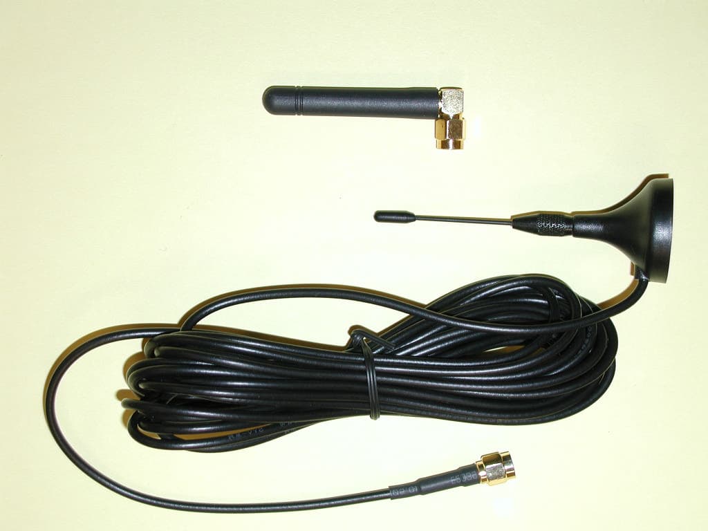
Click to zoom
Application Details
- Equipment Class
- DXX - Part 15 Low Power Communication Device Transmitter
- Date of Grant
- Feb 05, 2006
- Application Purpose
- Original Equipment
- Date of Application
- Feb 05, 2006
- Equipment Note
- LOW POWER CAR TRANSCEIVER
- Frequency Range
- 908.00000000 - 922.00000000
- Country
- United States
Documents & Files
Document Text
Text extracted from the exhibit documents filed with the FCC. Open a document above to read the original.
Users Manual
Operating Instructions Digital Ally DVM-900 Wireless Microphone System Items included in this package with part numbers Description DA Part Number Model Number Remote Transceiver DVM900-RMT DVM-RMT In-Car Transceiver DVM900-ICT DVM-ICT ICT Mount Antenna DVM900-INA DVM-INA Magnetic Roof Mount Antenna DVM900-EXA DVM-EXA In-Car Charger Cradle DVM900-ICC DVM-ICC In-Car Charger Cable DVM900-CCC DVM-CCC Wall-Wart Home Office Charger DVM900-WWC DVM-WWC Belt Clip DVM900-RBC DVM-RBC Lapel Microphone DVM900-ELM DVM-ELM System description: The DVM-900 wireless microphone system operates as part of Digital Ally’s in-car DVR (digital video recorder) system. The DVM-900 wireless microphone system consists of 2 transceivers. The first transceiver, called the In-Car Transceiver (DVM-ICT), is mounted inside the DVM. The second transceiver, called the Remote Transceiver (DVM-RMT), is carried by the patrolman either on his belt or lapel. The Remote Transceiver is a self-contained unit, which includes an internal microphone, external microphone/charge jack, battery charge terminals, internal rechargeable battery, internal antenna, and 2 buttons for Standby/Off and Transmit Record On/Off. The system operates in the 900 MHz ISM (Instrument Scientific Medical) band and is license free. The system range is 1000 feet. The DVM-900 wireless microphone system uses Frequency Hopping Spread Spectrum (FHSS) Narrow Band FM, which provides excellent privacy, security and avoidance of interference. In-Car Transceiver Model Number DVM-ICT Operating Instructions: During setup of the DVR, the operator shall program the In-Car Transceiver. The Remote Transceiver security codes shall also be programmed at DVR setup time by sending the command to SYNC from the DVR to the In-Car Transceiver via the SPI bus. The In-Car Transceiver will then automatically exchange security information with up to two nearby Remote Transceivers that are in ready to SYNC mode. To synchronize the In-Car Transceiver to a new Remote Transceiver, the remote can either be placed in its charging base or the remote can be placed in ready to SYNC mode by turning it on and pressing and holding the REC button for 2 seconds while continuing to hold down the power button. If the Remote is placed in ready to SYNC mode while not in the cradle, the three LEDs shall blink in sequence from red to yellow to green and repeat upon entering programming mode. The command to SYNC must then be sent from the DVR to the ICT. The In-Car Transceiver will first attempt a link confirmation with its one or two previously assigned Remote Transceiver units. When it cannot find any previously assigned Remote Transceivers, it will enter the low power programming mode and attempt to program the new Remote Transceiver. When finished programming, all 3 LEDs shall be ON for 1 second to indicate that programming was effective. A remote that was programmed while not in a charger shall enter Standby mode. To synchronize the In-Car Transceiver with a second Remote Transceiver, remove the first Remote Transceiver from the charging base (if it was programmed in a charging base) and turn it on by pressing and holding the PWR button. Insert the second Remote Transceiver into the charging base or the second remote can be placed in synch mode by turning it on and pressing and holding the REC button for 2 seconds while continuing to hold down the power button. The command to SYNC the second remote must then be sent from the DVR to the ICT. The In-Car Transceiver will confirm the first Remote Transceiver and then proceed to program the second Remote Transceiver. If the second Remote Transceiver unit is confirmed, the process is completed and the In- Car Transceiver shall update the STATUS Register to indicate the number of remotes it has found. Only two Remote Transceivers can be synchronized to an In-Car Transceiver at any point in time. The In-Car Transceiver will add together the audio from the two Remote Transceivers synced to it into a single audio path to be sent to the DVR. If one unit is out of range or is not transmitting, that audio path will be muted. General Specifications: Operating Frequency Range 902 – 928 MHz Operating Voltage 5 VDC Frequency Hopping Sequences 32,768 Frequencies per Sequence 16 Audio Output 250 mV RMS Range 1000 ft FCC Information: This device complies with part 15 of the FCC Rules. Operation is subject to the following two conditions: (1) This device may not cause harmful interference, and (2) this device must accept any interference received, including interference that may cause undesired operation. An FCC license is not required for operation of this device. Important: Use only the supplied antenna. Unauthorized antennas, modifications, or attachments could damage the transmitter and may violate FCC regulations. Remote Transceiver Model Number DVM-RMT Operating instructions: The Remote Transceiver has an internal 550 mA hour rechargeable battery pack. Prior to the first use the battery should be charged for 12 to 15 hours. The Remote Transceiver can be charged through its charge terminals located on the bottom of the unit while placed in the In-Car Charger (DVM-ICC) or through the external mic/charge jack with the Wall Wart Charger (DVM-WWC). After the battery is charged, the Remote Transceiver must be synchronized to the In-Car Transceiver. To synchronize or resynchronize the In-Car Transceiver to one or two Remote Transceivers, place the Remote Transceiver unit(s) into the In-Car Chargers and issue the sync command from the DVM. The In-Car Transceiver will first attempt a link confirmation with assigned Remote Transceiver units in or out of their charging bases. Assigned Remote Transceivers that are not in use should be turned off or placed out of range of the In-Car Transceiver to avoid unintentional resynchronization with units not in use. Power Button External Mic Jack Red LED Yellow LED Green LED Record Button Microphone The In-Car Transceiver will confirm …
Text truncated - open the document above for the full version.
Cover Letter(s)
TriSquare Communications 1420 NW Vivion Rd., Suite 113, Kansas City, Missouri 64118 January 11, 2006 Timco Engineering, Inc. 849 NW State Road 45 P.O. Box 370, Newberry, FL 32669 Ref: FCC ID: O9GDVMICT Request for Confidentiality Dear Sirs: With regard to the referenced application, TriSquare Communications, Inc. is requesting confidentiality of certain sections of the accompanying documents. The documents for which TriSquare Communications, Inc. is requesting confidentiality are: Schematic Diagram Block Diagram Operational Descriptions This request is made under the provisions of Section 0.457(d) of the Commission’s Rules, and Section 552(b)(4) of the Freedom of Information Act. The material for which confidentiality is requested falls within the scope of Section 552(b)(4) as trade secrets and includes material covered by Section 0.459 of the Commission’s Rules. Sincerely, W. Gary Staley President
ID Label/Location Info
SERIAL NO: MODEL NO: DVM-ICT FCC ID: O9GDVMICT MADE IN CHINA SERIAL NO: MODEL NO: DVM-ICT FCC ID: O9GDVMICT MADE IN CHINA DVM-ICT Label Placement
Parts List/Tune Up Info
SEMICONDUCTOR DESIGNATIONS AND FUNCTIONS Model DVM-ICT FCC ID: O9GDVMICT Page 1 Designator Description Function D50 Varactor Diode VCO tuning D51 PIN Diode Transmit offset switch D80 Varactor Diode VCO tuning D100 PIN Diode Transmit/Receive antenna switch D130 GP Diode Dual Pack RX B Squelch temperature compensation D230 GP Diode Dual Pack RX A Squelch temperature compensation D300 Varactor Diode Reference oscillator tuning D400 PIN Diode TX audio limiting D401 PIN Diode TX audio limiting D500 PIN Diode TX/RX band switch Q50 RF Transistors NPN VCO – fundamental transmit and LO Q51 RF Transistors NPN VCO – fundamental transmit and LO Q60 Bias Transistors NPN VCO TX/RX band switch Q80 RF Transistors NPN VCO fundamental transmit and LO Q81 RF Transistors NPN VCO fundamental transmit and LO Q100 RF Transistors NPN 1 st RX LNA Q101 RF Transistors NPN 2nd RX LNA Q110 RF Transistors NPN RX B mixer Q111 RF Transistors NPN RX B IF amp Q130 RF Transistors NPN RX B Squelch noise rectifier Q131 Bias Transistors NPN RX B Squelch disable Q150 Bias Transistors NPN RX B audio mute Q210 RF Transistors NPN RX A mixer Q211 RF Transistors NPN RX A IF amp Q230 RF Transistors NPN RX A Squelch noise rectifier Q231 Bias Transistors NPN RX A Squelch disable Q250 Bias Transistors NPN RX A audio mute Q300 Bias Transistors PNP Transmitter power control Q301 Bias Transistors PNP Receiver power control Q500 RF Transistors NPN Transmitter amp Q801 Bias Transistors NPN Open collector digital output Q802 Bias Transistors NPN Open collector digital output Q805 Bias Transistors NPN CPU reset control U30 Voltage Regulator 3.0V Regulator Circuit U130 Narrowband FM IF RX B IF amplification and mixing, audio amplification and filtering U150 Rail-to-rail Quad Op Amp RX B audio filtering, data filtering U200 Rail-to-rail Quad Op Amp Data squaring circuit U230 Narrowband FM IF RX A IF amplification and mixing, audio amplification and filtering U250 Rail-to-rail Quad Op Amp RX A audio filtering, data filtering U300 Dual PLL Frequency synthesizing U400 Rail-to-rail Quad Op Amp RX audio filtering SEMICONDUCTOR DESIGNATIONS AND FUNCTIONS Model DVM-ICT FCC ID: O9GDVMICT Page 2 U410 Compander Audio expansion U500 Rail-to-rail Quad Op Amp RX and TX audio filtering U800 CPU Transmit/Receive control, data decode, power control U801 Voltage Regulator 5V 5V Regulator Circuit U802 EEPROM Data storage when power is off
Test Report
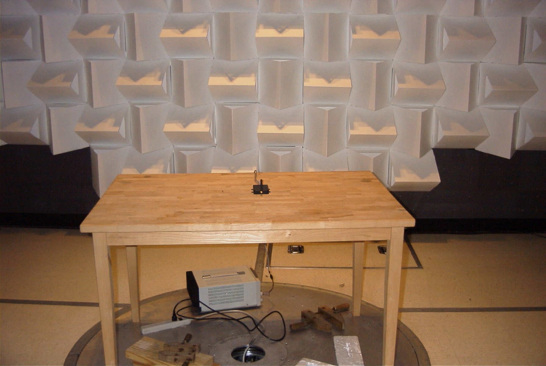
TIMCO ENGINEERING INC. 849 NW State Road 45 Newberry, Florida 32669 http://www.timcoengr.com 888.472.2424 F 352.472.2030 email: [email protected] APPLICANT: TRISQUARE COMMUNICATIONS INC. FCC ID: O9GDVMICT Test Report Product Name: LOW POWER CAR TRANSCEIVER FCC ID: O9GDVMICT Applicant: TRISQUARE COMMUNICATIONS INC. 1420 N.W. VIVION ROAD SUITE 113 KANSAS CITY MO. 64118-4555 USA Date Receipt: 1/23/2006 Date Tested: 1/27/2006 REPORT #: T\Trisquare_O9G\142AUT6\142AUT6TestReport.doc COVER SHEET TIMCO ENGINEERING INC. 849 NW State Road 45 Newberry, Florida 32669 http://www.timcoengr.com 8.472.2424 F 352.472.2030 email: [email protected] 88 APPLICANT: TRISQUARE COMMUNICATIONS INC. FCC ID: O9GDVMICT REPORT #: T\Trisquare_O9G\142AUT6\142AUT6TestReport.doc TABLE OF CONTENTS APPLICANT: TRISQUARE COMMUNICATIONS INC. FCC ID: O9GDVMICT TABLE OF CONTENTS TEST REPORT CONTAINING: PAGE 1...........TEST EQUIPMENT LIST PAGE 2...........TEST PROCEDURE PAGE 3-4.........RADIATION INTERFERENCE TEST DATA PAGE 5-6.........OCCUPIED BANDWIDTH EXHIBIT INCLUDED: REQUEST FOR CONFIDENTIALITY LETTER BLOCK DIAGRAM SCHEMATIC USERS MANUAL LABEL SAMPLE LABEL LOCATION EXTERNAL PHOTOGRAPHS INTERNAL PHOTOGRAPHS OPERATIONAL DESCRIPTION TEST SET UP PHOTOGRPAHS TIMCO ENGINEERING INC. 849 NW State Road 45 Newberry, Florida 32669 http://www.timcoengr.com 888.472.2424 F 352.472.2030 email: [email protected] APPLICANT: TRISQUARE COMMUNICATIONS INC. FCC ID: O9GDVMICT EMC Equipment List Device Manufacturer Model Serial Number Cal/Char Date Due Date 3/10-Meter OATS TEI N/A N/A Listed 3/27/04 3/26/07 3-Meter OATS TEI N/A N/A Listed 1/13/03 1/12/06 Biconnical Antenna Eaton 94455-1 1057 CAL 12/12/05 12/12/07 Biconnical Antenna Eaton 94455-1 1096 CAL 8/17/04 8/17/06 Biconnical Antenna Electro-Metrics BIA-25 1171 CAL 4/29/05 4/29/07 Blue Tower Quasi-Peak Adapter HP 85650A 2811A01279 CAL 4/13/05 4/13/07 Blue Tower RF Preselector HP 85685A 2926A00983 CAL 9/5/05 9/5/07 Blue Tower Spectrum Analyzer HP 8568B 2928A04729 2848A18049 CAL 4/13/05 4/13/07 LISN Electro-Metrics ANS-25/2 2604 CAL 8/27/04 8/27/06 LISN Electro-Metrics EM-7820 2682 CAL 4/28/05 4/28/07 Log-Periodic Antenna Eaton 96005 1243 CAL 12/14/05 12/14/07 REPORT #: T\Trisquare_O9G\142AUT6\142AUT6TestReport.doc Page 1 of 6 TIMCO ENGINEERING INC. 849 NW State Road 45 Newberry, Florida 32669 http://www.timcoengr.com 888.472.2424 F 352.472.2030 email: [email protected] APPLICANT: TRISQUARE COMMUNICATIONS INC. FCC ID: O9GDVMICT TEST PROCEDURE GENERAL: This report shall NOT be reproduced except in full without the written approval of TIMCO ENGINEERING, INC. The UUT was transmitting a test signal during the testing. RADIATION INTERFERENCE: The test procedure used was ANSI STANDARD C63.4-2003 using a HEWLETT PACKARD spectrum analyzer with a pre-selector. The analyzer was calibrated in dB above a microvolt at the output of the antenna. The resolution bandwidth was 100KHz and the video bandwidth was 300KHz up to 1.0GHz and 1.0MHz with a video BW of 3.0MHz above 1.0GHz. The ambient temperature of the UUT was 74.3oF with a humidity of 69%. FORMULA OF CONVERSION FACTORS: The Field Strength at 3m was established by adding the meter reading of the spectrum analyzer (which is set to read in units of dBuV) to the antenna correction factor supplied by the antenna manufacturer. The antenna correction factors are stated in terms of dB. The gain of the Preselector was accounted for in the Spectrum Analyzer Meter Reading. Example: Freq (MHz) METER READING + ACF = FS 33 20 dBuV + 10.36 dB = 30.36 dBuV/m @ 3m POWER LINE CONDUCTED INTERFERENCE: The procedure used was ANSI STANDARD C63.4- 2003 using a 50uH LISN. Both lines were observed. The bandwidth of the spectrum analyzer was 10kHz with an appropriate sweep speed. The ambient temperature of the UUT was 74.3oF with a humidity of 69%. ANSI STANDARD C63.4-2003 10.1.7 MEASUREMENT PROCEDURES: The UUT was placed on a table 80 cm high and with dimensions of 1m by 1.5m. The UUT was placed in the center of the table (1.5m side). The table used for radiated measurements is capable of continuous rotation. When an emission was found, the table was rotated to produce the maximum signal strength. At this point, the antenna was raised and lowered from 1m to 4m. The antenna was placed in both the horizontal and vertical planes. REPORT #: T\Trisquare_O9G\142AUT6\142AUT6TestReport.doc Page 2 of 6 TIMCO ENGINEERING INC. 849 NW State Road 45 Newberry, Florida 32669 http://www.timcoengr.com 888.472.2424 F 352.472.2030 email: [email protected] APPLICANT: TRISQUARE COMMUNICATIONS INC. FCC ID: O9GDVMICT APPLICANT: TRISQUARE COMMUNICATIONS INC. FCC ID: O9GDVMICT NAME OF TEST: RADIATION INTERFERENCE RULES PART NUMBER: 15.249, 15.209 REQUIREMENTS: FIELD STRENGTH FIELD STRENGTH S15.209 of Fundamental: of Harmonics 30 - 88 MHz 40 dBuV/m @3M 902-928 MHZ 88 - 216 MHz 43.5 2.4-2.4835 GHz 216 - 960 MHz 46 94 dBuV/m @3m 54 dBuV/m @3m ABOVE 960 MHz 54dBuV/m EMISSIONS RADIATED OUTSIDE OF THE SPECIFIED FREQUENCY BANDS, EXCEPT FOR HARMONICS, SHALL BE ATTENUATED BY AT LEAST 50 dB BELOW THE LEVEL OF THE FUNDAMENTAL OR TO THE GENERAL RADIATED EMISSION LIMITS IN 15.209, WHICHEVER IS THE LESSER ATTENUATION. THIS DEVICE WILL BE SOLD WITH TWO ANTENNAS – THE FIRST OPTION IS AN ANTENNA MOUNTED DIRECTLY ON THE ICT (DA P/NO. DVM900-INA – MODEL # DVM-INA) AND THE SECOND OPTION IS A MAGNETIC ROOF MOUNT ANTENNA (DA P/NO. DVM900-EXA – MODEL # DVM-EXA). THE DEVICE WAS TESTED WITH BOTH ANTENNAS AND THE ANTENNA WITH THE HIGHEST EMISSIONS IS BEING REPORTED. (THE ANTENNA MOUNTED DIRECTLY ON THE ICT). TEST DATA: Tuned Frequency MHz Emission Frequency MHz Meter Reading dBuV Ant. Polarity Coax Loss dB Correction Factor dB Field Strength dBuV/m Margin dB 908.0 886.27 18.5 H 1.94 23.30 43.74 2.26 908.0 886.56 16.6 V 1.94 22.53 41.07 4.93 908.0 908.00 64.5 V 1.96 22.62 89.08 4.92 908.0 908.00 65.0 H 1.96 23.38 90.34 3.66 908.0 1,772.56 21.4 H 2.72 29.84 53.96 0.04 908.0 1,772.68 21.3 V 2.72 29.84 53.86 0.14 908.0 1,816.00…
Text truncated - open the document above for the full version.
Contact Information
Applicant
Philip Staley(Product Development Manager)
Test Firm
Timco Engineering, Inc.Sid Sanders
Technical Specifications
| # | Rule Parts | Frequency Range | Power Output |
|---|---|---|---|
| 1 | 15C | 908 MHz - 922 MHz | - |
Other Applications from Trisquare Communications Inc.
O9GWBASE
Oct 28, 2007WIRELESS MICROPHONE SYSTEM-BASE
Equipment Class
DXX - Part 15 Low Power Communication Device Transmitter
O9GWMIC
Oct 28, 2007MIC TRANSCEIVER
Equipment Class
DXX - Part 15 Low Power Communication Device Transmitter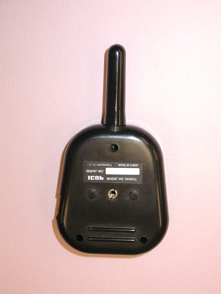
O9G2020ICT
May 02, 2005In Car Transceiver
Equipment Class
DXX - Part 15 Low Power Communication Device Transmitter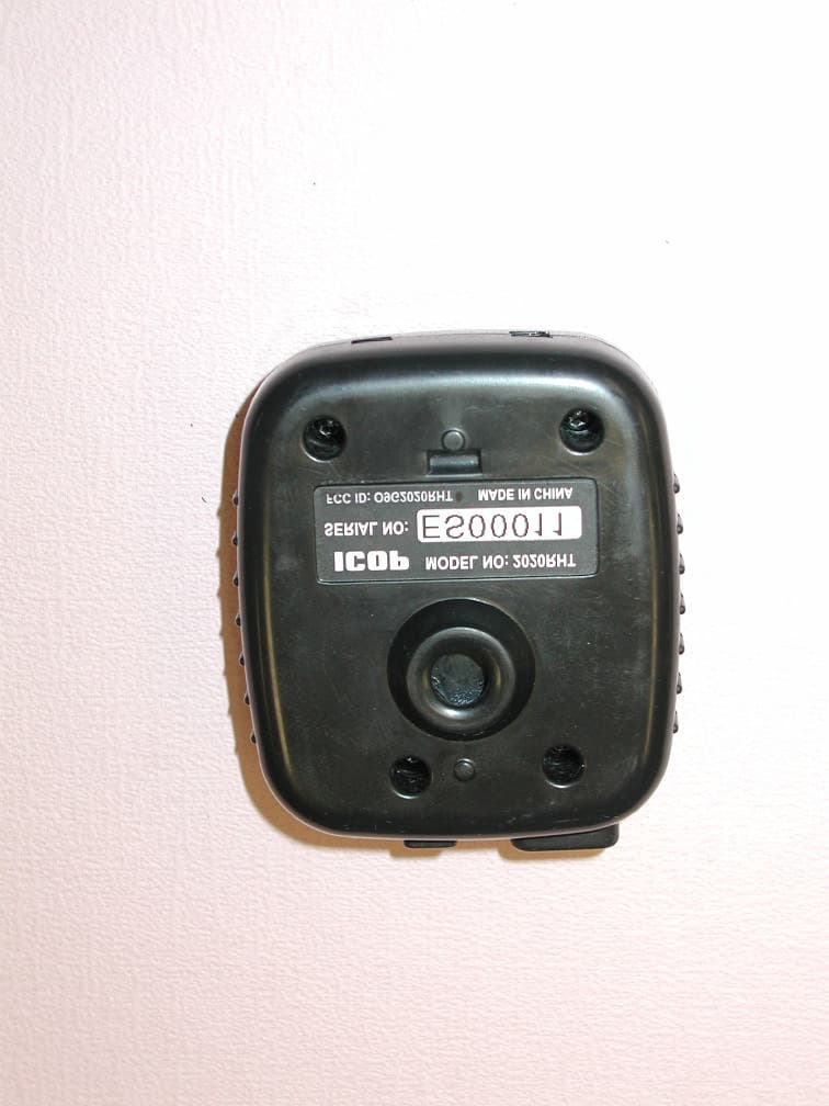
O9G2020RHT
May 01, 2005Remote Transceiver
Equipment Class
DXX - Part 15 Low Power Communication Device Transmitter
O9GGMRS520
May 14, 2002FRS/GMRS Transceiver
Equipment Class
FRF - Part 95 Family Radio Face Held Transmitter