OA3MRF89XAM9A915MHz Ultra Low-Power Communications Device Transmitter
Microchip Technology Inc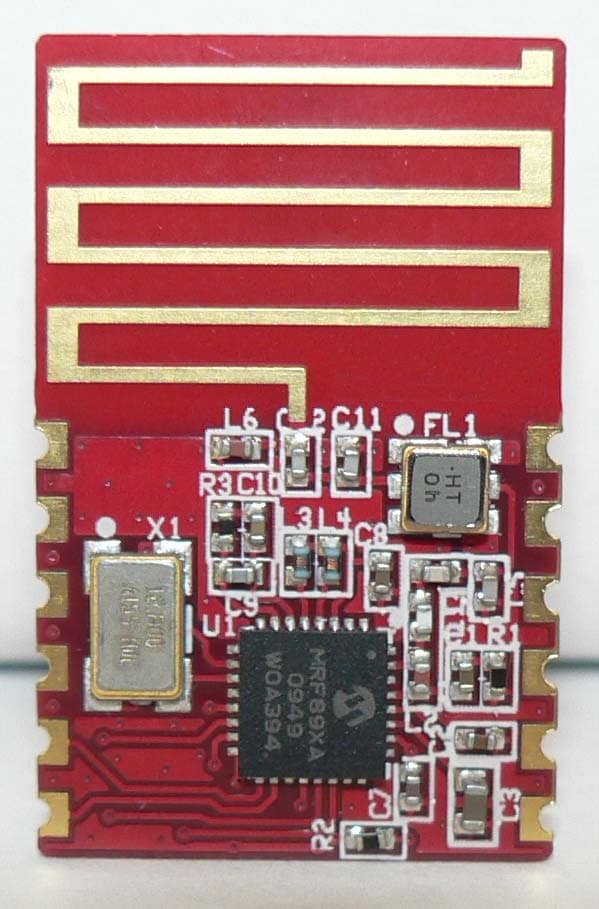
Click to zoom
Application Details
- Equipment Class
- DTS - Digital Transmission System
- Date of Grant
- Jun 05, 2011
- Application Purpose
- Original Equipment
- Date of Application
- Jun 02, 2011
- Equipment Note
- 915MHz Ultra Low-Power Communications Device Transmitter
- Frequency Range
- 903.20000000 - 926.80000000
- Company
- Microchip Technology Inc
- Country
- United States
Documents & Files
Document Text
Text extracted from the exhibit documents filed with the FCC. Open a document above to read the original.
Users Manual
© 2011 Microchip Technology Inc.PreliminaryDS00000A MRF89XAM9A Data Sheet 915 MHz Ultra Low-Power Sub-GHz Transceiver Module DS00000A-page iiPreliminary© 2011 Microchip Technology Inc. Information contained in this publication regarding device applications and the like is provided only for your convenience and may be superseded by updates. It is your responsibility to ensure that your application meets with your specifications. MICROCHIP MAKES NO REPRESENTATIONS OR WARRANTIES OF ANY KIND WHETHER EXPRESS OR IMPLIED, WRITTEN OR ORAL, STATUTORY OR OTHERWISE, RELATED TO THE INFORMATION, INCLUDING BUT NOT LIMITED TO ITS CONDITION, QUALITY, PERFORMANCE, MERCHANTABILITY OR FITNESS FOR PURPOSE. Microchip disclaims all liability arising from this information and its use. Use of Microchip devices in life support and/or safety applications is entirely at the buyer’s risk, and the buyer agrees to defend, indemnify and hold harmless Microchip from any and all damages, claims, suits, or expenses resulting from such use. No licenses are conveyed, implicitly or otherwise, under any Microchip intellectual property rights. Trademarks The Microchip name and logo, the Microchip logo, dsPIC, K EELOQ, KEELOQ logo, MPLAB, PIC, PICmicro, PICSTART, PIC 32 logo, rfPIC and UNI/O are registered trademarks of Microchip Technology Incorporated in the U.S.A. and other countries. FilterLab, Hampshire, HI-TECH C, Linear Active Thermistor, MXDEV, MXLAB, SEEVAL and The Embedded Control Solutions Company are registered trademarks of Microchip Technology Incorporated in the U.S.A. Analog-for-the-Digital Age, Application Maestro, CodeGuard, dsPICDEM, dsPICDEM.net, dsPICworks, dsSPEAK, ECAN, ECONOMONITOR, FanSense, HI-TIDE, In-Circuit Serial Programming, ICSP, Mindi, MiWi, MPASM, MPLAB Certified logo, MPLIB, MPLINK, mTouch, Omniscient Code Generation, PICC, PICC-18, PICDEM, PICDEM.net, PICkit, PICtail, REAL ICE, rfLAB, Select Mode, Total Endurance, TSHARC, UniWinDriver, WiperLock and ZENA are trademarks of Microchip Technology Incorporated in the U.S.A. and other countries. SQTP is a service mark of Microchip Technology Incorporated in the U.S.A. All other trademarks mentioned herein are property of their respective companies. © 2011, Microchip Technology Incorporated, Printed in the U.S.A., All Rights Reserved. Printed on recycled paper. ISBN: Note the following details of the code protection feature on Microchip devices: •Microchip products meet the specification contained in their particular Microchip Data Sheet. •Microchip believes that its family of products is one of the most secure families of its kind on the market today, when used in the intended manner and under normal conditions. •There are dishonest and possibly illegal methods used to breach the code protection feature. All of these methods, to our knowledge, require using the Microchip products in a manner outside the operating specifications contained in Microchip’s Data Sheets. Most likely, the person doing so is engaged in theft of intellectual property. •Microchip is willing to work with the customer who is concerned about the integrity of their code. •Neither Microchip nor any other semiconductor manufacturer can guarantee the security of their code. Code protection does not mean that we are guaranteeing the product as “unbreakable.” Code protection is constantly evolving. We at Microchip are committed to continuously improving the code protection features of our products. Attempts to break Microchip’s code protection feature may be a violation of the Digital Millennium Copyright Act. If such acts allow unauthorized access to your software or other copyrighted work, you may have a right to sue for relief under that Act. Microchip received ISO/TS-16949:2002 certification for its worldwide headquarters, design and wafer fabrication facilities in Chandler and Tempe, Arizona; Gresham, Oregon and design centers in California and India. The Company’s quality system processes and procedures are for its PIC ® MCUs and dsPIC ® DSCs, KEELOQ ® code hopping devices, Serial EEPROMs, microperipherals, nonvolatile memory and analog products. In addition, Microchip’s quality system for the design and manufacture of development systems is ISO 9001:2000 certified. © 2011 Microchip Technology Inc.PreliminaryDS00000A-page 1 MRF89XAM9A Features • Module designed from the MRF89XA Integrated Ultra Low-Power, Sub-GHz Transceiver IC. • Supports MiWi™ Development Environment Proprietary Wireless Networking Protocols • 4-Wire Serial Peripheral Interface (SPI) with Interrupts • Small Size: 0.7" x 1.1" (17.8 mm x 27.9 mm), Surface Mountable — Pin compatible with MRF89XAM9A • Integrated Crystal, Internal Voltage Regulator, Matching Circuitry and Printed Circuit Board (PCB) Antenna • Easy Integration into Final Product — Minimize Product Development, Quicker Time to Market • Compatible with Microchip’s Microcontroller Families (PIC16, PIC18, PIC24, dsPIC33 and PIC32) • Radio Regulation Certified for United States (FCC), Canada (IC) and Australia/New Zealand (C-TICK) Operational • Operating Voltage: 2.1–3.6V (3.3V typical) • Temperature Range: -40°C to +85°C Industrial • Low-Current Consumption: - Rx mode: 3 mA (typical) - Tx mode: 25 mA at +10 dBm (typical) - Sleep: 0.1 μA (typical) RF/Analog Features • ISM Band 902–928 MHz Operation • Modulation: FSK and OOK • Data Rate (to conform to FCC and IC regulations): - FSK: 50–200 kbps - OOK: 16 kbps • Reception sensitivity - FSK: -107 dBm (typical) at 50 kbps - OOK: -113 dBm (typical) at 2 kbps • +10 dBm Typical Output Power with 21 dB Tx Power Control Range Media Access Controller (MAC)/ Baseband Features • Packet handling feature with data whitening and automatic CRC generation • Incoming sync word (pattern) recognition • Built-in bit synchronizer for incoming data, and clock synchronization and recovery • 64-byte transmit/receive FIFO with preload in Stand-by mode • Supports Manchester encoding/decoding techniques Pin diagram 2 3 4 5 6 1 7 …
Text truncated - open the document above for the full version.
Block Diagram
MRF89XAM9A Transceiver Module – Block Diagram MRF89XA transceiver IC SPI Interface RF generation and reception Baseband packet processing Voltage regulator SAW Filter 12.8 MHZ crystal External data source External Power source PCB Antenna
External Photos
MRF89XAM9A Module External Photos Page 1 of 2 Top View MRF89XAM9A Module External Photos Page 2 of 2 Bottom View Label Location Refer to MRF89XAM9A Label Location Drawing
Internal Photos
MRF89XAM9A Module Internal Photos Page 1 of 2 Top View MRF89XAM9A Module Internal Photos Page 2 of 2 Bottom View Label Location Refer to MRF89XAM9A Label Location Drawing
Operational Description
MRF89XAM9A Transceiver Module – Circuit Description The MRF89XAM9A module is built around the MRF89XA RF transceiver IC (U1). This IC contains a standard SPI serial data interface to an external data source. The data source will typically be a microcontroller which may also support the application for the product that uses the module. The IC also includes a voltage regulator which provides regulated power to all of the internal circuits on the IC. Bypass capacitors are provided around the IC as needed. An external crystal at 12.800 MHz generates the clock for all of the digital circuitry on the IC. It also serves as a reference for the frequency synthesizer used to generate the RF carrier. This is the only clock source for the IC. The transmitter function of the IC takes the data from the external data source over the SPI interface and creates packets in the MAC and baseband processor. It has an RF signal source and modulator to create the 902-928 MHz RF output signal. The receiver function of the IC takes a signal into the IC and performs a down conversion to baseband where the data is taken out of the incoming packets by the MAC and passed to the external data unit over the SPI interface. The transmit output of the MRF89XA IC is impedance matched to a SAW filter (FL1) and then to a fixed PCB antenna.
Parts List/Tune Up Info
MRF89XAM9A Module Rev. 1915 MHzLast Revised: March 31, 2011 Qty Designator Value Description Manufacturer Manufacturer Part Number Comments Distributor Distributor Part Number 1 C1 0.047 uF Capacitor, Ceramic, 10V, +/-10%, X7R, SMT 0402 Murata Electronics North America GRM155R71A473KA01D Digi-Key 490-1316-2-N D 1 C2 0.22 uF Capacitor, Ceramic, 16V, +/-10%, X7R, SMT 0402 Murata Electronics North America GRM155R71C224KA12D Digi-Key 490-5418-2-ND 1 C3 1 uF Capacitor, Ceramic, 6.3V, +/-10%, X5R, SMT 0603 Murata Electronics North America GRM188R60J105KA01D Digi-Key 490-1550-2-ND 1 C4 30 pF Capacitor, Ceramic, 25V, +/-5%, UHI-Q NP0, SMT 0402 Johanson Technology 250R07S300JV4T do not substitute Digi-Key 712-1296-2 -ND 1 C5 1.8 pF Capacitor, Ceramic, 50V, +/-0.1 pF, UHI-Q NP0, SMT 0402 Johanson Technology 500R07S1R8BV4 do not substitute Digi-Key 712-12 71-2-ND 1 C7 33 pF Capacitor, Ceramic, 50V, +/-5%, C0G, SMT 0402 Murata Electronics North America GRM1555C1H330JZ01D Digi-Key 490-3220-2-ND 1 C8 0.1 uF Capacitor, Ceramic, 16V, +/-10%, X7R, SMT 0402 Murata Electronics North America GRM155R71C104KA88D Digi-Key 490-3261-2-ND 1 C9 680 pF Capacitor, Ceramic, 50V, +/-5%, C0G, SMT 0402 Murata Electronics North America GRM1555C1H681JA01D Digi-Key 490-3240-2-ND 1 C10 0.01 uF Capacitor, Ceramic, 16V, +/-10%, X7R, SMT 0402 Murata Electronics North America GRM155R71C103KA01D Digi-Key 490-1313-2-N D 1 C11 1.0 pF Capacitor, Ceramic, 50V, +/-0.1 pF, UHI-Q NP0, SMT 0402 Johanson Technology 500R07S1R0BV4 do not substitute Digi-Key 712-1 266-2-ND 1 C12 0.9 pF Capacitor, Ceramic, 50V, +/-0.1 pF, UHI-Q NP0, SMT 0402 Johanson Technology 500R07S0R9BV4 do not substitute Digi-Key 712-1 251-2-ND 1 FL1 TA0281A SAW Filter Tai-saw Technology TA0281A Tai-saw TA0281A 1 L1 10 nH Inductor, Ceramic, +/-5%, SMT 0402 Johanson Technology L-07C10NJV6T do not substitute Digi-Key 712-1407-2-ND 1 L2 100 nH Inductor, Ceramic, +/-5%, SMT 0402 Johanson Technology L-07CR10JV6T do not substitute Digi-Key 712-1423-2-ND 1 L3 5.6 nH Inductor, Wirewound, +/-5%, SMT 0402 Johanson Technology L-07W5N6JV4T do not substitute Digi-Key L-07W5N6JV4T-ND 1 L4 5.6 nH Inductor, Wirewound, +/-5%, SMT 0402 Johanson Technology L-07W5N6JV4T do not substitute Digi-Key L-07W5N6JV4T-ND 1 L6 10 nH Inductor, Ceramic, +/-5%, SMT 0402 Johanson Technology L-07C10NJV6T do not substitute Digi-Key 712-1407-2-ND 1 R1 1 ohm Resistor, 1%, +/-100 ppm/C, SMT 0402 Vishay/Dale CRCW04021R00FKED Digi-Key 541-1.00LLTR-ND 1 R2 100K ohm Resistor, 5%, +/-100 ppm/C, SMT 0402 Yageo RC0402JR-07100KL Digi-Key 311-100KJRTR-ND 1 R3 6.8K ohm Resistor, 1%, +/-100 ppm/C, SMT 0402 Yageo RC0402FR-076K8L Digi-Key 311-6.80KLRTR-ND 1 U1 MRF89XA Transciever Microchip MRF89XAT-I/ST Microchip Direct MRF89XAT-I/ST 1 X1 12.800 MHz Crystal, +/-10 ppm, 15 pF, ESR 100 ohms, SMT 5x3.2mm Abracon ABM3B-155-12.800MHz-T Digi-Key 300-8199-1-ND
RF Exposure Info
Certificates and reports shall not be reproduced except in full, without the written permission of H.B Compliance Solutions, LLC. Maximum Permissible Exposure Statement MRF89XAM9A Prepared By: H.B. Compliance Solutions 3292 E. Mead Drive Gilbert, Arizona 85298 ficates and reports shall not be reproduced except in full, without the written permission of H.B Compliance Solutions, LLC. Maximum Permissible Exposure Statement For the Microchip Technology Inc. MRF89XAM9A Transceiver Module March 29, 2011 Prepared for: Microchip Technology Inc. 2355 W. Chandler Blvd. Chandler, Arizona 85224 Reviewed By: Hoosamuddin Bandukwala Cert # ATL-0062-E ficates and reports shall not be reproduced except in full, without the written permission of H.B Compliance Solutions, LLC. Hoosamuddin Bandukwala HBCS MPE Report # EMC_11002 Page 2 of 3 Prediction of MPE limit at a given distance Equation from page 18 of OET Bulletin 65, Edition 97-01 S = PG/4πR2 Where, S = power density (mW/cm2) P = output power at the antenna terminal (mW) G = gain of transmit antenna (numeric) R = distance from transmitting antenna (cm) Maximum peak output power at antenna input terminal = 10.69 (dBm) Maximum peak output power at antenna input terminal = 11.72 (mW) Antenna gain (typical) = -1(dBi) Maximum antenna gain = 0.8 (numeric) Prediction distance = 200 (cm) Prediction frequency = 903 (MHz) MPE limit for uncontrolled exposure at prediction frequency = 1.0 (mW/cm^2) Power density at prediction frequency = 0.001865 (mW/cm^2) To solve for the minimum mounting distance required; R = √ (PG/4πS) R = √ (11.72 x 0.8 / 4π x 0.001865) = 20 cm (Based on continuous transmission) HBCS MPE Report # EMC_11002 Page 3 of 3 RF Exposure Statement 1. Standard Applicable According to 1.1307 (b)(1), systems operating under the provisions of this section shall be operated in a manner that ensure that the public is not exposed to radio frequency energy level in excess of the Commission’s guideline. This is a portable device. 2. Measurement Result: This a portable device and the max peak output power is 10.69 dBm (0.0117 W). Lower that low threshold 60/f GHz mW (66.44 mW), d<2.5 cm general population category. The SAR measurement is not necessary END OF TEST REPORT
Test Report
Certificates and reports shall not be reproduced except Intentional Radiator 915 MHz Ultra Low The FCC Rules contained in Title 47 of the CFR, Part Prepared By: H.B. Compliance Solutions 3292 E. Mead Drive Gilbert, Arizona 85298 Engineering Statement: The measurements shown in this report were made in accordance with the procedure indicated, and the emissions from this equipment were found to be within the limits applicable. I assume full responsibility for the accuracy and completeness of these measurement persons taking them. It is further stated that upon the basis of the measurement made, the equipment tested is capable of operation in accordance with the requirements of Part maintenance. ficates and reports shall not be reproduced except in full, without the written permission of H.B Compliance Solutions, LLC. Intentional Radiator Test Report For the Microchip Technology Inc. 915 MHz Ultra Low-Power Sub-GHz Transceiver Module Tested under Rules contained in Title 47 of the CFR, Part 15.247 for Digitally Transmitting Sequence Prepared for: Microchip Technology Inc. 2355 W. Chandler Blvd. Chandler, Arizona 85224 Reviewed By: Hoosamuddin Bandukwala Cert # ATL-0062-E measurements shown in this report were made in accordance with the procedure indicated, and the emissions from this equipment were found to be within the limits applicable. I assume full responsibility for the accuracy and completeness of these measurements, and for the qualifications of all persons taking them. It is further stated that upon the basis of the measurement made, the equipment tested is capable of operation in accordance with the requirements of Part 15 of the FCC Rules under normal use and in full, without the written permission of H.B Compliance Solutions, LLC. for Hoosamuddin Bandukwala measurements shown in this report were made in accordance with the procedure indicated, and the emissions from this equipment were found to be within the limits applicable. I assume full s, and for the qualifications of all persons taking them. It is further stated that upon the basis of the measurement made, the equipment tested is of the FCC Rules under normal use and HBCS Report # EMC_11002 Page 2 of 36 Report Status Sheet Revision # Report Date Reason for Revision Ø March 22, 2011 Initial Issue HBCS Report # EMC_11002 Page 3 of 36 Table of Contents EXECUTIVE SUMMARY ............................................................................................ 4 1. Testing Summary ........................................................................................ 4 EQUIPMENT CONFIGURATION ................................................................................ 5 1. Overview .................................................................................................... 5 2. Test Facility ................................................................................................. 6 3. Description of Test Sample ......................................................................... 6 4. Equipment Configuration ........................................................................... 6 5. Support Equipment .................................................................................... 6 6. Ports and Cabling Information .................................................................... 7 7. Method of Monitoring EUT Operation ........................................................ 7 8. Mode of Operation ..................................................................................... 7 9. Modifications ............................................................................................. 7 10. Disposition of EUT ...................................................................................... 7 Criteria for Un-Intentional Radiators ...................................................................... 8 1. Radiated Emissions ..................................................................................... 8 Emissions Tests Calculations ........................................................................ 9 Criteria for Intentional Radiators .......................................................................... 12 2. Conducted Emissions ................................................................................ 12 3. Occupied Bandwidth ................................................................................ 15 4. RF Power Output ...................................................................................... 19 5. Conducted Spurious Emissions ................................................................. 22 6. Radiated Spurious Emissions and Restricted Band ................................... 27 7. Emissions at Band Edges ........................................................................... 29 8. Power Spectral Density ............................................................................. 32 I. Test Equipment ............................................................................................. 36 HBCS Report # EMC_11002 Page 4 of 36 EXECUTIVE SUMMARY 1. Testing Summary These tests were conducted on a sample of the equipment for the purpose of demonstrating compliance with Part 15.247. All tests were conducted using measurement procedure from ANSI C63.4-2003 and FCC Public Notice 558074 DTS Guide March 23, 2005 as appropriate. Test Name Test Method/Standard Result Comments Unintentional Radiated Emissions 15.109 Pass A/C Power Line Conducted Emissions 15.207 Pass Occupied Bandwidth 15.247(a)(2) Pass Peak Output Power 15.247(b) Pass Conducted Spurious Emissions 15.247(d) Pass Radiated Spurious Emissions 15.247(d), 15.209(a), 15.205 Pass Emissions At Band Edges & Restricted Band 15.247(d), 15.209(a), 15.205 Pass Power Spectral Density 15.247(e) Pass HBCS Report # EMC_11002 Page 5 of 36 EQUIPMENT CONFIGURATION 1. Overview H.B Compliance Solutions was contracted by Microchip Technology Inc. to perform testing on the 915 MHz Ultra L…
Text truncated - open the document above for the full version.
Test Setup Photos
Test Setup Photo # 1 Test Setup Photo # 2 Test Setup Photo # 3 Test Setup Photo # 4 Test Setup # 5 Test Setup Photo # 6 Test Setup Photo # 7 Test Setup Photo # 8 Test Setup Photo # 9
Contact Information
Applicant
Steve Caldwell
Technical Contact
Microchip Technology Inc.Rich Simoncic
[email protected]480 792 7239
2355 West Chandler Blvd. · Chandler · United States
Test Firm
SMART EC Product Testing ServicesTeresa Kaczmarowski
[email protected]602 437 6898
Technical Specifications
| # | Rule Parts | Frequency Range | Power Output |
|---|---|---|---|
| 1 | 15C | 903.2 MHz - 926.8 MHz | 11.70 mW |
Other Applications from Microchip Technology Inc
OA3RN1723
Apr 26, 20152.4 GHz IEEE Std. 802.11 b/g Wireless LAN Module
Equipment Class
DTS - Digital Transmission System
OA3MRF24J40MC
Feb 06, 2011Modular Data Transmitter
Equipment Class
DTS - Digital Transmission System