OBH22220Universal Transceiver Module
Lester Electrical of Nebraska Inc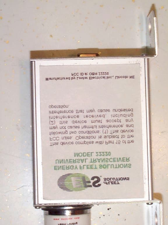
Click to zoom
Application Details
- Equipment Class
- DXT - Part 15 Low Power Transceiver, Rx Verified
- Date of Grant
- Feb 22, 2001
- Application Purpose
- Original Equipment
- Date of Application
- Feb 20, 2001
- Equipment Note
- Universal Transceiver Module
- Frequency Range
- 916.50000000 - 916.50000000
- Country
- United States
Documents & Files
Document Text
Text extracted from the exhibit documents filed with the FCC. Open a document above to read the original.
Users Manual
Operating Instructions 1 31082A UNIVERSAL TRANSCEIVER MODEL 22220 FCC ID #OBH22220 PLEASE SAVE THESE IMPORTANT SAFETY AND OPERATING INSTRUCTIONS For correct operation of the equipment, it is important to read and be familiar with this entire manual before installing and operating the charger. DO NOT DISCARD THIS MANUAL AFTER READING. LOOK FOR THIS SYMBOL TO POINT OUT SAFETY PRECAUTIONS. IT MEANS: BECOME ALERT—YOUR SAFETY IS INVOLVED. IF YOU DO NOT FOLLOW THESE SAFETY INSTRUCTIONS, INJURY OR PROPERTY DAMAGE CAN OCCUR. This device complies with Part 15 of the FCC rules. Operation is subject to the following two conditions: (1) this device may not cause harmful interference, and (2) this device must accept any interference received, including interference that may cause undesired operation. INSTALLATION INSTRUCTIONS Tools needed to install Universal Transceiver Model 22220 and Base Station PC: drill, ¼" drill bit, Phillips screwdriver, ¼ x 5" acid resistant cable ties CAUTION: USE CAUTION WHEN WORKING AROUND BATTERY CHARGING AREAS AND INDUSTRIAL ENVIRONMENTS. ALWAYS WEAR APPROVED PROTECTIVE EYEWEAR. ALWAYS WORK IN A WELL-LIGHTED AREA. WEAR APPROVED SAFETY SHOES. FOLLOW ALL POSTED SAFETY WARNINGS WHEN WORKING ON AND AROUND LADDERS. USE EXTREME CAUTION WHEN OPERATING TOOLS. DO NOT REST TOOLS ON TOP OF MACHINERY OR STORAGE RACK BEAMS. Note: Do not mount the Universal Transceiver where water spills may occur. Do not mount Universal Transceiver on unstable surfaces such as rolling doors, access panels, etc. Do not mount Universal Transceiver where it may be struck by or interfere with the operation of other moving objects, vehicles or other machinery. Never mount the Universal Transceiver near radiators, heating sources or high temperature areas. Never cover or obstruct fire sprinkler systems, access panels, limit switches, circuit breakers, light fixtures or other installed machinery, electronic or mechanical devices. The Universal Transceiver unit has been designed for optimum operation with a clear, unobstructed "Line of Sight" signal transmission range of two hundred feet (200') or less. When mounting the Universal Transceiver, machinery, walls, doors and other physical structures should be avoided in order to achieve maximum antenna performance. ASSEMBLY PROCEDURE – Universal Transceiver 1. Locate a clear wall, ceiling or non-metal rack area to mount the Universal Transceiver. The unit should be mounted at least one foot (1') from metal pipes or racks. Avoid mounting Universal Transceiver near any sources of potential noise interference such as electric motors, fluorescent lamps, radio transmitters, infrared devices, etc. (at least ten feet (10') of clear area is recommended). Line of site Operating Instructions 2 31082A obstructions may interfere with maximum signal strength and reception. 2. Using the Universal Transceiver mounting bracket as a guide, mark two spots to be drilled to support the unit. Use extreme caution to avoid drilling into walls containing wiring or pipes. ASSEMBLY PROCEDURE – Base Station PC 1. Determine a suitable wall or rack location to mount the Base Station PC within twenty-five feet (25') of the Universal Transceiver unit near a standard 110 VAC power supply and approved telephone jack. Use only the supplied hardware brackets when mounting the Base Station PC. Do not drill or tap any holes in the case of the Base Station PC. 2. Attach the RS232 nine-pin cable to the Universal Transceiver. Carefully route this cable to the Base Station PC and attach cable to RS232 receptacle. 3. Secure the RS232 Cable to wall and rack areas using approved cable ties and wall style cable fasteners. Do not allow anything to rest on the Base Station PC or its cables including other signal transmission cables or lines. 4. Attach an approved telecommunications cable to the receptacle port on the rear of the Base Station PC. Neatly secure the cable along its path using approved cable ties. 5. Attach the 110 VAC power cable to the rear of the Base Station PC. Plug the power cable in to the nearest 110 VAC power source. 6. Turn Base Station PC power on using the rocker switch located on the rear of the unit. There are no user serviceable parts in the Universal Transceiver or Base Station PC. Any attempt to access or repair any internal components will void the manufacturer's warranty. For product warranty or customer assistance, please contact Lester Electrical, Inc. at (402) 477-8988. Manufactured by Lester Electrical, Inc. Lincoln, Nebraska
Cover Letter(s)
Manufacturers of Battery Chargers and Electrical Specialties 625 West A Street • • Lincoln, Nebraska 68522-1794 • • Telephone (402) 477-8988 • • FAX (402) 474-1769 February 12, 2001 Federal Communications Commission Authorization & Evaluation Division 7435 Oakland Mills Road Columbia, Maryland 21046 Subject: Type Acceptance Application: FCC ID OBH 22220 and OBH 22240 To Whom It May Concern: DELEGATION OF AUTHORITY Lester Electrical of Nebraska Incorporated hereby authorizes Professional Testing (EMI) Inc. of Round Rock, Texas to operate on its behalf in the matter of FCC approval for the following: Universal Transceiver Module (FCC ID OBH 22220) RF Data Collection Module (FCC ID OBH 22240) Professional Testing is authorized to file the necessary forms, exhibits and fees required to facilitate this application. REQUEST FOR CONFIDENTIALITY Lester Electrical of Nebraska Inc. requests, pursuant to 47CFR0.459, post-grant confidentiality for identified sections of the filing material contained in this application with this material being withheld from public inspection following the grant of this authorization. This material includes Exhibit 4 - block diagram; Exhibit 5 - Schematic Diagram; Exhibit 9 – internal PCB photos and Exhibit 12 - Theory of Operation. These exhibits contain information relating to circuit function and complexity that could be of benefit to competitors, contains trade secrets and confidential information which is not customarily released or made available to the public. If there are further questions, please contact me: Mr. Chuck Langston [email protected] (402) 477-8988 x146 (office) (402) 474-1769 (FAX) __________________________________ Chuck Langston Engineering Product Manager Manufacturers of Battery Chargers and Electrical Specialties 625 West A Street • • Lincoln, Nebraska 68522-1794 • • Telephone (402) 477-8988 • • FAX (402) 474-1769 ANTI-DRUG CERTIFICATION Lester Electrical of Nebraska Incorporated certifies that no party to this application (as defined in 47 C.F.R. §1.2002(b)(2) ) is subject to a denial of federal benefits pursuant to Section 5301 of the Anti-Drug Abuse Act of 1988, 21 U.S.C 853a. ___January 8, 2001 __________ __________________________________ Date Signature __________________________________ Title
External Photos
Professional Testing (EMI), Inc. FCC ID: OBH 22220 Page 1 of 7 Product Photographs Project Number: 01078-10 Prepared for: LESTER ELECTRICAL, INC. 625 West A Street Lincoln, Nebraska 68522-1794 By Professional Testing (EMI), Inc. 1601 FM 1460, Suite B Round Rock, Texas 78664 January 2001 TYPE CERTIFICATION LESTER ELECTRICAL, INC. UNIVERSAL TRANSEIVER Professional Testing (EMI), Inc. FCC ID: OBH 22220 Page 2 of 7 TABLE OF CONTENTS TOP-OBLIQUE VIEW OF UNIT...................................................................................3 TOP VIEW OF UNIT.....................................................................................................4 TOP-OBLIQUE VIEW OF BASESTATION..................................................................5 FRONT VIEW OF BASESTATION...............................................................................6 REAR OF BASESTATION............................................................................................7 Professional Testing (EMI), Inc. FCC ID: OBH 22220 Page 3 of 7 TOP-OBLIQUE VIEW OF UNIT Professional Testing (EMI), Inc. FCC ID: OBH 22220 Page 4 of 7 TOP VIEW OF UNIT Professional Testing (EMI), Inc. FCC ID: OBH 22220 Page 5 of 7 TOP-OBLIQUE VIEW OF BASESTATION Professional Testing (EMI), Inc. FCC ID: OBH 22220 Page 6 of 7 FRONT VIEW OF BASESTATION Professional Testing (EMI), Inc. FCC ID: OBH 22220 Page 7 of 7 REAR OF BASESTATION
ID Label/Location Info
Label for Universal Transceiver (Shown at 200% of actual size.) Professional Testing (EMI), Inc. FCC ID: OBH 22220 Page 3 of 7 TOP-OBLIQUE VIEW OF UNIT
RF Exposure Info
Professional Testing (EMI), Inc. FCC ID: OBH 22220 Page 1 of 2 RF Exposure Evaluation Project Number: 01078-10 Prepared for: LESTER ELECTRICAL, INC. 625 West A Street Lincoln, Nebraska 68522-1794 By Professional Testing (EMI), Inc. 1601 FM 1460, Suite B Round Rock, Texas 78664 January 2001 TYPE CERTIFICATION LESTER ELECTRICAL, INC. UNIVERSAL TRANSEIVER Professional Testing (EMI), Inc. FCC ID: OBH 22220 Page 2 of 2 The Universal Transceiver Module operates under Part 15and is classified as a “Mobile Device” by the guidance given in 47 CFR 2.1091 and OET Bulletin 65, which states: “Transmitting devices designed to be used by consumers or workers that can be easily re-located, such as wireless devices associated with a personal computer and transportable cellular telephones (“bag” phones), are considered to be mobile devices if they meet the 20 centimeter separation requirement.” The Universal Transceiver Module meets this description including the requirement that it be used more than 20 centimeters from the user. “...are subject to routine environmental evaluation for RF exposure use if they operate at frequencies of 1.5 GHz or below and their effective radiated power (ERP) is 1.5 watts or more,...” The Universal Transceiver Module has a typical output power of 0 dBm or 1 mW. The peak, measured power in the fundamental was 90.0 dB (uV/m). Using the formula: P = .3 V 2 The measured power is 0.30 mW in the fundamental. An earlier reading of the fundamental, made without a preamplifier measured a result of 92.9 dB (uV/m), which yields a result of 0.59 mW. This measurement is considered less accurate than the value reported in the test report. However, it is reported here as it give a worst case measurement for this purpose. However, both measurements are clearly well below the requirement. Therefore, a routine environmental evaluation for RF exposure is not required.
Test Report
Project Number: 01078-10 Prepared for: LESTER ELECTRICAL, INC. 625 West A Street Lincoln, Nebraska 68522-1794 By Professional Testing (EMI), Inc. 1601 FM 1460, Suite B Round Rock, Texas 78664 January 2001 TYPE CERTIFICATION TEST REPORT UNIVERSAL TRANSEIVER MODULE Professional Testing (EMI), Inc. FCC ID: OBH 22220 Page 2 of 16 TABLE OF CONTENTS 1. EUT Description...........................................................................................................3 1.1. EUT Operation......................................................................................................4 2. Radiated Emissions Testing..........................................................................................4 2.1. Test Procedure.......................................................................................................4 2.2. Test Criteria...........................................................................................................4 2.3. Test Results...........................................................................................................5 3. Occupied Bandwidth Measurements............................................................................5 3.1. Test Procedure.......................................................................................................5 3.2. Test Criteria...........................................................................................................6 3.3. Test Results...........................................................................................................6 4. Antenna Requirement...................................................................................................6 4.1. Evaluation Procedure............................................................................................6 4.2. Evaluation Criteria................................................................................................6 4.3. Evaluation Results................................................................................................7 5. Conducted Emissions Testing.......................................................................................7 5.1. Test Procedure.......................................................................................................7 5.2. Test Criteria...........................................................................................................7 5.3. Test Results...........................................................................................................8 6. Modifications to Equipment.........................................................................................8 7. List of Test Equipment..................................................................................................8 8. Appendix A: Fundamental Radiated Emissions Data................................................10 9. Appendix B: Spurious Radiated Emissions...............................................................11 9.1. Pre-Scan Graphs..................................................................................................12 10. Appendix C: Occupied Bandwidth.........................................................................14 11. Appendix D: Conducted Emissions........................................................................15 Figures Figure 1: Radiated Emissions Test Setup .......................................................................... 9 THIS REPORT SHALL NOT BE REPRODUCED EXCEPT IN FULL, WITHOUT THE WRITTEN APPROVAL OF PROFESSIONAL TESTING (EMI), INC. Professional Testing (EMI), Inc. FCC ID: OBH 22220 Page 3 of 16 1. EUT Description The Equipment Under Test (EUT) is the Lester Electrical, Inc., Universal Transceiver Module. The Universal Transceiver Module is used together with one or more Data Collection Modules and Temperature Sensor Units for gathering battery performance and vehicle utilization data. The EUT operates in the 902 - 928 MHz band and is designed for compliance with 47 CFR 15.249 of the FCC rules. The Universal Transceiver Module/Base Station consists of a DC to DC converter power supply, microprocessor and RF transceiver constructed entirely of surface mount components attached to a 2.4" X 2.4" PC board, mounted in a metal enclosure with an external, permanently attached antenna. The serial port of the small personal computer to which it is attached powers it. The device employs a bi-directional RF data link to gather data from Data Collection Modules attached to batteries. The device operates at a frequency of 916.5 MHz and employs on-off keying as the modulation method. Data is Manchester encoded and transmitted at an approximate rate of 12Khz. The device operates autonomously and is normally in the receive mode. Periodically, it may transmit a 200-millisecond burst of data to convey status information to Data Collection Modules or to request specific data from them. The Personal computer is a model ILH386V with a 386 processor operating at 25 MHz. The PC contains an internal hard disk drive, a floppy disk drive, a flash disk drive. Specific test requirements for this device include the following: 47 CFR 15.249 Fundamental Transmit Power 47 CFR 15.249 Spurious Radiated Power & 15.205 47 CFR 15.249 Occupied Bandwidth 15.231 & 2.989 (2.989 used as Procedural Reference) 47 CFR 15.203 Antenna Requirement 47 CFR 15.207 Conducted Emissions The system tested consisted of the following: Manufacturer & Model FCC ID # Description Lester Electrical, Inc. OBH22220 Universal Transceiver Module Professional Testing (EMI), Inc. FCC ID: OBH 22220 Page 4 of 16 1.1. EUT Operation The Universal Transceiver Module was tested with the wireless link active and fully modulated. Setup and operational modes cover worst case configuration and operational modes for the device. 2. Radiated Emissions Testing Professional Testing (EMI), Inc. (PTI), follows the guidelines of NIST for all uncertainty calculations, est…
Text truncated - open the document above for the full version.
Test Setup Photos
Professional Testing (EMI), Inc. FCC ID: OBH 22220 Page 1 of 8 Test Set-Up Photographs Project Number: 01078-10 Prepared for: LESTER ELECTRICAL, INC. 625 West A Street Lincoln, Nebraska 68522-1794 By Professional Testing (EMI), Inc. 1601 FM 1460, Suite B Round Rock, Texas 78664 January 2001 TYPE CERTIFICATION LESTER ELECTRICAL, INC. UNIVERSAL TRANSEIVER Professional Testing (EMI), Inc. FCC ID: OBH 22220 Page 2 of 8 TABLE OF CONTENTS CONDUCTED EMISSIONS - FRONT OF UNIT...........................................................3 CONDUCTED EMISSIONS - BACK OF UNIT.............................................................4 RADIATED EMISSIONS - FRONT OF UNIT...............................................................5 RADIATED EMISSIONS - RIGHT-REAR OF UNIT....................................................6 RADIATED EMISSIONS, HIGH FREQ. – FRONT OF UNIT.......................................7 RADIATED EMISSIONS, HIGH FREQ. – REAR OF UNIT.........................................8 Professional Testing (EMI), Inc. FCC ID: OBH 22220 Page 3 of 8 CONDUCTED EMISSIONS - FRONT OF UNIT Professional Testing (EMI), Inc. FCC ID: OBH 22220 Page 4 of 8 CONDUCTED EMISSIONS - BACK OF UNIT Professional Testing (EMI), Inc. FCC ID: OBH 22220 Page 5 of 8 RADIATED EMISSIONS - FRONT OF UNIT Professional Testing (EMI), Inc. FCC ID: OBH 22220 Page 6 of 8 RADIATED EMISSIONS - RIGHT-REAR OF UNIT Professional Testing (EMI), Inc. FCC ID: OBH 22220 Page 7 of 8 RADIATED EMISSIONS, HIGH FREQ. – FRONT OF UNIT Professional Testing (EMI), Inc. FCC ID: OBH 22220 Page 8 of 8 RADIATED EMISSIONS, HIGH FREQ. – REAR OF UNIT
Contact Information
Applicant
Spencer Stock(President)
Technical Contact
Communication CertificationScott B Earl
[email protected]801.972.6146
1940 W. Alexander Street · Salt Lake City, Utah · United States
Test Firm
Professional Testing (EMI), Inc.Jeff Link
Technical Specifications
| # | Rule Parts | Frequency Range | Power Output |
|---|---|---|---|
| 1 | 15C | 916.5 MHz - 916.5 MHz | - |
Other Applications from Lester Electrical of Nebraska Inc
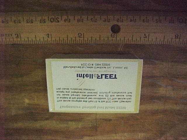
OBH22250
Jul 06, 2001Wireless Temperature Sensor
Equipment Class
DXX - Part 15 Low Power Communication Device Transmitter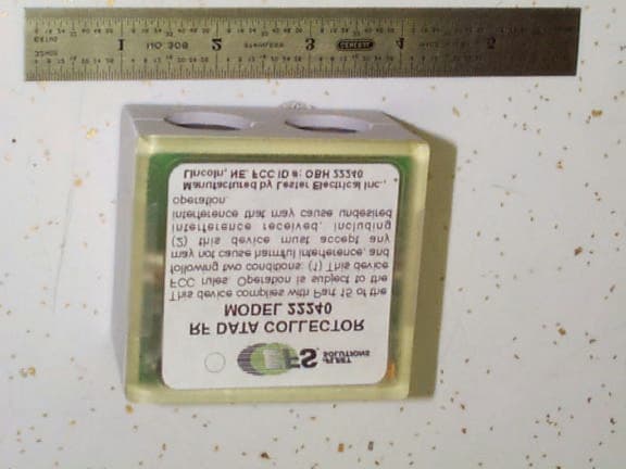
OBH22240
Feb 27, 2001Data Collection Module
Equipment Class
DXT - Part 15 Low Power Transceiver, Rx Verified
OBH21820
Mar 30, 1999DXT - Part 15 Low Power Transceiver, Rx Verified
Equipment Class
DXT - Part 15 Low Power Transceiver, Rx Verified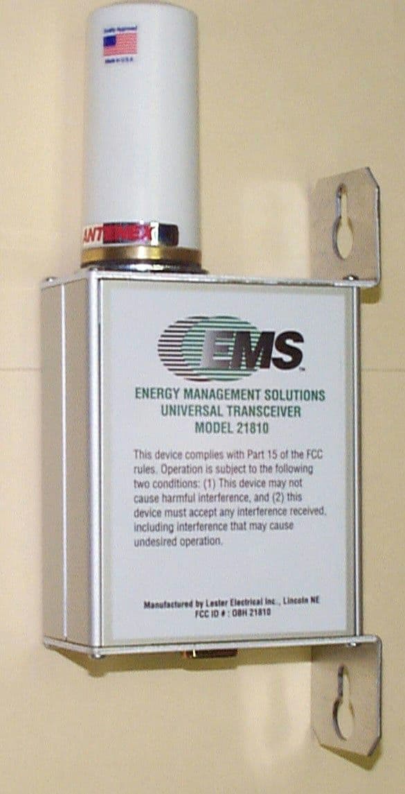
OBH21810
Mar 30, 1999DXT - Part 15 Low Power Transceiver, Rx Verified
Equipment Class
DXT - Part 15 Low Power Transceiver, Rx Verified