OBH22240Data Collection Module
Lester Electrical of Nebraska Inc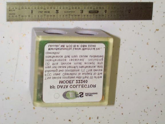
Click to zoom
Application Details
- Equipment Class
- DXT - Part 15 Low Power Transceiver, Rx Verified
- Date of Grant
- Feb 27, 2001
- Application Purpose
- Original Equipment
- Date of Application
- Feb 21, 2001
- Equipment Note
- Data Collection Module
- Frequency Range
- 916.50000000 - 916.50000000
- Country
- United States
Documents & Files
Document Text
Text extracted from the exhibit documents filed with the FCC. Open a document above to read the original.
Users Manual
Operating Instructions 1 31083A RF DATA COLLECTOR MODEL 22240 FCC ID #OBH22240 PLEASE SAVE THESE IMPORTANT SAFETY AND OPERATING INSTRUCTIONS For correct operation of the equipment, it is important to read and be familiar with this entire manual before installing and operating the charger. DO NOT DISCARD THIS MANUAL AFTER READING. LOOK FOR THIS SYMBOL TO POINT OUT SAFETY PRECAUTIONS. IT MEANS: BECOME ALERT—YOUR SAFETY IS INVOLVED. IF YOU DO NOT FOLLOW THESE SAFETY INSTRUCTIONS, INJURY OR PROPERTY DAMAGE CAN OCCUR. This device complies with Part 15 of the FCC rules. Operation is subject to the following two conditions: (1) this device may not cause harmful interference, and (2) this device must accept any interference received, including interference that may cause undesired operation. INSTALLATION INSTRUCTIONS Tools needed to install RF Data Collector Model 22240: 11/32" nut driver, Phillips screwdriver, Anderson Connector-Terminal Cable extractor CAUTION: USE CAUTION WHEN WORKING WITH INDUSTRIAL BATTERIES; THEY CAN BE VERY DANGEROUS. INDUSTRIAL BATTERIES CONTAIN ACID (ELECTROLYTE SOLUTION) WHICH CAN CAUSE CHEMICAL BURNS AND SERIOUS HARM TO SKIN AND EYES. ALWAYS WEAR APPROVED PROTECTIVE EYE GOGGLES AND RUBBER GLOVES. AVOID PROLONGED BREATHING OF BATTERY VAPORS; WORK IN A WELL-VENTILATED AREA. BATTERY VAPORS CAN BE FLAMMABLE. DO NOT REST TOOLS ON TOP OF BATTERY OR ALLOW ANY METAL OBJECTS TO COME IN CONTACT WITH BATTERY POSTS OR INTER-CELL CONNECTORS. ASSEMBLY PROCEDURE 1. Examine the cables between the battery and DC plug. With caution, use the Anderson Terminal- Cable extractor to remove only the positive (RED) battery cable contact from the battery DC plug housing. 2. From the RF Data Collector case assembly, remove the bottom half of the case and the plastic cord clamping device. 3. Carefully slide the positive (RED) cable contact through the BLUE ring toroid, located in the top half of case, with the ring "end" of the Data Collector facing the battery. Reposition the RED cable contact inside the battery DC plug housing. Locate the RF Data Collector case top (with LED facing up) close to the DC plug housing and outside of all metal enclosures. 4. Lay the negative (BLACK) battery cable in the area provided next to the positive (RED) cable. 5. Position the plastic battery cable clamp over both of the wires so that the clamp slides easily over the studs located in the RF Data Collector. Verify that the arrows on top of the clamp point toward the BLUE ring/battery end of the cables. 6. Using hand pressure only, carefully exert downward force on the plastic battery cable clamp until enough of the studs protrude through the clamp to allow starting the hex nuts. Operating Instructions 2 31083A 7. Tighten the hex nuts evenly. Never exceed 30 pound-inches of torque on the nuts. Failure to tighten the nuts evenly or overtightening can cause loss of electrical connection, part breakage, or cable damage. 8. Assemble the bottom cover to the unit. 9. Insert the four cover screws in the holes provided. Do not overtighten. OPERATIONAL INSTRUCTIONS – RF Data Collector Model 22240 10. The LED located on top of the RF Data Collector should be blinking from RED to GREEN rapidly, indicating a proper installation. If the LED does not blink, verify the polarity of connections to determine the cause. 11. During normal operation of the battery, the LED on the RF Data Collector will blink RED, indicating a run or discharge condition. The LED will blink GREEN while the battery is being charged. There are no user serviceable parts in the Universal Transceiver or Base Station PC. Any attempt to access or repair any internal components will void the manufacturer's warranty. For product warranty or customer assistance, please contact Lester Electrical, Inc. at (402) 477-8988. Manufactured by Lester Electrical, Inc. Lincoln, Nebraska
Attestation Statements
Certificate of Compliance ______________________________ Applicant: Lester Electrical, Inc. Applicant’s Address: 625 West A Street Lincoln, Nebraska 68522 Model: Data Collection Module Serial Number: N/A Project Number: 01076-10 Test Dates: August 14-21, 2000 I, Jeffrey A. Lenk, for Professional Testing (EMI), Inc., being familiar with the FCC rules and test procedures have reviewed the test setup, measured data and this report. I believe them to be true and accurate. The Lester Electrical, Inc. Data Collection Module was tested to and found to be in compliance with FCC Part 15 Subpart C for an Intentional Radiator. The highest emissions generated by the above equipment are listed below: Frequency (MHz) Level (dB ìV/m) Limit (dB ìV/m) Margin (dB) Fundamental 916.5 90.1 93.9 - 3.8 Spurious 1832.2 38.9 53.9 - 15.0 Spurious 2749.6 39.2 53.9 - 14.7 Occupied Bandwidth Record Only Per 47 CFR 15 - Widest OCBW: 120 kHz ______________________________ Jeffrey A. Lenk President This report has been reviewed and accepted by Lester Electrical, Inc. The undersigned is responsible for ensuring that the Data Collection Module will continue to comply with the FCC rules. 1601 F M 1460, Suite B, Round Rock , Texas 78664 5 1 2 /2 4 4 -3 3 7 1 F a x 5 1 2 /2 4 4 -1 8 4 6
Cover Letter(s)
Manufacturers of Battery Chargers and Electrical Specialties 625 West A Street • • Lincoln, Nebraska 68522-1794 • • Telephone (402) 477-8988 • • FAX (402) 474-1769 February 12, 2001 Federal Communications Commission Authorization & Evaluation Division 7435 Oakland Mills Road Columbia, Maryland 21046 Subject: Type Acceptance Application: FCC ID OBH 22220 and OBH 22240 To Whom It May Concern: DELEGATION OF AUTHORITY Lester Electrical of Nebraska Incorporated hereby authorizes Professional Testing (EMI) Inc. of Round Rock, Texas to operate on its behalf in the matter of FCC approval for the following: Universal Transceiver Module (FCC ID OBH 22220) RF Data Collection Module (FCC ID OBH 22240) Professional Testing is authorized to file the necessary forms, exhibits and fees required to facilitate this application. REQUEST FOR CONFIDENTIALITY Lester Electrical of Nebraska Inc. requests, pursuant to 47CFR0.459, post-grant confidentiality for identified sections of the filing material contained in this application with this material being withheld from public inspection following the grant of this authorization. This material includes Exhibit 4 - block diagram; Exhibit 5 - Schematic Diagram; Exhibit 9 – internal PCB photos and Exhibit 12 - Theory of Operation. These exhibits contain information relating to circuit function and complexity that could be of benefit to competitors, contains trade secrets and confidential information which is not customarily released or made available to the public. If there are further questions, please contact me: Mr. Chuck Langston [email protected] (402) 477-8988 x146 (office) (402) 474-1769 (FAX) __________________________________ Chuck Langston Engineering Product Manager Manufacturers of Battery Chargers and Electrical Specialties 625 West A Street • • Lincoln, Nebraska 68522-1794 • • Telephone (402) 477-8988 • • FAX (402) 474-1769 ANTI-DRUG CERTIFICATION Lester Electrical of Nebraska Incorporated certifies that no party to this application (as defined in 47 C.F.R. §1.2002(b)(2) ) is subject to a denial of federal benefits pursuant to Section 5301 of the Anti-Drug Abuse Act of 1988, 21 U.S.C 853a. ___January 8, 2001 __________ __________________________________ Date Signature __________________________________ Title
External Photos
Professional Testing (EMI), Inc. FCC ID: OBH 22240 Page 1 of 2 Product Photographs Project Number: 01076-10 Prepared for: LESTER ELECTRICAL, INC. 625 West A Street Lincoln, Nebraska 68522-1794 By Professional Testing (EMI), Inc. 1601 FM 1460, Suite B Round Rock, Texas 78664 January 2001 TYPE CERTIFICATION LESTER ELECTRICAL, INC. DATA COLLECTION MODULE Professional Testing (EMI), Inc. FCC ID: OBH 22240 Page 2 of 2 = TOP-OBLIQUE VIEW OF UNIT
ID Label/Location Info
Label for RF Data Collector (Shown at 200% of actual size.) Professional Testing (EMI), Inc. FCC ID: OBH 22240 Page 2 of 2 = TOP-OBLIQUE VIEW OF UNIT
RF Exposure Info
Professional Testing (EMI), Inc. FCC ID: OBH 22240 Page 1 of 2 RF Exposure Evaluation Project Number: 01076-10 Prepared for: LESTER ELECTRICAL, INC. 625 West A Street Lincoln, Nebraska 68522-1794 By Professional Testing (EMI), Inc. 1601 FM 1460, Suite B Round Rock, Texas 78664 January 2001 TYPE CERTIFICATION LESTER ELECTRICAL, INC. DATA COLLECTION MODULE Professional Testing (EMI), Inc. FCC ID: OBH 22240 Page 2 of 2 The Data Collection Module operates under Part 15 and is classified as a “Mobile Device” by the guidance given in 47 CFR 2.1091 and OET Bulletin 65, which states: “Transmitting devices designed to be used by consumers or workers that can be easily re-located, such as wireless devices associated with a personal computer and transportable cellular telephones (“bag” phones), are considered to be mobile devices if they meet the 20 centimeter separation requirement.” The Data Collection Module meets this description including the requirement that it be used more than 20 centimeters from the user. “...are subject to routine environmental evaluation for RF exposure use if they operate at frequencies of 1.5 GHz or below and their effective radiated power (ERP) is 1.5 watts or more,...” The Data Collection Module has a typical output power of 0 dBm or 1 mW. The peak, measured power in the fundamental was 90.1 dB (uV/m). Using the formula: P = .3 V 2 The measured power is 0.307 mW in the fundamental. An earlier reading of the fundamental, made without a preamplifier measured a result of 93 dB (uV/m), which yields a result of 0.60 mW. This measurement is considered less accurate than the value reported in the test report. However, it is reported here as it give a worst case measurement for this purpose. However, both measurements are clearly well below the requirement. Therefore, a routine environmental evaluation for RF exposure is not required.
Test Report
Project Number: 01076-10 Prepared for: LESTER ELECTRICAL, INC. 625 West A Street Lincoln, Nebraska 68522-1794 By Professional Testing (EMI), Inc. 1601 FM 1460, Suite B Round Rock, Texas 78664 January 2001 TYPE CERTIFICATION TEST REPORT DATA COLLECTION MODULE Professional Testing (EMI), Inc. FCC ID: OBH 22240 Page 2 of 12 TABLE OF CONTENTS 1. EUT Description...........................................................................................................3 1.1. EUT Operation......................................................................................................3 2. Radiated Emissions Testing..........................................................................................3 2.1. Test Procedure.......................................................................................................4 2.2. Test Criteria...........................................................................................................4 2.3. Test Results...........................................................................................................5 3. Occupied Bandwidth Measurements............................................................................5 3.1. Test Procedure.......................................................................................................5 3.2. Test Criteria...........................................................................................................5 3.3. Test Results...........................................................................................................6 4. Antenna Requirement...................................................................................................6 4.1. Evaluation Procedure............................................................................................6 4.2. Evaluation Criteria................................................................................................6 4.3. Evaluation Results................................................................................................6 5. Modifications to Equipment.........................................................................................6 6. List of Test Equipment..................................................................................................7 7. Appendix A: Fundamental Radiated Emissions Data..................................................9 8. Appendix B: Spurious Radiated Emissions...............................................................10 9. Appendix C: Occupied Bandwidth.............................................................................12 Figures Figure 1: Radiated Emissions Test Setup .......................................................................... 9 THIS REPORT SHALL NOT BE REPRODUCED EXCEPT IN FULL, WITHOUT THE WRITTEN APPROVAL OF PROFESSIONAL TESTING (EMI), INC. Professional Testing (EMI), Inc. FCC ID: OBH 22240 Page 3 of 12 1. EUT Description The Equipment Under Test (EUT) is the Lester Electrical, Inc., Data Collection Module. The Data Collection Module is used together with a Universal Transceiver Module attached to a base station and Temperature Sensor Units for gathering battery performance and vehicle utilization data. The EUT operates in the 902 - 928 MHz band and is designed for compliance with 47 CFR 15.249 of the FCC rules. The data collection Module consists of a DC to DC converter power supply, microprocessor and RF transceiver constructed entirely of surface mount components attached to a 2.4" X 2.4" PC board. It is a battery-powered device that gathers battery performance data from the battery to which it is attached. The device operates at a frequency of 916.5 MHz and employs on-off keying as the modulation method. It has a typical output power of 0 dBm and a maximum power of 5 dBm. Data is Manchester encoded and transmitted at an approximate rate of 12Khz. The device operates autonomously and transmits a 200 millisecond burst of data once every 5 to 8 minutes. Specific test requirements for this device include the following: 47 CFR 15.249 Fundamental Transmit Power 47 CFR 15.249 Spurious Radiated Power & 15.205 47 CFR 15.249 Occupied Bandwidth 15.231 & 2.989 (2.989 used as Procedural Reference) 47 CFR 15.203 Antenna Requirement The system tested consisted of the following: Manufacturer & Model FCC ID # Description Lester Electrical, Inc. OBH22240 Data Collection Module 1.1. EUT Operation The Data Collection Module was tested with the wireless link active and fully modulated. Setup and operational modes cover worst case configuration and operational modes for the device. 2. Radiated Emissions Testing Professional Testing (EMI), Inc. (PTI), follows the guidelines of NIST for all uncertainty calculations, estimates and expressions thereof for EMC testing. Professional Testing (EMI), Inc. FCC ID: OBH 22240 Page 4 of 12 Radiated emission measurements were made of the Fundamental and Spurious Emission levels for the Data Collection Module. Measurements of the occupied bandwidth were also made for the equipment. Measurements of the maximum emission levels for the fundamental and the spurious/harmonic emissions of the Data Collection Module were made at the Professional Testing "Open Field" Site 3, located in Round Rock, Texas to determine the radio noise radiated from the EUT. A “Description of Measurement Facilities” has been submitted to the FCC and approved pursuant to Section 2.948 of CFR 47 of the FCC rules. Tests of the fundamental for the device were performed to determine the worst case polarization of the devices. The fundamental emissions of the device were measured with the antennas of the devices vertical and horizontal to the ground plane. 2.1. Test Procedure The EUT was placed on a non-conductive table 0.8 meters above the ground plane. The table was centered on a motorized turntable which allows 360 degree rotation. For measurements of the fundamental signal, a measurement antenna was positioned at a dista…
Text truncated - open the document above for the full version.
Test Setup Photos
Professional Testing (EMI), Inc. FCC ID: OBH 22240 Page 1 of 6 Test Set-Up Photographs Project Number: 01076-10 Prepared for: LESTER ELECTRICAL, INC. 625 West A Street Lincoln, Nebraska 68522-1794 By Professional Testing (EMI), Inc. 1601 FM 1460, Suite B Round Rock, Texas 78664 January 2001 TYPE CERTIFICATION LESTER ELECTRICAL, INC. DATA COLLECTION MODULE Professional Testing (EMI), Inc. FCC ID: OBH 22240 Page 2 of 6 TABLE OF CONTENTS RADIATED EMISSIONS - FRONT OF UNIT...............................................................3 RADIATED EMISSIONS - BACK OF UNIT.................................................................4 RADIATED EMISSIONS PRE-SCAN - FRONT OF UNIT...........................................5 RADIATED EMISSIONS PRE-SCAN - REAR OF UNIT.............................................6 Professional Testing (EMI), Inc. FCC ID: OBH 22240 Page 3 of 6 RADIATED EMISSIONS - FRONT OF UNIT Professional Testing (EMI), Inc. FCC ID: OBH 22240 Page 4 of 6 RADIATED EMISSIONS - BACK OF UNIT Professional Testing (EMI), Inc. FCC ID: OBH 22240 Page 5 of 6 RADIATED EMISSIONS PRE-SCAN - FRONT OF UNIT Professional Testing (EMI), Inc. FCC ID: OBH 22240 Page 6 of 6 RADIATED EMISSIONS PRE-SCAN - REAR OF UNIT
Contact Information
Applicant
Spencer Stock(President)
Technical Contact
Lester Electrical, Inc.Chuck Langston
[email protected]402-477-8988
625 West "A" Street · Lincoln, Nebraska · United States
Non-Technical Contact
Lester Electrical, Inc.Chuck Langston
[email protected]402-477-8988
Test Firm
Professional Testing (EMI), Inc.Jeff Link
Technical Specifications
| # | Rule Parts | Frequency Range | Power Output |
|---|---|---|---|
| 1 | 15C | 916.5 MHz - 916.5 MHz | - |
Other Applications from Lester Electrical of Nebraska Inc
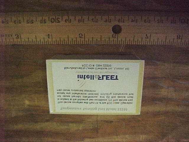
OBH22250
Jul 06, 2001Wireless Temperature Sensor
Equipment Class
DXX - Part 15 Low Power Communication Device Transmitter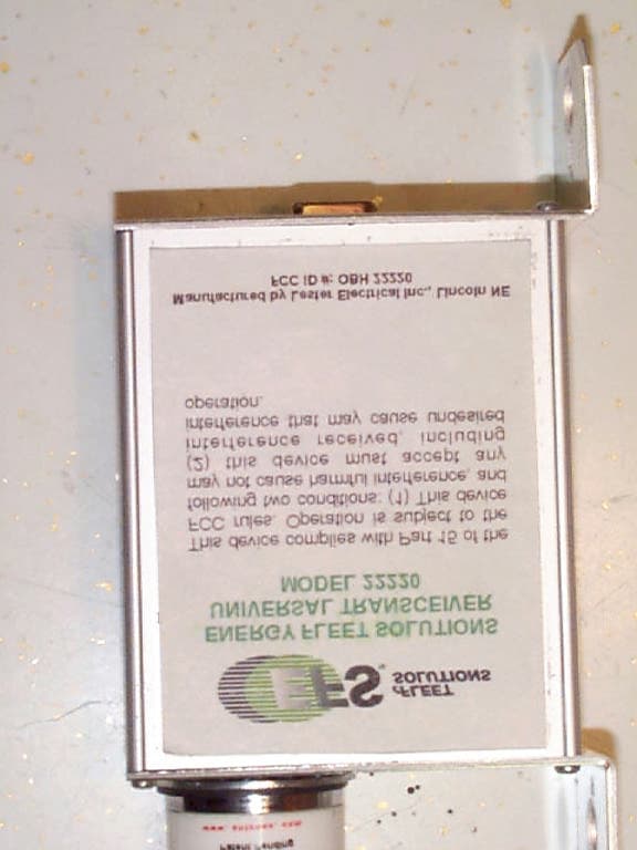
OBH22220
Feb 22, 2001Universal Transceiver Module
Equipment Class
DXT - Part 15 Low Power Transceiver, Rx Verified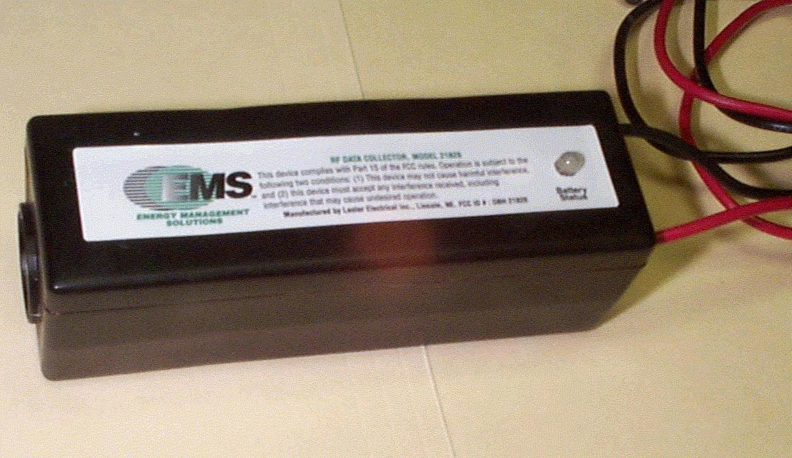
OBH21820
Mar 30, 1999DXT - Part 15 Low Power Transceiver, Rx Verified
Equipment Class
DXT - Part 15 Low Power Transceiver, Rx Verified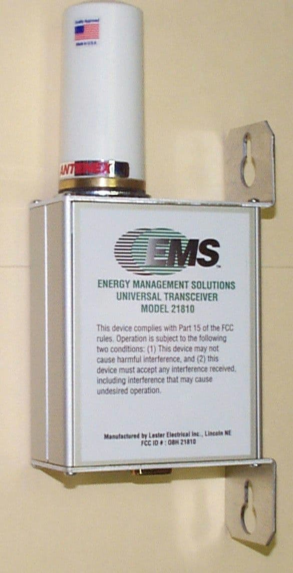
OBH21810
Mar 30, 1999DXT - Part 15 Low Power Transceiver, Rx Verified
Equipment Class
DXT - Part 15 Low Power Transceiver, Rx Verified