OCMPRESTOPADSER01
Presto Technologies Inc.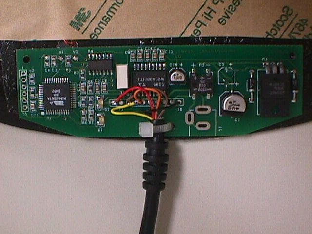
Click to zoom
Application Details
- Equipment Class
- DCD - Part 15 Low Power Transmitter Below 1705 kHz
- Date of Grant
- Jul 25, 1999
- Application Purpose
- Original Equipment
- Date of Application
- Jun 02, 1999
- Frequency Range
- 0.12500000 - 0.12500000
- Company
- Presto Technologies Inc.
- Country
- United States
Documents & Files
Document Text
Text extracted from the exhibit documents filed with the FCC. Open a document above to read the original.
ID Label/Location Info
2.0PRODUCT LABELING FIGURE 1: FCC LABEL This device complies with the FCC, part 15 rules. Operation is subject to the following two conditions: 1) This device may not cause harmful interference. 2) This device must accept any interference received, including interference that may cause undesired operation. FCC ID: OCMPRESTOPADSER01 FIGURE 2: LOCATION OF LABEL ON EUT ← Back of RFID Mousepad Location of Label
Internal Photos
FIGURE 3: RFID Mousepad Transmitter, Front (Game Port Configuration) FIGURE 4: RFID Mousepad Transmitter, Back (Game Port Configuration) FIGURE 5: PrestoPad Mousepad Transmitter, Front (Serial Port Configuration) FIGURE 6: PrestoPad Mousepad, Back (Serial Port Configuration) FIGURE 7: Top Side Mousepad Housing FIGURE 8: Inductive Antenna FIGURE 9: Mousepad Housing FIGURE 10: Component Side, Game Port Connection FIGURE 11: Solder Side, Game Port Connection FIGURE 12: Game Port Connector FIGURE 13: Component Side, Serial Connection FIGURE 14: Solder Side, Serial Connection FIGURE 15: DB9 Serial Port Connector FIGURE 16: Top Side AC/DC Wall Transformer FIGURE 17: Bottom Side AC/DC Wall Transformer FIGURE 18: Inductive Antenna FIGURE 19: Transponder Side A FIGURE 20: Transponder Side B
Schematics
+5 VDC Game Port ID CMOS Transmit CMOS Receive RS-232 Transmit RS-232 Receive AC adapter 1 AC adapter 2 Ground 1 2 3 4 5 6 7 8 9 10 11 12 13 14 15 1 2 3 4 5 6 7 8 9 10 +5 VDC +5 VDC +5 VDC RS-232 Transmit CMOS Transmit CMOS Receive RS-232 Receive Game Port ID Ground AC adapter 1 AC adapter 2 1 2 3 4 5 6 7 8 9 10 11 12 13 14 15 +5 VDC +5 VDC +5 VDC CMOS Transmit CMOS Receive Game Port ID Ground +5 VDC Game Port ID CMOS Transmit CMOS Receive RS-232 Transmit RS-232 Receive AC adapter 1 AC adapter 2 Ground 1 3 4 5 6 7 8 9 10 Signal NamePCB pin # DB-15 Male Game Port pin # 1,8,9 4 15 12 2 6 11 13 5 Wire color Full Feature Game Port Cable +5 VDC Game Port ID CMOS Transmit CMOS Receive Ground 1 3 4 5 10 Signal NamePCB pin # DB-15 Male Game Port pin # 1,8,9 4 15 12 5 Wire color Simple Game Port Cable (no serial support) RS-232 Transmit RS-232 Receive Ground 6 7 10 Signal NamePCB pin # DB-9 Female Serial Port pin # 2 3 5 Wire color Serial-only Cable RS-232 Transmit RS-232 Receive Ground 2 6 5 Signal NameDB-15 Female Game Port pin # DB-9 Female Serial Port pin # 2 3 5 Wire color Game Port to Serial Adapter 1 2 3 4 5 6 7 8 9 DB-15 Male Simple Game Port Cable DB-15 Male Full Game Port Cable PCB Cable Connection AC Adapter 111 AC Adapter 213 RS-232 Transmit RS-232 Receive Ground DB-9 Female Serial Port Cable Gameport and Serial Mouse Pad Cable Connections Jeff Mock 1859 Scott St. San Francisco, CA 94115 415 346-2829 415 346-2830 FAX [email protected] 1/25/99 AC Adapter 18 AC Adapter 29
Schematics
55 44 33 22 11 D D C C B B A A Place close to pin 14 Release JCM Jeff Mock1859 Scott St.San Francisco, CA 94115415 346-2829415 346-2830 [email protected](c) 1998 Stuff for AC adapter power Stuff for RS-232 version LEDs for development only Device Programming Cable Connection +5 VDCNCGame Port ID-CMOS TransmitCMOS ReceiveRS232 TransmitRS232 ReceiveAC adapterAC adapterGround 01 S0 Presto Technologies Serial Mouse Pad 11 Wednesday, January 27, 1999 TitleSize Document Number Rev Date: Sheet of A1A2 SCKDIN PSCKMOSI VDD ID0ID1AC1AC2RS232RXRS232TX RESET-MISO RXTX RS232EN LED0LED1 CLK DOUT VDD VDD VDD VDD VDD VDD VDD VDD VDD VDD VDD VDD R3100K 1 2 R715 1 2 C50.1uF 12 C60.1uF 12 C33900 1 2 C120.1uF 12 C130.1uF 12 TP1TP 1 TP C4390 1 2 + C10 10uF/25V 12 TP2TP 1 TP U4HTRC110 4214 1 1213 59 10 83 67 TX1TX2 RX GNDCEXTQGNDMODEDINDOUTSCKVDD XTAL1XTAL2 X14 MHZ 1 3 2 X1 X2 GND R4 1.5K 12 R1180 1 2 R2180 1 2 J2CONN6 123456 P1P2P3P4P5P6 U3AT90S4414QUAD.80M/44/WG12.00 3736353433323130 4 1638151427 57 3218 29 1819202122232425 4041424344 910111213 26 PA0PA1PA2PA3PA4PA5PA6PA7 RESET-GNDVDDXTAL1XTAL2ALE RXD TXD SCKMISOMOSIINT0ICP PC0PC1PC2PC3PC4PC5PC6PC7 PB0PB1PB2PB3PB4 PD3PD4PD5PD6PD7 OC1B R51.5K 12 R61.5K 12 PWR 123 PI PO PS + C1 47uF/35V 12 D41N4001 12 + C2 10uf/25V 12 R81.5K 12 J3CONN10 123456789 10 P1P2P3P4P5P6P7P8P9P10 R91.5K 12 C80.1uf 12 C140.1uf 12 C110.1uF 12 U5LT1180A 37 161718 24 158149 56 10131112 VP VM GNDVDDONC1PC1M RS232OUT1RS232OUT2 RS232IN1RS232IN2 C2PC2MLOUT2LOUT1LIN2LIN1 C70.1uf 1 2 C90.1uf 1 2 U2BRIDGE 34 12 AC1AC2 P M D21N4001 1 2 U178M05 1 3 2 IN OUT GND D1LED A C D3LED A C
Test Report
APPLICATION FOR FCC CERTIFICATION CLASS B TRANSMITTER DEVICE Presto Technologies, Inc. 110 Pulpit Hill Road Amherst, MA 01002 413-549-8780 MODEL: PrestoPad RFID Mousepad Transmitter (Serial & Game Ports) FCC ID: OCMPRESTOPADSER01 April 29, 1999 REPORT PREPARED BY: EMI Technician:Daniel W. Baltzell Administrative Writer:Dixie L. Shetter Rhein Tech Laboratories, Inc. Document Number: 990215 Reference: QRTL99-092 No part of this report may be reproduced without the full written approval of Rhein Tech Laboratories, Inc. This report concerns (check one):Original Grant: X Class II Change: Equipment Type: Transmitter Deferred grant requested per 47 CFR 0.457 (d) (1) (ii)?Yes:No: X If yes, defer until: Date Company name agrees to notify the Commission by: (date) of the intended date of announcement of the product so that the grant can be issued on that date. Transition Rules Request per 15.37?Yes:No: X If no, assumed Part 15, subpart B for unintentional radiators - the new 47 CFR [10-1-90 Edition] provision.. Page 2 of 41 Document Number: 990215 TABLE OF CONTENTS 1.0GENERAL INFORMATION.................................................................................................................4 1.1RELATED SUBMITTAL(S)/GRANT(S)........................................................................................................4 1.2PRODUCT DESCRIPTION..........................................................................................................................5 1.3TEST SYSTEM DETAILS...........................................................................................................................6 1.4CONFIGURATION OF TESTED SYSTEM (SERIAL PORT)...............................................................................7 1.5CONFIGURATION OF TESTED SYSTEM (GAME PORT)................................................................................8 1.6TEST METHODOLOGY............................................................................................................................9 1.7TEST FACILITY.......................................................................................................................................9 2.0PRODUCT LABELING.......................................................................................................................10 3.0SYSTEM TEST CONFIGURATION..................................................................................................11 3.1JUSTIFICATION.....................................................................................................................................11 3.2EUT EXERCISE SOFTWARE...................................................................................................................11 3.3SPECIAL ACCESSORIES.........................................................................................................................11 3.4MODULATED BANDWIDTH....................................................................................................................11 3.5CONFORMANCE STATEMENT.................................................................................................................12 4.0MEASUREMENT PHOTOS................................................................................................................16 4.1CONDUCTED MEASUREMENT PHOTOS (SERIAL PORT CONFIGURATION)........................................16 4.2CONDUCTED MEASUREMENT PHOTOS (GAME PORT CONFIGURATION)..........................................17 4.3RADIATED MEASUREMENT PHOTOS (SERIAL PORT CONFIGURATION.......................................................18 4.4RADIATED MEASUREMENT PHOTOS (GAME PORT CONFIGURATION).......................................................19 5.0CONDUCTED EMISSION DATA.......................................................................................................20 6.0RADIATED EMISSION DATA...........................................................................................................22 6.1FIELD STRENGTH CALCULATION...........................................................................................................25 7.0PHOTOS OF EUT................................................................................................................................26 APPENDIX LISTING APPENDIX A: SCHEMATICS OF PRESTOPAD RFID MOUSEPAD TRANSMITTER..................................13 APPENDIX B: EMISSIONS EQUIPMENT LIST......................................................................................................35 APPENDIX C: CONDUCTED AND RADIATED TEST METHODOLOGY....................................................................36 APPENDIX D: PLOTS......................................................................................................................................37 APPENDIX E: USER’S MANUAL..................................................................................................................41 Page 3 of 41 Document Number: 990215 FIGURE INDEX FIGURE 1: FCC LABEL....................................................................................................................................10 FIGURE 2: LOCATION OF LABEL ON EUT..........................................................................................................10 FIGURE 3: RFID MOUSEPAD TRANSMITTER, FRONT (GAME PORT CONFIGURATION).........................................26 FIGURE 4: RFID MOUSEPAD TRANSMITTER, BACK (GAME PORT CONFIGURATION)...........................................26 FIGURE 5: PRESTOPAD MOUSEPAD TRANSMITTER, FRONT (SERIAL PORT CONFIGURATION)...............................27 FIGURE 6: PRESTOPAD MOUSEPAD, BACK (SERIAL PORT CONFIGURATION).......................................................27 FIGURE 7: TOP SIDE MOUSEPAD HOUSING........................................................................................................28 FIGURE 8: INDUCTIVE ANTENNA..…
Text truncated - open the document above for the full version.
Test Report
FIGURE 21: Serial Configuration occupied bandwidth Plot FIGURE 22: Game Port configuration occupied bandwidth Plot FIGURE 23: Game Port configuration fundamental Plot
Test Setup Photos
4.0MEASUREMENT PHOTOS 4.1CONDUCTED MEASUREMENT PHOTOS (SERIAL PORT CONFIGURATION) 4.2CONDUCTED MEASUREMENT PHOTOS (GAME PORT CONFIGURATION) 4.3RADIATED MEASUREMENT PHOTOS (SERIAL PORT CONFIGURATION) 4.4RADIATED MEASUREMENT PHOTOS (GAME PORT CONFIGURATION)
Contact Information
Applicant
Daniel Nachbor(President)
413-549-8780
Technical Contact
Rhein Tech Laboratories, Inc.Desmond A Fraser
[email protected]703-689-0368
360 Herndon Parkway, Suite 1400 · Herndon, Virginia · United States
Non-Technical Contact
Rhein Tech Laboratories, Inc.Dixie L Shetter
[email protected]703-689-0368
Technical Specifications
| # | Rule Parts | Frequency Range | Power Output |
|---|---|---|---|
| 1 | 15C | 0.125 MHz - 0.125 MHz | - |
Other Applications from Presto Technologies Inc.

OCMPRESTOPADUSB02
Oct 03, 1999RF MOUSEPAD
Equipment Class
DCD - Part 15 Low Power Transmitter Below 1705 kHz