OD5RP100PROXIMITY READER
Cansec Systems Ltd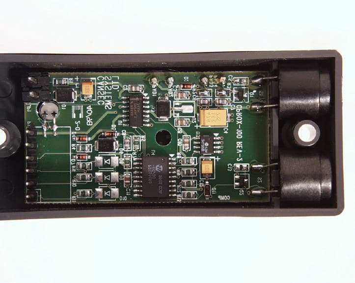
Click to zoom
Application Details
- Equipment Class
- DCD - Part 15 Low Power Transmitter Below 1705 kHz
- Date of Grant
- Mar 10, 1999
- Application Purpose
- Original Equipment
- Date of Application
- Jan 25, 1999
- Equipment Note
- PROXIMITY READER
- Frequency Range
- 0.12500000 - 0.12500000
- Company
- Cansec Systems Ltd
- Country
- Canada
Documents & Files
Document Text
Text extracted from the exhibit documents filed with the FCC. Open a document above to read the original.
Attestation Statements
January 29, 1999 Federal Communications Commission FCC Laboratory Columbia, MD Dear Mr. or Ms., Cansec Systems Ltd. has integrated the electronics board portion of the HID Corporation 6005/8A ProxPoint proximity reader into their product, which has been submitted to you for Part 15 Intentional Radiator Certification. The 6005/8A ProxPoint has FCC Certification under ID No. JQ660XX. The board level reader HID will be selling to Cansec is called the 4065/8A ProxPoint OEM Module. The electronics board for both readers are identical. Cansec has developed their own antenna, which is remote from the electronics board. Because we desire to keep certain documentation for the 6005/8A ProxPoint confidential and not reveal it to Cansec, we are submitting it directly to you. Needless to say, the Cansec application needs to be confidential also. In addition to this letter we are sending you, electronically, the 6005/8A schematic and transmitter block diagram. Also being sent is the 6005/8A technical report, which contains confidentiality request, description of circuit functions, how the device operates, and ground system. Regards, Frank de Vall HID Corporation HID Engineering Center 11674 N. Huron St. Denver, CO 80234-2924 303-453-4033 303-453-4058 fax [email protected]
Cover Letter(s)
2 33-4181 Sladeview Crescent, Mississauga, Ontario, Canada L5L 5R2 Telephone (905) 569-2550 Facsimile (905) 569-2480 Web Site: www.ultratech-labs.com Email: [email protected] UltraTech Group of Labs Jan 26, 1999 FEDERAL COMMUNICATIONS COMMISSION 7435 Oakland Mills Road Columbia, MD 21046 USA Subject:Certification Application under FCC Part 15, Subpart C, Para. 15.209, Low Power Communication Device Transmitters Operating at 125 kHz. Applicant:CANSEC SYSTEMS LTD. Product:CANPROX PROXIMITY READER Model:RP100 FCC ID:OD5RP100 731 FCC Confirmation No.: EA93029 Dear Sir/Madam, As appointed agent for CANSEC SYSTEMS LTD., we would like to submit this application for Certification Authorization for the above product. This application is for FCC Certification Authorization for the Cansec RP100 Reader. The Cansec RP100 Reader uses the HID 4065A ProxPoint OEM Transmitter Module which has been certified by FCC with HID Corporation as an applicant. Since the Schematics and Transmitter System block diagrams are HID’s confidential material, they will be sent to FCC directly by HID upon the received of this application. If you have any queries, please do not hesitate to contact us by our TOLL FREE numbers: OUR TELEPHONE NO.:1-800-263-7670 Yours truly, Tri Minh Luu, P. Eng., V.P., Engineering TML/AK Encl.
Cover Letter(s)
Cansec January 27, 1999 FEDERAL COMMUNICATIONS COMMISSION 7435 Oakland Mills Road Columbia, MD 21046 U.S.A SUBJECT: AUTHORITY TO ACT AS AN AGENT TO FEDERAL COMMUNICATIONS COMMISSION Applicant: Cansec Systems Ltd. Product: CanProx Model: CA-RP100 FCC ID: OD5RP100 We, Cansec Systems Ltd., hereby appoint Ultratech Engineering Labs Inc. (Ultratech) to act as our agent in the preparation of this application to FCC for authorization of equipment under FCC rules. We also certify that the provided information properly describes the device for which authorization is required. If you have any queries, please do not hesitate to contact us. Sincerely, Mr. Rick Bourgeois Cansec Systems Ltd.
ID Label/Location Info
RP100 Label Placement
Operational Description
CANSEC SYSTEMS LTD., 3105 Unity Drive, Unit 9, Mississauga, Ontario, L5L 4L2 Tel: (905) 820-2404 Fax: (905) 820-0301 Mounting Instructions 1.Determine an appropriate mounting position for the reader. Mullion Mount 2.Drill two 7/64" holes for mounting the reader. 3.Drill a 3/8" to 1" hole in between the mounting holes for the cable. If you are mounting on metal, place a grommet around the edge of the hole. 4.Route the interface cable through the hole and terminate the cable to the supplied plug-in connector according to the wiring diagram supplied. 5.Plug the connector in to the Canprox reader and mount the reader with the screws provided. Wall Mount (Requires RP100AP Adapter Plate) 2.Install a single gang electrical box. 3.With the cable routed through the electrical box and the adapter plate, terminate the cable to the supplied plug-in connector according to the wiring diagram supplied. 4.Plug the connector in to the Canprox reader. Insert the screws through the reader and then the adapter plate. Mount the reader to the electrical box with the screws provided. Wiring Diagram Connect the reader to the Host according to this wiring diagram and the Host installation guide. Cable Notes 1.When using a separate power supply, the power supply and host should have a common ground (voltage reference). 2.If the host is controlling the Beeper and LED, additional conductors will be required. The recommended cables are Alpha 1295C and 1296C that are five and six conductors respectively. Larger wire gauges are acceptable. The wire is to be stranded with an overall shield, either foil or braided. MODEL RP100 CANPROX PROXIMITY READER INSTALLATION INSTRUCTIONS CANSEC SYSTEMS LTD., 3105 Unity Drive, Unit 9, Mississauga, Ontario, L5L 4L2 Tel: (905) 820-2404 Fax: (905) 820-0301 Testing and Operation of the CanProx Reader * Note: The reader is shipped from the factory with internal beeper control enabled. The DAT (Dual Audio Tone) feature provides a distinctive high volume tone on alarm conditions such as Forced Entry and Door Held Open. The reader is shipped from the factory with this feature disabled. 1.Power up the reader and present an ID card to the reader. The LED should momentarily go OFF, indicating a read of the card. 2.If the reader LED is controlled by the Host, refer to the Host description of the LED operation. Setting the Beeper Volume The CanProx reader volume may be adjusted by applying a momentary short across the Setup Pins (see wiring diagram for location of Setup Pins). Each momentary contact made across these pins will cycle the volume through the eight available steps, one of which is an inaudible state. After each momentary contact is applied, the reader will beep once, immediately followed by another beep or series of beeps (1-7) indicating the present volume setting. Set the reader to the desired volume. Internal beeper control can be enabled / disabled by applying the Sonalert program key across the Setup Pins. * Note: The Beeper Program key is not supplied with the reader. CanProx programming keys are available to authorized Cansec dealers. Enabling / Disabling the Dual Audio Tone The Dual Audio Tone (DAT) feature is Disabled by default. To enable this feature, short the Setup Pins for approximately 2-3 seconds until the reader emits a momentary chirp sound. Now when an alarm condition occurs such as Forced Entry or Door Held Open, the reader will emit a distinctive high volume sound regardless of the normal reader volume setting. To disable this feature, short the Setup Pins for approximately 2-3 seconds. The DAT feature is disabled once the continuous tone stops. SPECIFICATIONS Typical Read Range: up to 3" Dimensions: 10 x 4.4 x 2.5 cm, (4" x 1.76" x 1") Supply Voltage and Current: +5 to +12VDC, 50mA average, 200 mA peak Operating Temperature: -30 ( to 65(C (INDOOR/OUTDOOR) Mounting: Mounts on mullion, no back box required. Mounts on single gang electrical box with RP100AP Adapter Plate Indicators: Bi-Color LED (red, green). Internally and/or externally controlled beeper Output: Wiegand Cable: 5 or 6 conductor (Alpha 1295C and 1296C), Stranded, Overall Shield, Maximum 500 ft. Use 6 conductor is the host will control both the LED and Beeper. WARNING : Changes or modifications not expressly approved by Cansec Systems Ltd. could void the user’s authority to operate the equipment. Note: This equipment has been tested and been found to comply with the limits for Class B digital devices, pursuant to Part 15 of the FCC Rules. These limits are designed to provide reasonable protection against harmful interference in a residential installation. This equipment generates, uses, and can radiate radio frequency energy and, if not installed and used in accordance with the instruction instructions, may cause harmful interference to radio communications. However, there is no guarantee that interference will not occur in a particular installation. If this equipment does cause harmful interference to radio or television reception, which can be determined by turning the unit off and on, the user is encouraged to try to correct the interference by one or more of the following measures: •Reorient or relocate the unit •Increase the separation between the equipment and unit •Connect the equipment into an outlet on a circuit different from that to which the unit is connected •Consult the dealer or an experienced radio/TV technician for help
Test Report
ENGINEERING TEST REPORT CANPROX PROXIMITY READER MODEL NO.: RP100 FCC ID: OD5RP100 FCC7310 CONFIRMATION NO.: EA93029 In Accordance With FCC PART 15, SUBPART C, PARA. 15.209 LOW POWER COMMUNICATION DEVICE TRANSMITTER OPERATING AT 125 kHz UltraTech FILE NO.: CSC-003FT Tested for: CANSEC SYSTEMS LTD. 3105 Unity Drive, Unit 9 Mississauga, Ontario Canada, L5L 4L2 Tested by: ULTRATECH GROUP OF LABS 4181 Sladeview Crescent, Unit 33 Mississauga, Ontario Canada L5L 5R2 REPORT PREPARED BY: Tri M. Luu, P.Eng. DATE: Jan 26, 1999 UltraTech 33-4181 Sladeview Crescent, Mississauga, Ontario, Canada, L5L 5R2 Telephone (905) 569-2550 Facsimile (905) 569-2480 Web Site: www.ultratech-labs.com Email: [email protected] FCC PART 15, SUBPART C - LOW POWER COMMUNICATION DEVICE TRANSMITTERS Page 2 CANPROX PROXIMITY READER, Model RP100FCC ID: OD5RP100 ULTRATECH GROUP OF LABSFile #: CSC-003FT 33-4181 Sladeview Crescent, Mississauga, Ontario, Canada L5L 5R2Jan 26, 1999 Tel. #: 905-569-2550, Fax. #: 905-569-2480, Email: [email protected], Web-site: http://www.ultratech-labs.com • Accredited by ITI (UK) Competent Body, NVLAP (USA) Accreditation Body & ACA/AUSTEL (Australia) • Recognized/Listed by FCC (USA), Industry Canada (Canada) • All test results contained in this engineering test report are traceable to National Institute of Standards and Technology (NIST) FCC PART 15, SUBPART C - LOW POWER COMMUNICATION DEVICE TRANSMITTERS Page 3 CANPROX PROXIMITY READER, Model RP100FCC ID: OD5RP100 ULTRATECH GROUP OF LABSFile #: CSC-003FT 33-4181 Sladeview Crescent, Mississauga, Ontario, Canada L5L 5R2Jan 26, 1999 Tel. #: 905-569-2550, Fax. #: 905-569-2480, Email: [email protected], Web-site: http://www.ultratech-labs.com • Accredited by ITI (UK) Competent Body, NVLAP (USA) Accreditation Body & ACA/AUSTEL (Australia) • Recognized/Listed by FCC (USA), Industry Canada (Canada) • All test results contained in this engineering test report are traceable to National Institute of Standards and Technology (NIST) TABLE OF CONTENTS 1.EXHIBIT 1 - SUMMARY OF TEST RESULTS & GENERAL STATEMENT OF CERTIFICATION........4 2.EXHIBIT 2 - GENERAL INFORMATION.......................................................................................................5 2.1.APPLICANT.....................................................................................................................................................5 2.2.MANUFACTURER OF THE RADIO.................................................................................................................5 2.3.DESCRIPTION OF EQUIPMENT UNDER TEST.......................................................................................................5 2.4.RELATED SUBMITTAL(S)/GRANT.....................................................................................................................7 2.5.TEST METHODOLOGY.....................................................................................................................................7 2.6.TEST FACILITY...............................................................................................................................................7 2.7.UNITS OF MEASUREMENTS..............................................................................................................................7 3.EXHIBIT 3 - SYSTEM TEST CONFIGURATION..........................................................................................8 3.1.TEST SYSTEM DETAILS...................................................................................................................................8 3.2.BLOCK DIAGRAMS FOR CONDUCTED & RADIATED EMISSION MEASUREMENTS..................................................8 3.3.PHOTOGRAPH FOR RF EMISSION MEASUREMENTS............................................................................................9 3.3.1.TEST SETUP FOR RADIATED EMISSIONS MEASUREMENTS...........................................................9 3.4.JUSTIFICATION...............................................................................................................................................12 3.5.EUT OPERATING CONDITION.........................................................................................................................12 3.6.SPECIAL ACCESSORIES...................................................................................................................................12 3.7.EQUIPMENT MODIFICATIONS..........................................................................................................................12 4.EXHIBIT 4 - TEST DATA................................................................................................................................13 4.1.26 DB BANDWIDTH.......................................................................................................................................13 4.2.TRANSMITTER RADIATED EMISSIONS @ 3 METERS, FCC CFR 47, PARA. 15.209............................................15 5.EXHIBIT 5 - GENERAL TEST PROCEDURES.............................................................................................20 5.1.ELECTRICAL FIELD RADIATED EMISSIONS MEASUREMENTS - GENERAL TEST METHOD.....................................20 6.EXHIBIT 6 - INFORMATION RELATED TO EQUIPMENT UNDER TESTS............................................22 6.1.FCC ID LABELING AND SKETCH OF FCC LABEL LOCATION............................................................................22 6.2.PHOTOGRAPHS OF EQUIPMENT UNDER TEST....................................................................................................22 6.3.SYSTEM BLOCK DIAGRAM(S)..........................................................................................................................22 6.4.SCHEMATIC DIAGRAMS..................................................................................................................................22 6.5.USER’S MANUAL WITH “F…
Text truncated - open the document above for the full version.
Contact Information
Applicant
Richard Sipura(Senior Design Engineer)
Technical Contact
UltraTech Engineering Labs Inc.Tri M Luu
[email protected]1-800-263-7670
33-4181 Sladeview Crescent · Mississauga, Ontario · Canada
Non-Technical Contact
HID CorporationFrank deVall
Test Firm
UltraTech Engineering Labs Inc.Tri Luu
Technical Specifications
| # | Rule Parts | Frequency Range | Power Output |
|---|---|---|---|
| 1 | 15C | 0.125 MHz - 0.125 MHz | - |
Other Applications from Cansec Systems Ltd

OD5-ZODRCS
Jan 12, 2003ZORDCS
Equipment Class
DXT - Part 15 Low Power Transceiver, Rx Verified
OD5-SF100
Sep 03, 2001SF-100
Equipment Class
DSC - Part 15 Security/Remote Control Transmitter