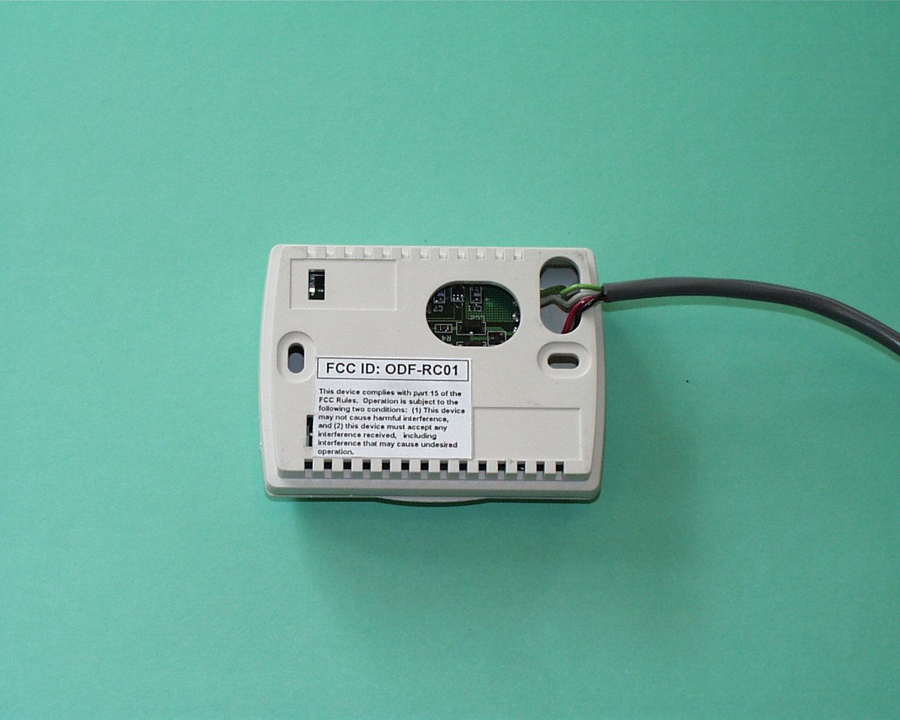
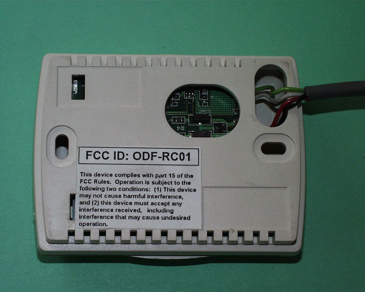
ODF-RC01Remote thermostat receiver
Osirix Incorporated
Click to zoom
Application Details
- Equipment Class
- CYY - Communications Receiver used w/Pt 15 Transmitter
- Date of Grant
- Apr 26, 1999
- Application Purpose
- Original Equipment
- Date of Application
- Mar 27, 1999
- Equipment Note
- Remote thermostat receiver
- Frequency Range
- 417.60000000 - 418.40000000
- Company
- Osirix Incorporated
- Country
- United States
Documents & Files


Document Text
Text extracted from the exhibit documents filed with the FCC. Open a document above to read the original.
Operational Description
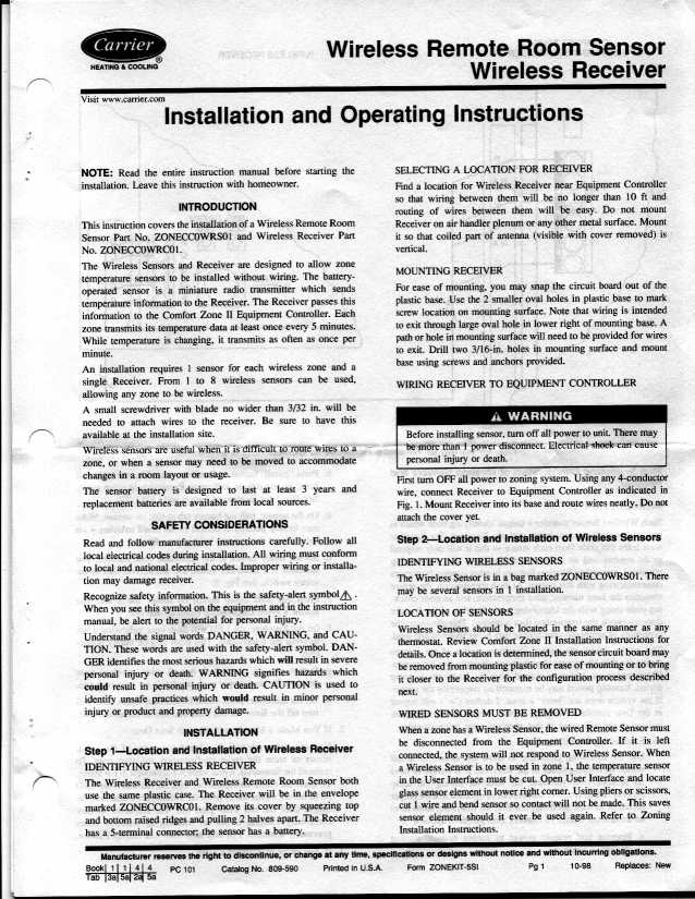
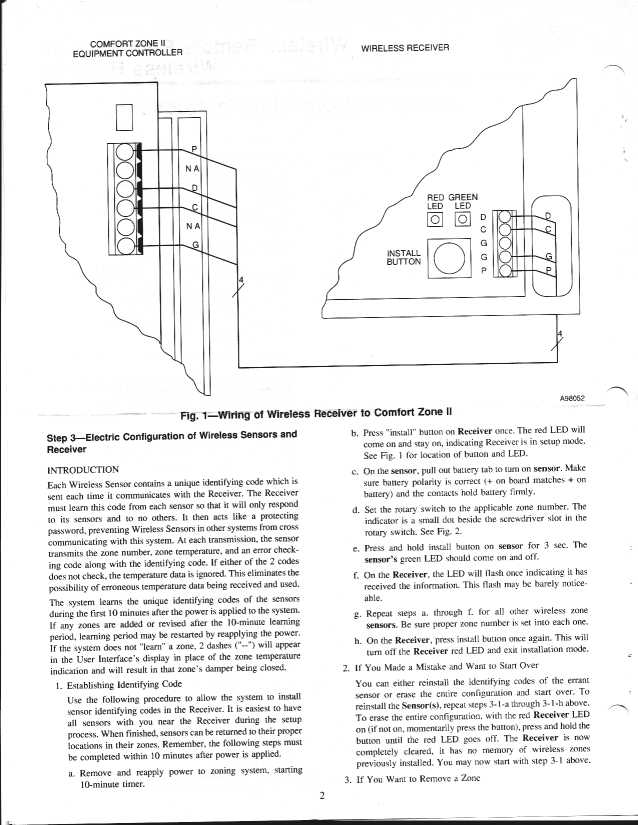
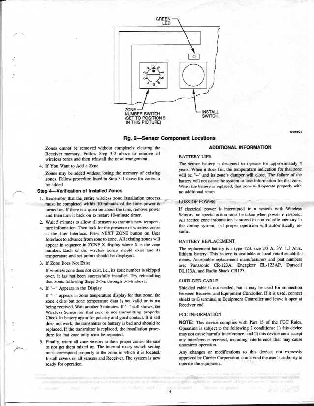
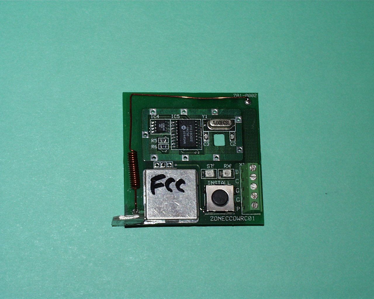
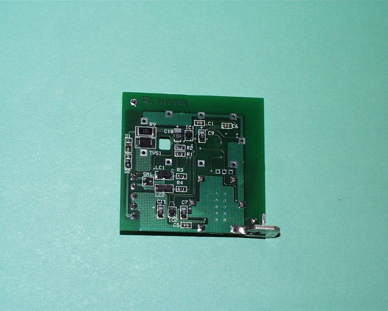
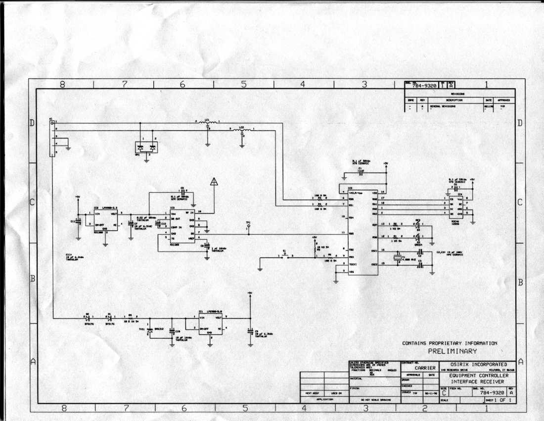
1 Receiver Circuit Description (Summary) Power is supplied to the circuit from an external typical low voltage line from a control thermostat (X1). The 9-12 vdc input is regulated to 5 vdc by (IC1) for use by the circuit. Voltage regulator (IC2) further regulates the 5 vdc to 3.3 vdc for use by the receiver (IC3). The received Manchester encoded data is sent to the microcontroller (IC5) through port pin RB5. The microcontroller checks the address received against the addresses stored in eeprom (IC4), the eeprom is read through port pins RA0-RA3, if the addresses match, the received data is sent to the control thermostat (X1) through port pins RB0 and RB1 and LED (D3) is flashed through current limiting resistor (R1) connected to port pin RB6. Switch (S1) is connected to port pin RB3 (active low). When (S1) is pressed, the microcontroller turns on LED (D4) through port pin RB7. This places the unit into “install mode”. When an installation message is received from a transmitter, the received zone and address information is written to the eeprom (IC4). When switch (S1) is pressed again the unit exits from “install mode”. If the switch is pressed and held for 10 seconds, the eeprom is erased of all data. Receiver Circuit Description: X1 Control thermostat connector - 1. Supplies power to the circuit. 9-12 vdc 2. Connection pin 1 data 3. Connection pin 2 clock 4. Connection pin 3 and 4 gnd D1 and D2 diodes - 1. Redundant reverse polarity protection. IC4 eeprom 1. Stores installed transmitter zone and address information. 2. Connects to the microcontroller IC5using data in, data out, clk, and cs lines. S1 momentary normally open switch - 1. When pressed puts unit into install mode, allowing the received message to be stored in eeprom 2. When pressed again, removes unit from install mode 3. When pressed and held for 10 seconds, erases eeprom data 2 4. Connected to port pin RB3 through resistor R6. RX (D3) LED 1. Flashes when a reception occurs with matching stored eeprom address 2. Connects to port pin RB6 through current limit resistor R1. ST (D4) LED 1. ON when unit is in install mode 2. Connects to port pin RB7 through current limit resistor R2. SM1 1. Transient voltage suppresser LC1, LC2 1. Digital noise filter IC1 1. Voltage regulator 5 vdc IC2 1. Voltage regulator 3.3 vdc IC3 RF Receiver - 1. Converts RF to data
Test Report
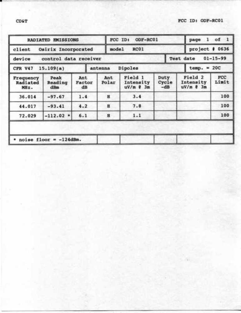
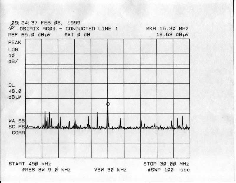
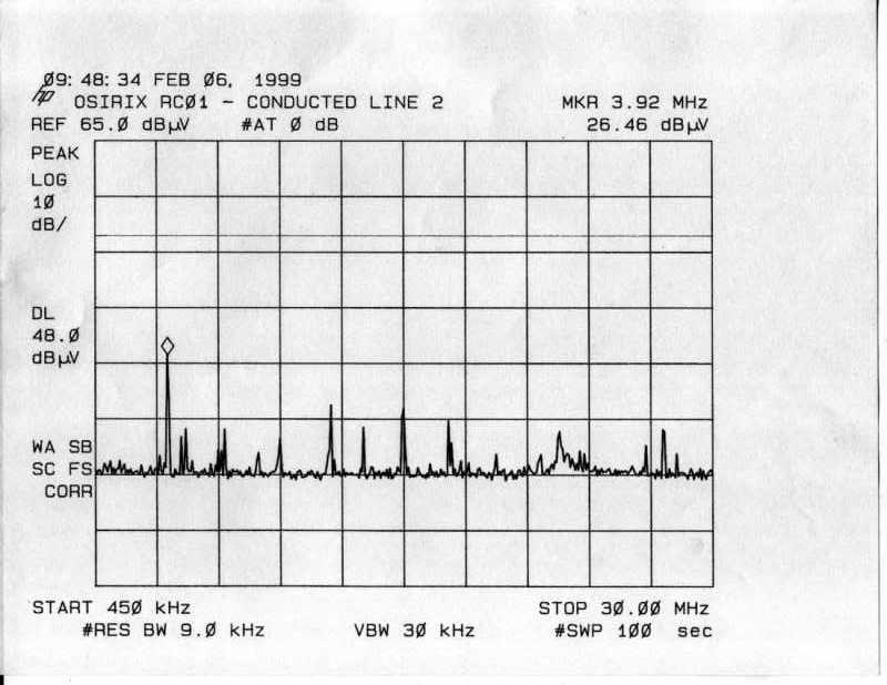
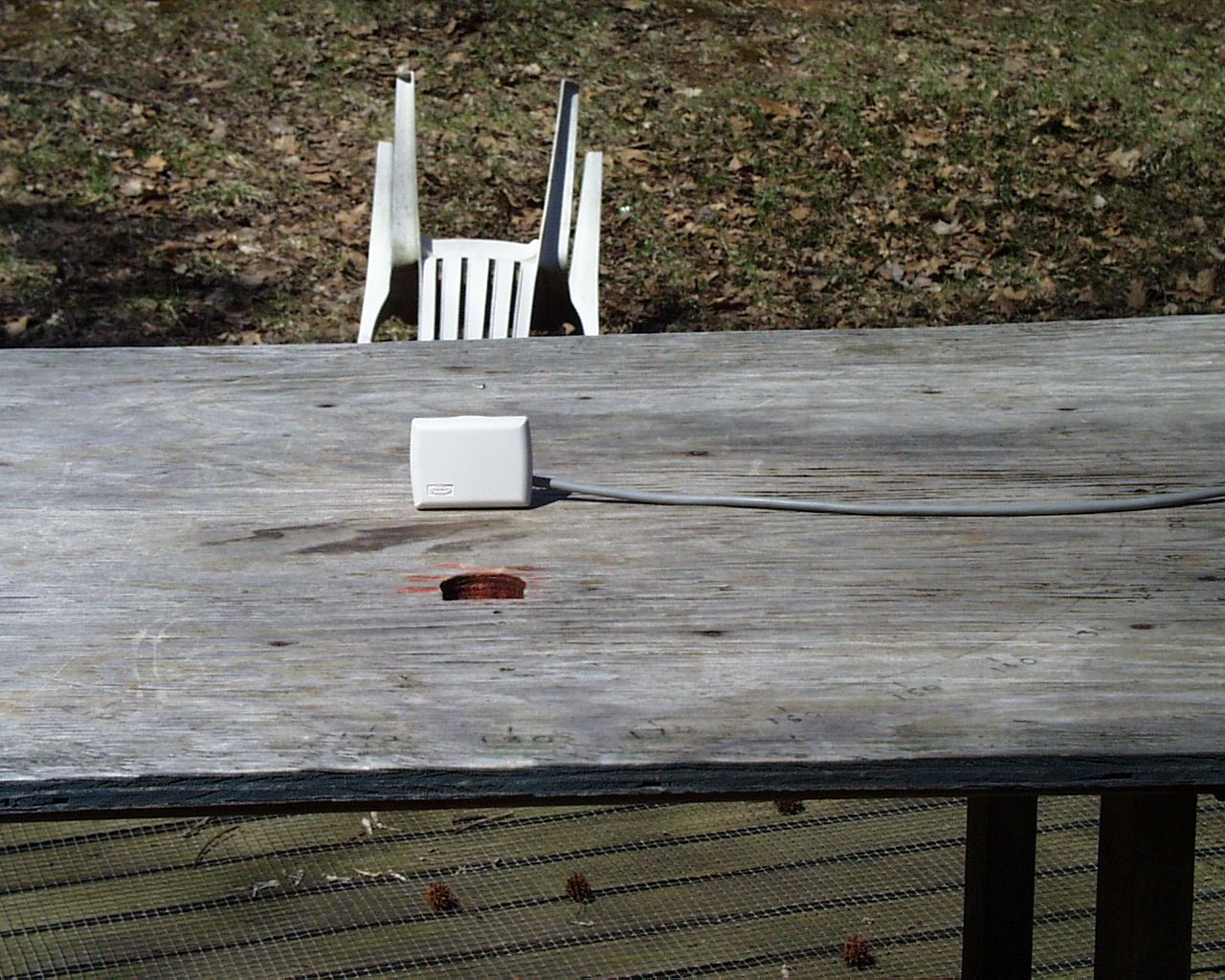
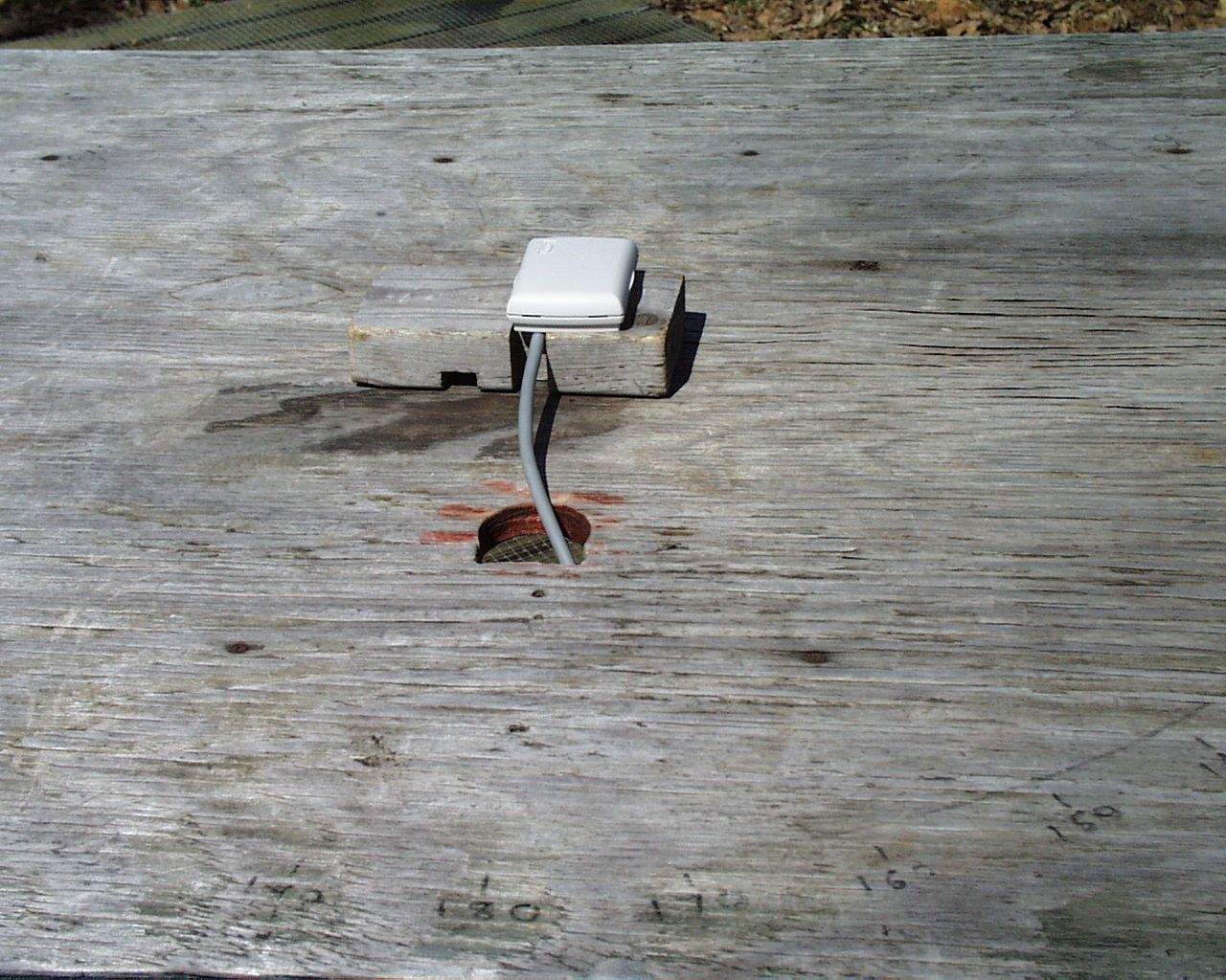
CD&T FCC ID: ODF-RC01 A. DEVICE UNDER TEST The device is a low power data receiver used to receive and decode data transmissions from its companion transmitter (ODF- RS01) and translate the data received in temperature measurements that can then be used to control a heating/cooling system in a manner similar to a standard room thermostat. This product is designed to operate under the provisions of Part 15.109 of the FCC rules, with 15.107 also applicable. The frequency of operation is 418 MHz. nominal. Power for the device was provided by an external NEMA Class II low voltage cable as would be typical for a standard room thermostat. The device is internally regulated at +5 volts and will accept input voltages from +9 to +12 volts DC. This receiver of this device is a TRF circuit using SAW filters to achieve the desired receive frequency. A SAW delay line is used to provide a time lag between two rf amplifiers so that the amplifiers may be alternately turned on and off (approx. 245kHz.) and thus realize a relative high gain without the risk of instability. The entire receiver is contained in a single monolithic integrated circuit. The only external element is the antenna. There are no tunable elements in this device. B. MEASUREMENT PROCEDURE: RADIATED EMISSIONS Field strength measurements were conducted according to the procedures set forth in ANSI C63.4 (1992). Testing was conducted with the device powered from a HP-6216A DC power supply set to 12 volts. The power supply was connected to the mains through slip attached to the base of the turntable. The device under test was placed on a rotating turntable 0.8 meters high, centered at 3 meters distant from the measurement antenna. The device was placed in the center of the turntable and tested in the three logical positions shown in the test setup photographs. This housing is designed to mount on a wall like an ordinary thermostat. However since the possibility exists for mounting on a ceiling, the device was tested in a “flat” and an “upright” position also. In all positions, the primary source of emissions seemed to be in the plane parallel with the plane of the printed circuit board. The field strength measurements were taken using an HP8596E spectrum analyzer, an EMCO 3121C dipole set and an Avantek UJ210 preamp. The device was scanned from 30MHz. to 4.2GHz. and all emissions were noted. In this case the only emissions detected were those that were harmonically related to the clock oscillator fundamental frequency. At each detected frequency of emission, the device was measured by rotating the turntable and adjusting the antenna height over a range of 1 to 4 meters to obtain the maximum output level. This procedure was performed with both horizontal and vertical antenna polarizations with the device in the positions described above. The peak reading for each frequency was recorded in the second column on the data sheet. No emissions were detected above 80 MHz. C. LINE CONDUCTED MEASUREMENTS The line conducted measurements were performed using an OneAC CB-1120 power line conditioner, a Compliance Design LISN, a HP8594E spectrum analyzer and a HP7475A plotter. The resulting plots are provided.
Contact Information
Applicant
Hyo-Jin Jeni Park(President)
(203) 876-9341Fax: (203) 876-9346
Technical Contact
Control Design & TestingThomas W Roche
[email protected](540) 582-2826
6010 Red Fox Drive · Spotsylvania, Virginia · United States
Non-Technical Contact
Control Design & TestingMarguerite A Roche
[email protected](540) 582-2826
Test Firm
Hyak Laboratories, Inc.Rowland Johnson
703-451-1188
Technical Specifications
| # | Rule Parts | Frequency Range | Power Output |
|---|---|---|---|
| 1 | 15B | 417.6 MHz - 418.4 MHz | - |
Other Applications from Osirix Incorporated

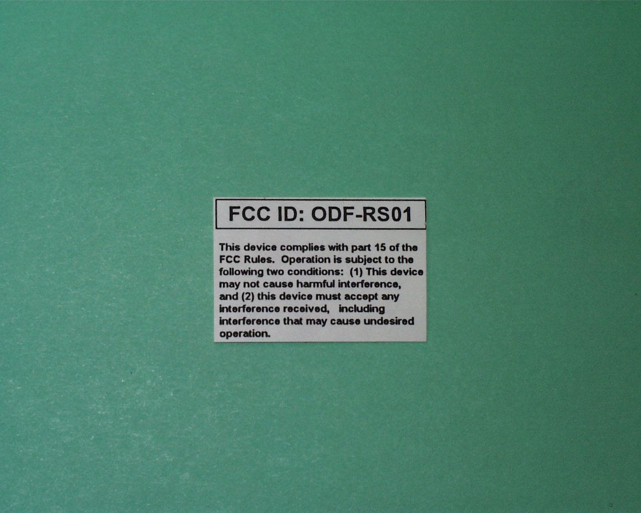
ODF-RS01
Mar 25, 1999Temperature Sensor Transmitter
Equipment Class
DSC - Part 15 Security/Remote Control Transmitter