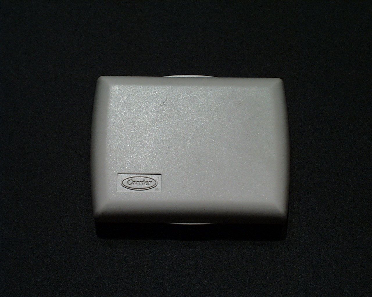
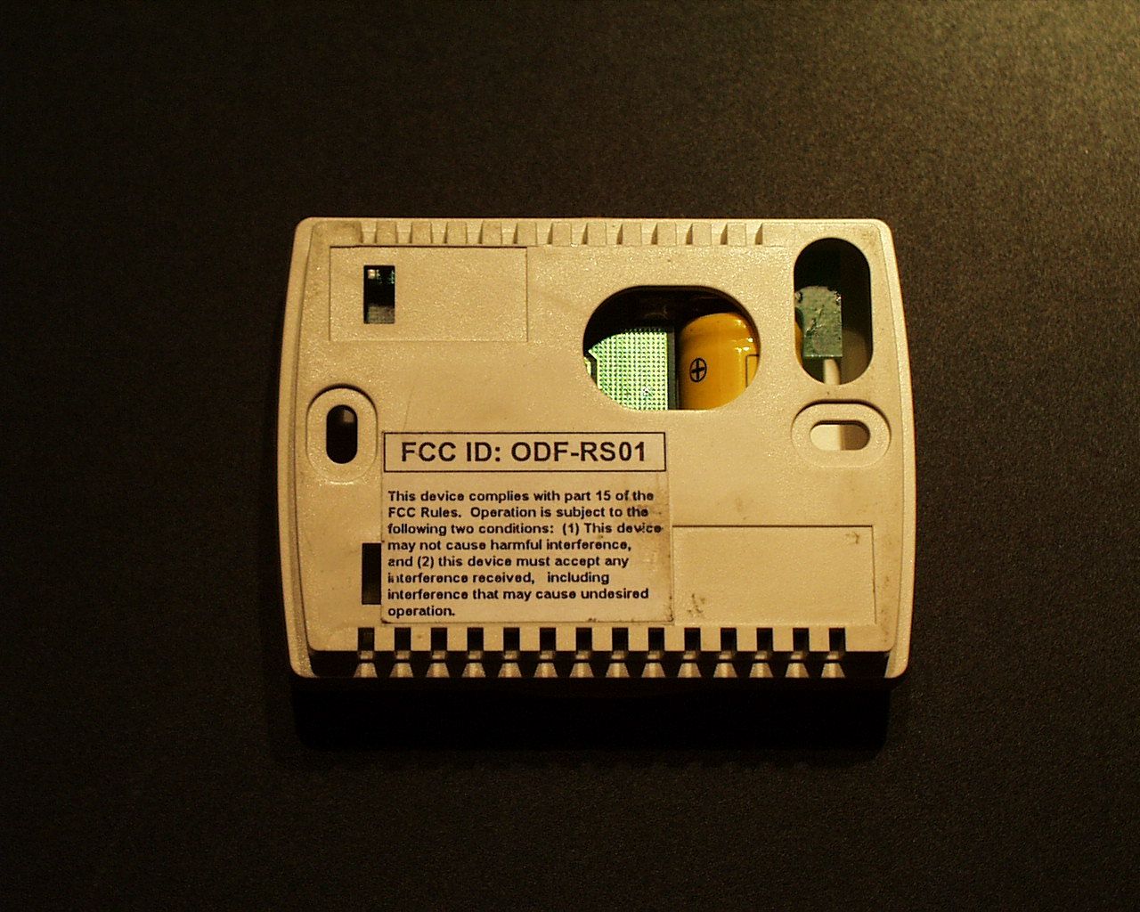
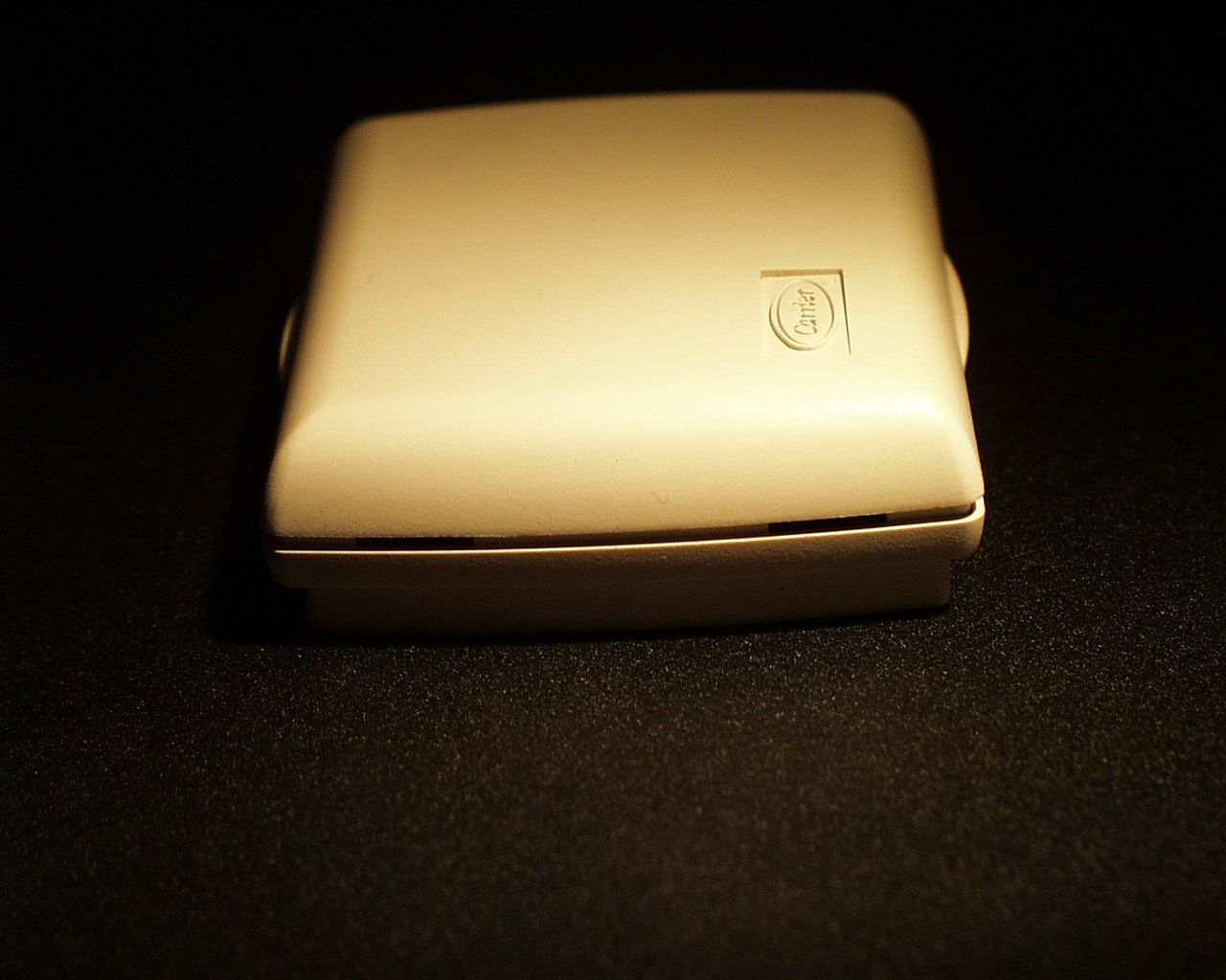
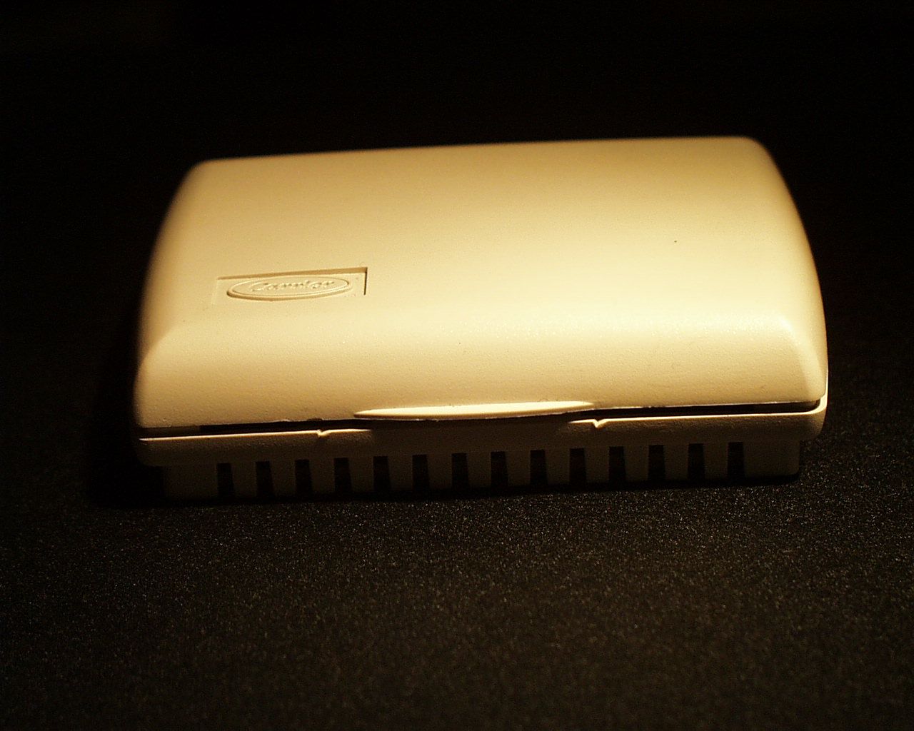
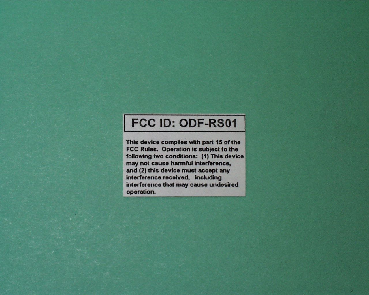
ODF-RS01Temperature Sensor Transmitter
Osirix Incorporated
Click to zoom
Application Details
- Equipment Class
- DSC - Part 15 Security/Remote Control Transmitter
- Date of Grant
- Mar 25, 1999
- Application Purpose
- Original Equipment
- Date of Application
- Jan 22, 1999
- Equipment Note
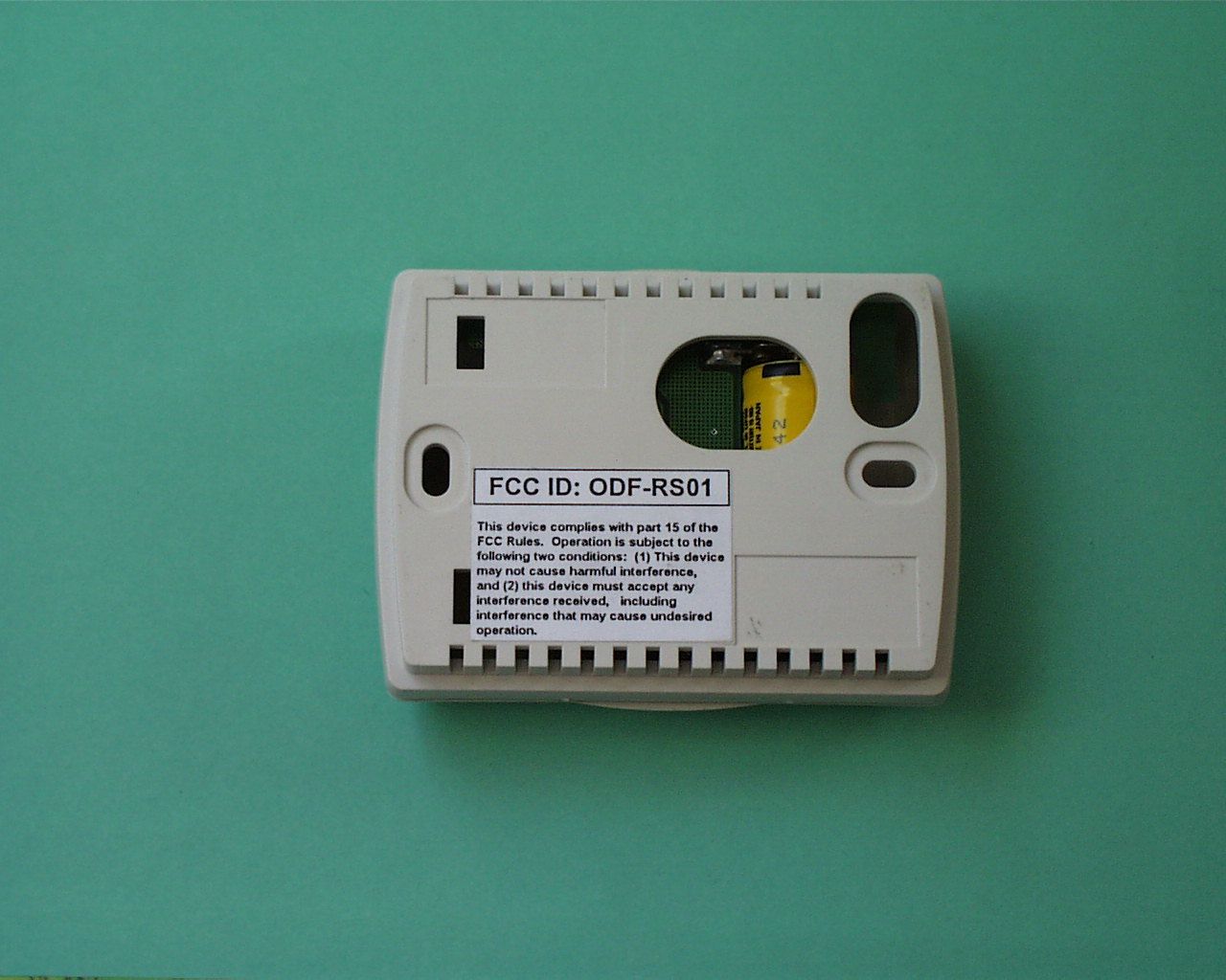
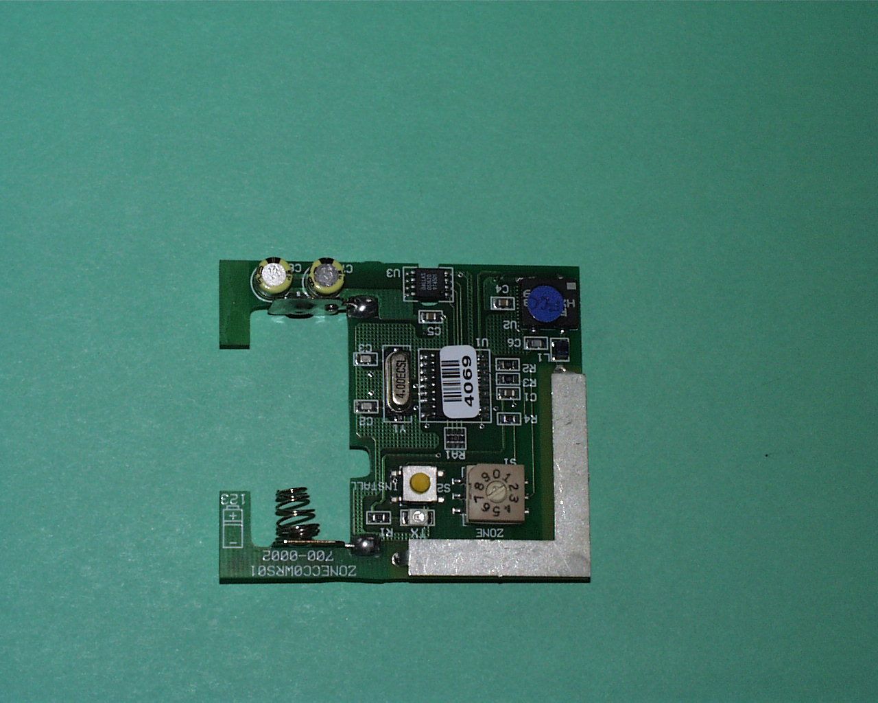
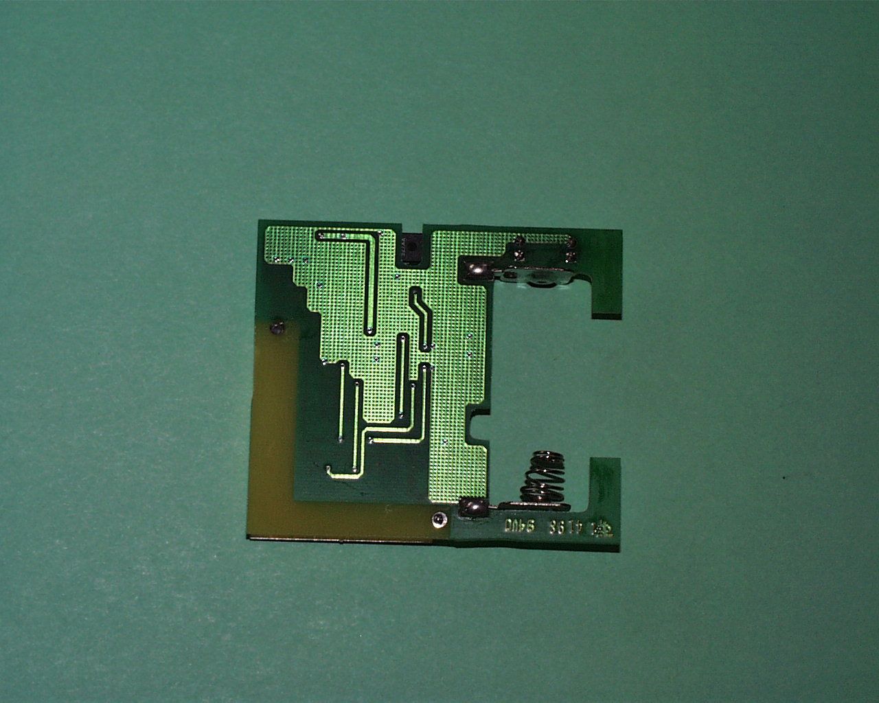
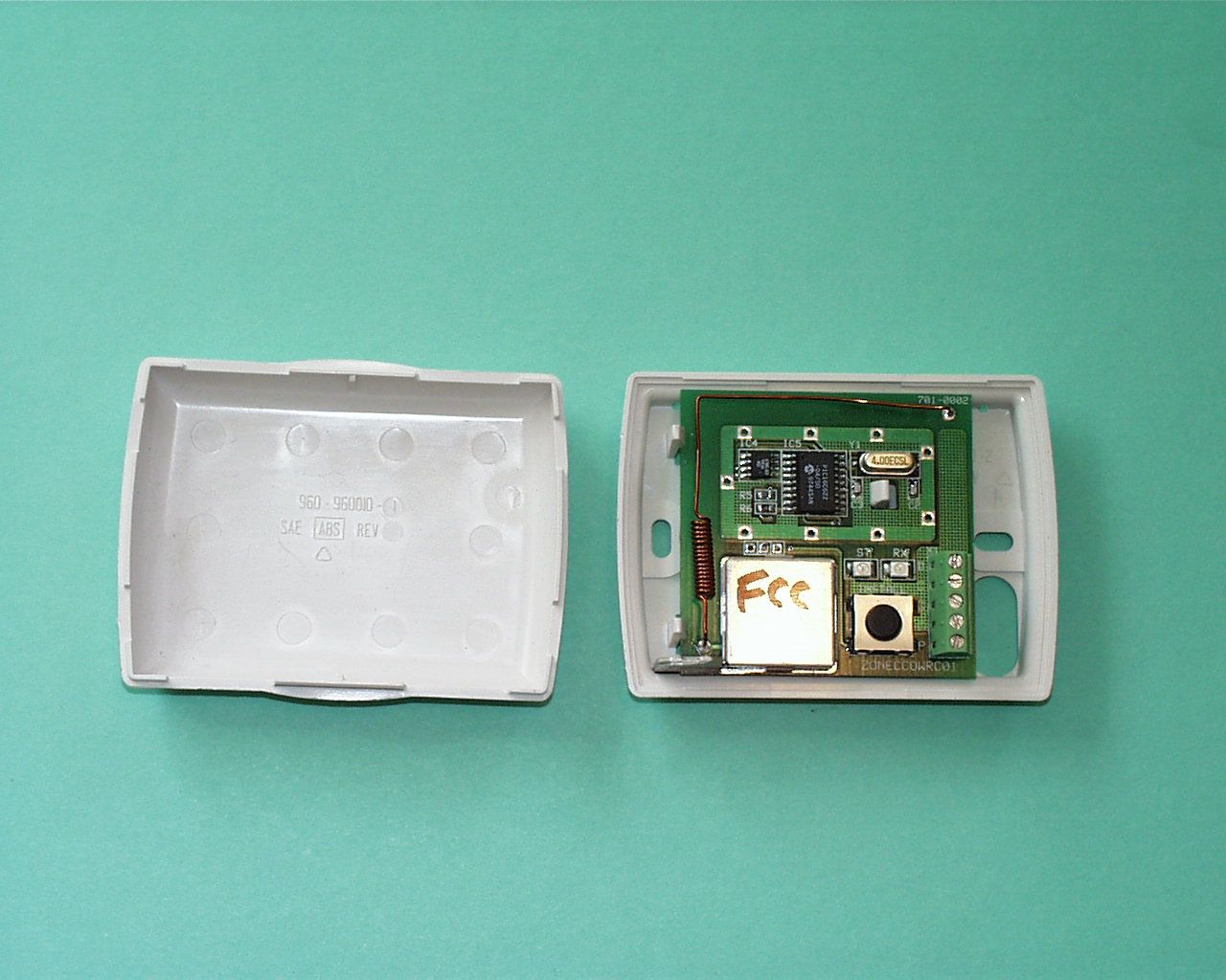
- Temperature Sensor Transmitter
- Frequency Range
- 417.60000000 - 418.40000000
- Company
- Osirix Incorporated
- Country
- United States
Documents & Files
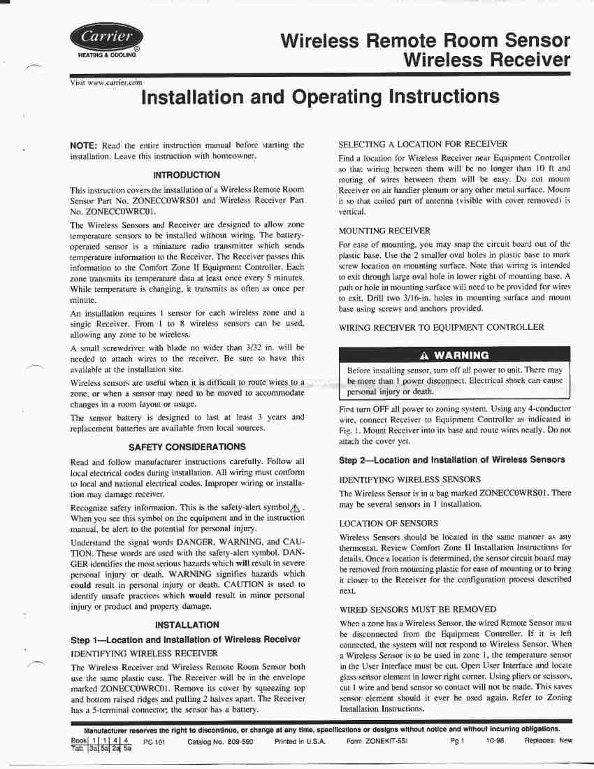
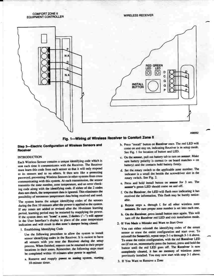
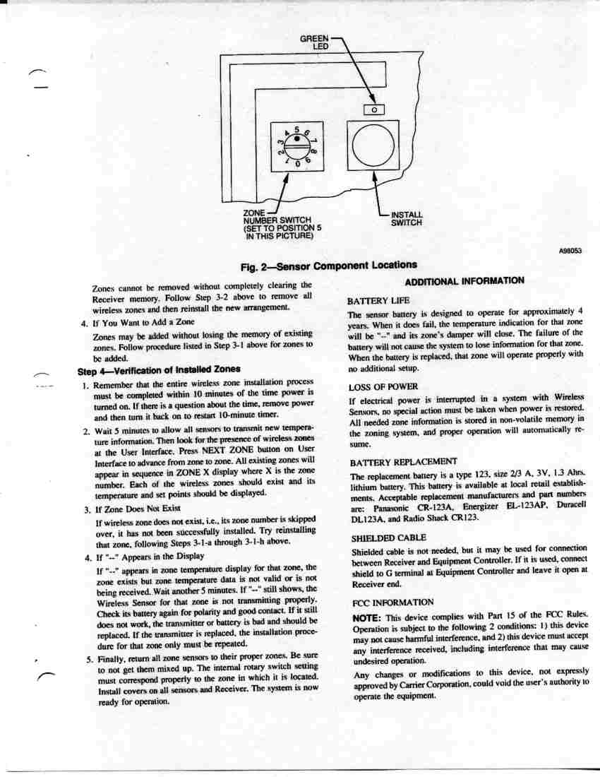
Document Text
Text extracted from the exhibit documents filed with the FCC. Open a document above to read the original.
Test Report
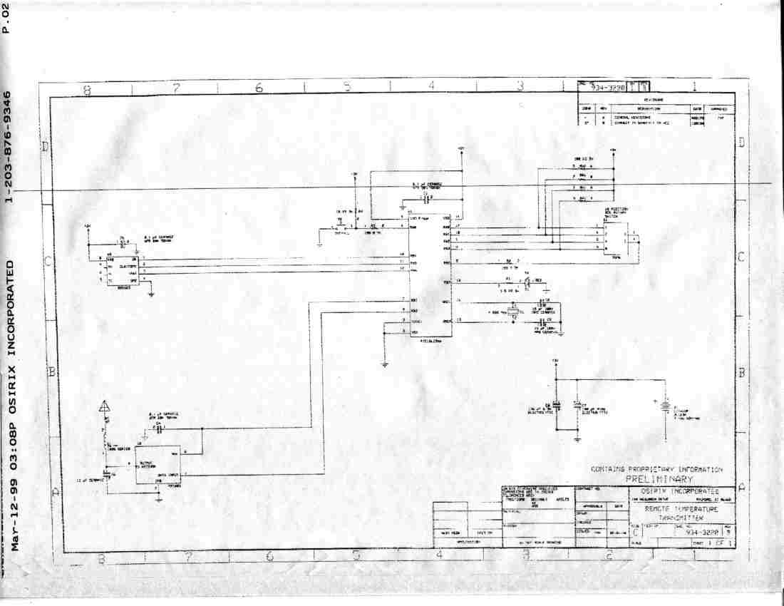
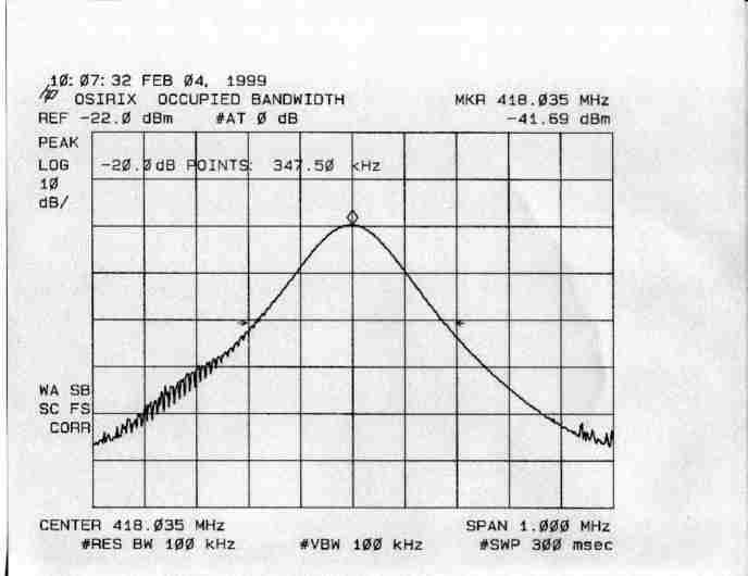
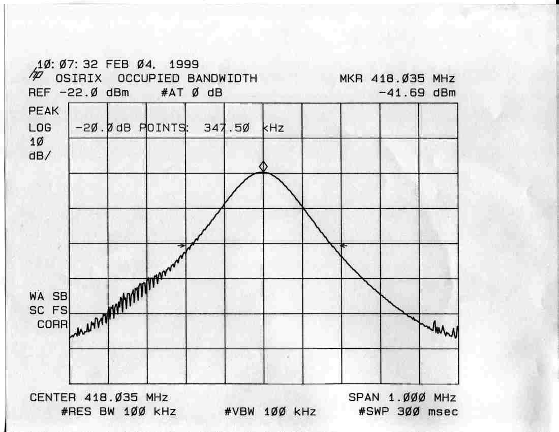
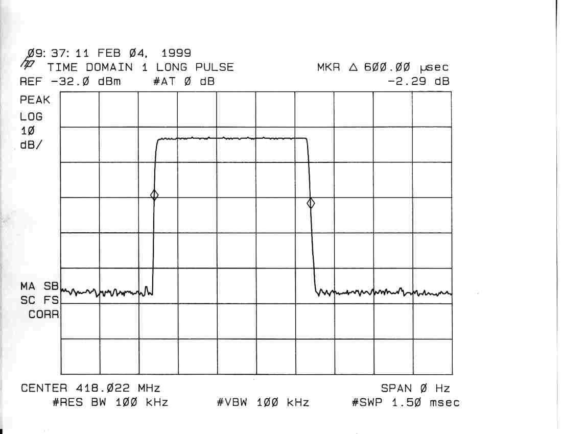
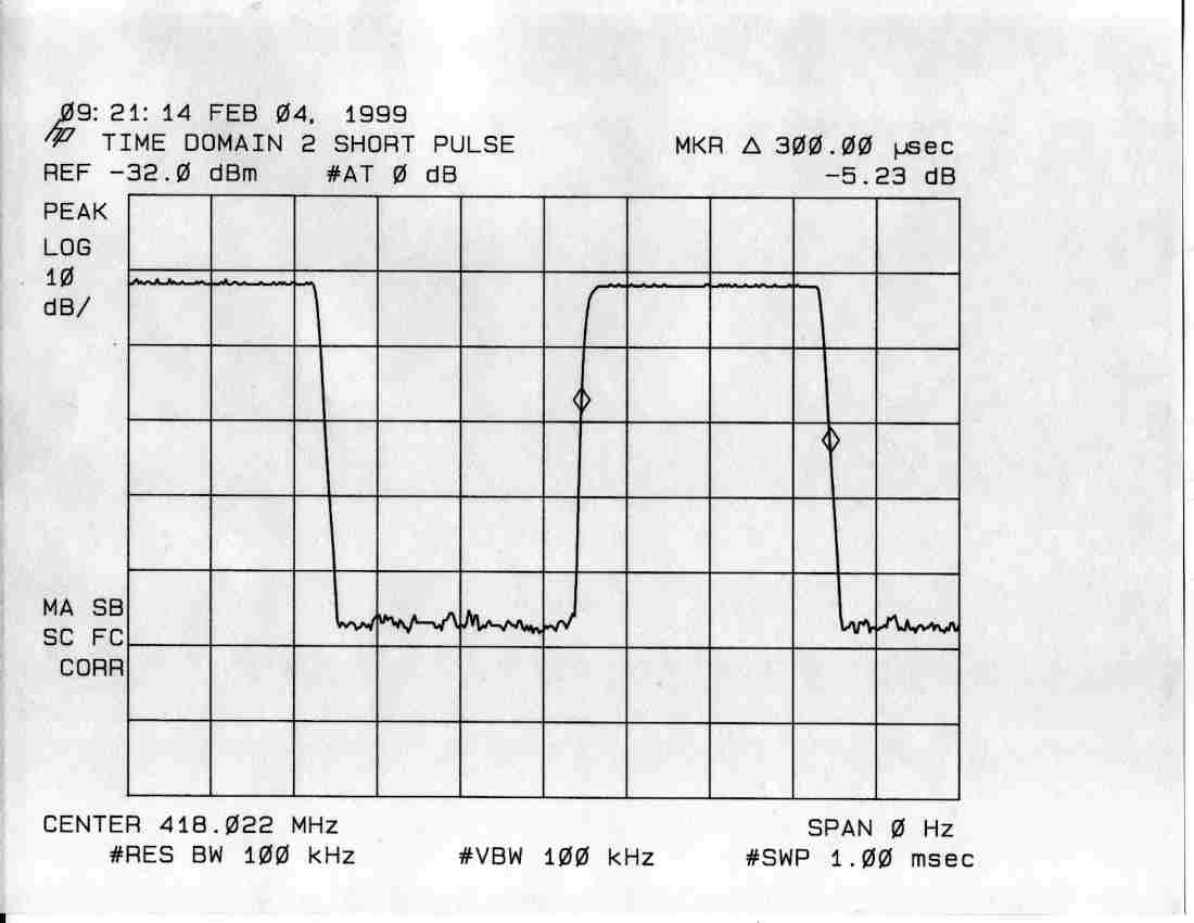
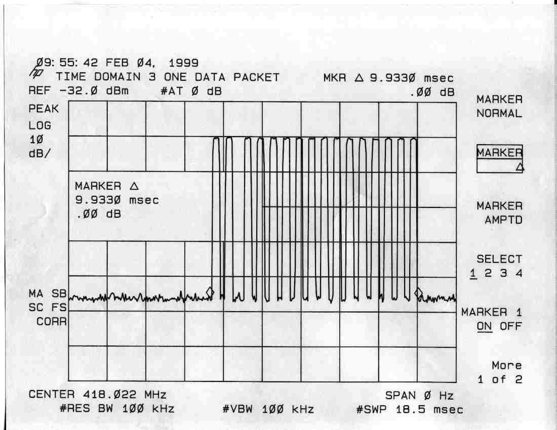
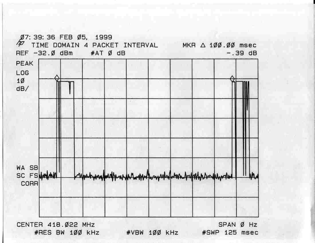
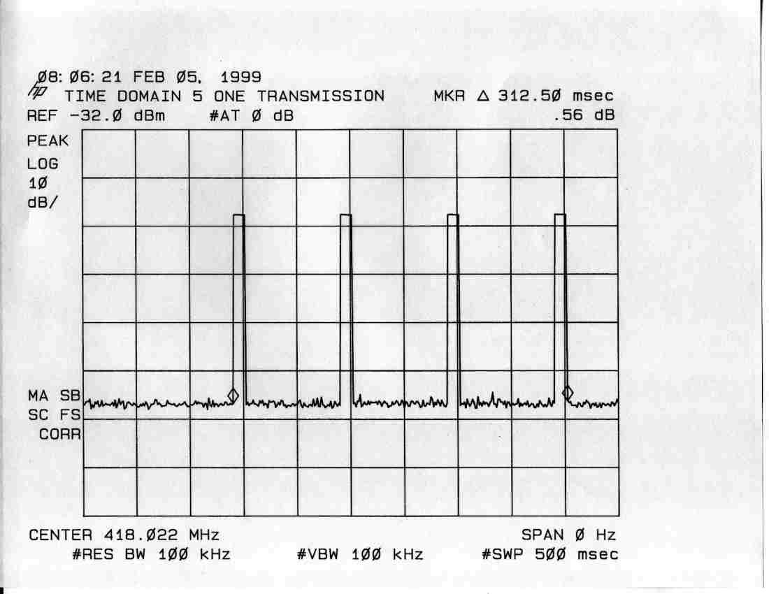
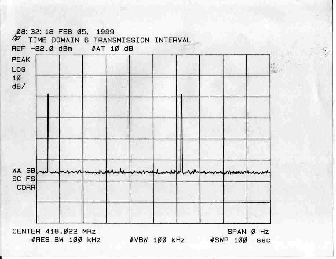
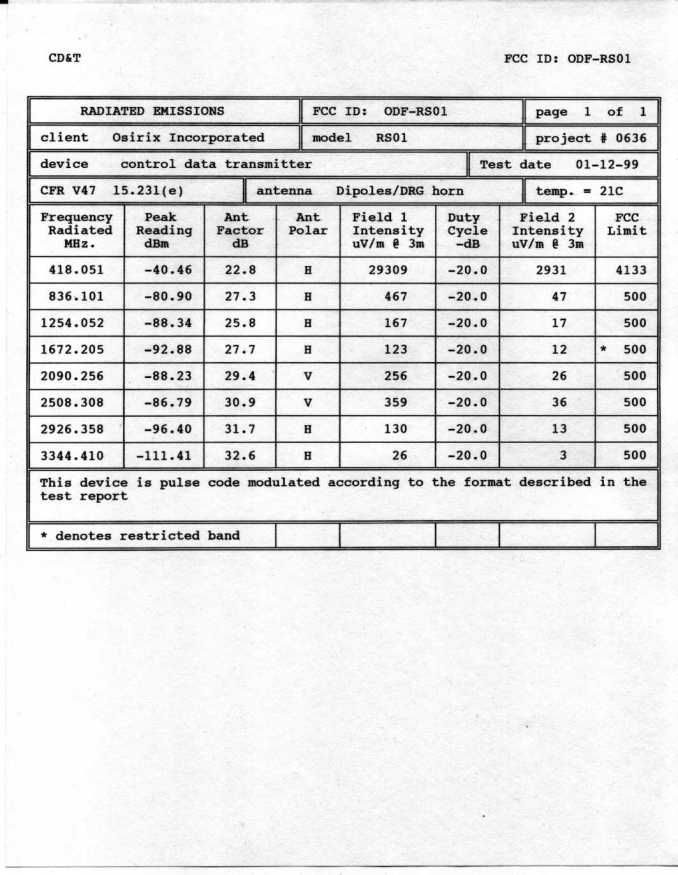
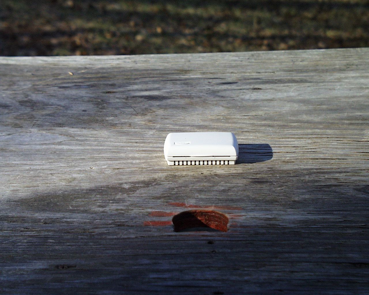
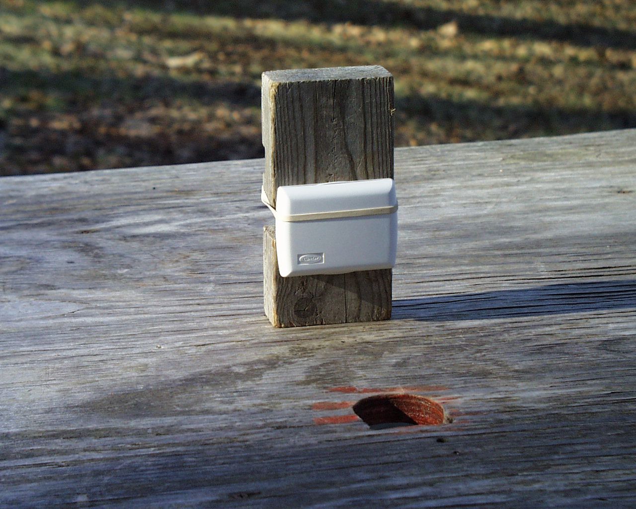
CD&T FCC ID: ODF-RS01 A. DEVICE UNDER TEST The device is a low power data transmitter used to send temperature readings similar to a standard room thermostat but with out the necessity of hard wire connections. This product is designed to operate under the provisions of Part 15.231(e) of the FCC rules. The transmit frequency is 418 MHz. nominal. The modulation mode is on/off keying. Power for the device is provided by an internal 3.0 volt lithium battery. B. MEASUREMENT PROCEDURE: RADIATED EMISSIONS Transmitter field strength measurements were conducted according to the procedures set forth in ANSI C63.4 (1992). Testing was conducted with fresh batteries and monitored periodically to insure that the battery voltage (under load) was maintained at 95% of nominal or better. The device under test was placed on a rotating turntable 0.8 meters high, centered at 3 meters distant from the measurement antenna. The device was placed in the center of the turntable and tested in the two logical positions shown in the test setup photographs. This housing is designed to mount on a wall like an ordinary thermostat. However since the possibility exists for mounting on a ceiling, the device was tested in a “flat” position also. For the purposes of testing, the micro-controller on the test sample was programmed with a special subroutine to transmit the data stream continuously. The field strength measurements were taken using an HP8596E spectrum analyzer, EMCO 3121C dipole set, an EMCO 3115 double ridge guide horn and an Avantek UJ210 preamp. The device was scanned from 30MHz. to 9.2GHz. and all emissions were noted. In this case the only emissions detected were those harmonically related to the fundamental transmit frequency. At each detected frequency of emission, the device was measured by rotating the turntable and adjusting the antenna height over a range of 1 to 4 meters to obtain the maximum output level. This procedure was performed with both horizontal and vertical antenna polarizations with the device in the positions described above. The peak reading for each frequency was recorded in the second column on the data sheet. Scanning for emissions at the 7 th and 8 th harmonics was performed by reducing the distance from the measurement antenna to 1 meter and factoring –9.54dB into the calculation. No emissions were detected above 3.4 GHz. C. DUTY CYCLE CALCULATIONS The transmission format for this device is 50% Manchester phase encoding. Each data packet consists of 16 bits where the first 8 bits represent the address or identity of the device and the last 8 bits contain the temperature data. There is no start bit used in this packet scheme. Time Domain plot #3 shows a single data packet. The data pulses are nominally 300uS. long except where a “0” is followed by “1” which will produce a double width pulse of 600uS. nominal. As shown in Time Domain plots #1 and #2, the pulse duration measurements were taken at points 12dB or more down from peak to insure worst case pulse width. The packets are issued in groups of four, at 100mS. intervals. Referring to Time Domain plots #4 and #5, it is shown that a complete four packet burst occurs within 312.5ms. from start to finish. Time Domain plot #6 shows the periodic transmission interval (approximately 56 seconds) This greater than 30 times the four packet burst sequence (9.375 seconds) and thus satisfies the silent period requirement of Part 15.231(e). The duty cycle is calculated as follows: 16 X 300uS. = 4.8mS. (on time for one packet) 20log(4.8mS./100mS.)= -26.4dB The duty cycle correction factor used for the calculations on the data sheet is –20dB. As provided in Part 15.35.
Contact Information
Applicant
Hyo-Jin Jeni Park(President)
(203) 876-9341Fax: (203) 876-9346
Technical Contact
Control Design & TestingThomas W Roche
[email protected](540) 582-2826
6010 Red Fox Drive · Spotsylvania, VA
Non-Technical Contact
Control Design & TestingMarguerite Roche A Roche
[email protected](540) 582-2826
Test Firm
Hyak Laboratories, Inc.Rowland Johnson
703-451-1188
Technical Specifications
| # | Rule Parts | Frequency Range | Power Output |
|---|---|---|---|
| 1 | 15C | 417.6 MHz - 418.4 MHz | - |
Other Applications from Osirix Incorporated

ODF-RC01
Apr 26, 1999Remote thermostat receiver
Equipment Class
CYY - Communications Receiver used w/Pt 15 Transmitter