OEHDUALTRAKPIDDual Trak Personal Identified Device
Strategic Technologies Inc.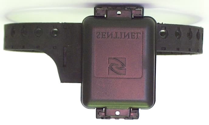
Click to zoom
Application Details
- Equipment Class
- DSR - Part 15 Remote Control/Security Device Transceiver
- Date of Grant
- May 02, 2004
- Application Purpose
- Original Equipment
- Date of Application
- May 02, 2004
- Equipment Note
- Dual Trak Personal Identified Device
- Frequency Range
- 433.28000000 - 434.56000000
- Company
- Strategic Technologies Inc.
- Country
- Canada
Documents & Files
Document Text
Text extracted from the exhibit documents filed with the FCC. Open a document above to read the original.
Users Manual
STRATEGIC Technologies Inc. ACU Overview iTRX Series Users Guide (STI) Feb 6, 2004 PAGE 1 NOTICE : This Users Guide is for use with version 3.2 of the iTRX series ACU Firmware See Page 7, ACU Operations (Active Mode) for information regarding how to determine the ACU Firmware version. Different versions of the ACU software may not have the same features described in this manual and / or may function differently than this manual states. United States FCC, Part 15 These devices comply with Part 15 of the FCC rules. Operation is subject to conditions: (1) This device may not cause harmful interference, and (2) this device must accept interference received, including interference that may cause undesired operation. ITX FCC Identifier: OEHDUALTRAKPID LOCK FCC Identifier: OEHSTILOCK NOTE: THE MANUFACTURER IS NOT RESPONSIBLE FOR ANY RADIO OR TV INTERFERENCE CAUSED BY UNAUTHORIZED MODIFICATIONS TO THIS EQUIPMENT. SUCH MODIFICATIONS COULD VOID THE USER’S AUTHORITY TO OPERATE THE EQUIPMENT. Industry Canada These devices comply with requirements of the radio standards specifications and procedures issued by Industry Canada. LOCK: Certificate No. 9937, certification no. 32851021360. This manual is for users of Strategic’s equipment only. All matters concerning this manual should be directed to Strategic Technologies Inc. Printed in Canada. All rights reserved. Strategic Technical Support For help related to the equipment in this Users’ Guide, call (604) 576-8658, ext. 230. STRATEGIC Technologies Inc 2 iTRX Series Users Guide (STI) Feb 6, 2004 STRATEGIC Technologies Inc ACU Overview iTRX Series Users Guide (STI) Feb 6, 2004 3 Table Of Contents ACU Overview .......................................................................................................................................... 5 Required field equipment for installing and/or removing a unit ..................................................... 5 ACU Basics............................................................................................................................................... 6 Turning the ACU on ...................................................................................................................... 6 Turning the ACU off ...................................................................................................................... 6 ACU Indicator Lights and Buttons ................................................................................................. 7 ACU Operation (Active Mode)....................................................................................................... 7 ACU Calling the Central Computer ...............................................................................................8 Call Attempt Error Messages ............................................................................................ 8 Blind Dial Mode ................................................................................................................. 9 iTX Basics ............................................................................................................................................... 10 Features ...................................................................................................................................... 10 Resetting the iTX......................................................................................................................... 10 LOCK Basics .......................................................................................................................................... 11 Replacing the Battery.................................................................................................................. 11 CMU Basics ............................................................................................................................................ 12 Installation ................................................................................................................................... 12 Removal ...................................................................................................................................... 12 ACU Installation Procedures................................................................................................................... 13 Active Mode Installation ......................................................................................................................... 14 Pre-Installation ............................................................................................................................ 14 ACU Installation - Quick Install.................................................................................................... 14 iTX Installation................................................................................................................. 15 Figure 5: Attaching the strap to the baseplate..................................................... 15 Figure 6: Sliding the iTX onto the baseplate........................................................ 16 ACU Installation - using Test Mode............................................................................................. 17 Installation Completion .................................................................................................... 17 De-Installation / Removal ............................................................................................................ 18 Figure 7: How to cut the iTX for removal ............................................................. 19 Passive Mode ......................................................................................................................................... 20 Important Information Regarding Passive Mode Operation ........................................................ 20 Passive Mode Installation ............................................................................…
Text truncated - open the document above for the full version.
Block Diagram
Commercial in Confidence 01080301-0053 Iss 1.0 Ionocom Communications Inc., North Vancouver BC Canada. Page 1 Introduction This document is a circuit description for the PID 2002 printed circuit assembly, Ionocom part number 01080301-0023 Issue 2. It should be read in conjunction with the following documents: Ionocom Doc number Strategic Doc number Description 01080301-0006-1.0 Specification, PID 2001 Printed Circuit Assembly 01080301-0015-3 Schematic, Printed Circuit Assembly, PID 2002 Circuit Description Overview The functional block diagram for the PID 2002 printed circuit assembly is shown below. The printed circuit assembly interfaces with a battery and a conductive strap. Components exist to support a tamper-detect switch, but this functionality is not implemented in this issue of the PID. Strap Battery Strap Cut Detect Tamper Detect Power Supply Control PLL and Amplifier 800kHz Receiver PID Printed Circuit Assembly Antenna Sleep Timing Filter Lock Detection Power Supply The battery is connected to the circuit via contacts J1 and J2. Because the battery has a fairly high internal resistance, particularly when it is nearing the end-of-life, capacitors C12, C13 and C18 are provided as reservoirs. They are capable of directly supplying the current pulse needed for a transmission, leaving the battery to re-charge them during the sleep period. Battery voltage varies from 3.3V with a fresh battery to 2.5V near end-of-life. During a transmission the voltage across the reservoir capacitors can fall to around 2.2V. Switched mode regulator U6 converts this to a regulated 3.6V VPWR rail during a transmission. During the sleep period the regulator is disabled and battery voltage passes straight through L11 and D1 to provide power to those parts of the circuit that remain active. Along with regulator U6, inductor L11, diode D1 and reservoir capacitor C16 form the switched mode regulator. Potential divider R32, R33 and R35 set the output voltage at nominally 3.6V. By grounding
Cover Letter(s)
March 30, 2004 TO: Whom It May Concern RE: Strategic Transmitter Dualtrak PID Submission (OEHDUALTRAKPID) The Schematic Diagrams, Theory of Operations and Bill of Materials in our submission contain information proprietary to Strategic Technologies Inc. and form a basis for our intellectual property with respect to our product design. As such, we have requested that this information not be available for general public access and is to remain confidential Yours truly, Strategic Technologies Inc. Steve Rosset Vice-President, Technical Operations
External Photos
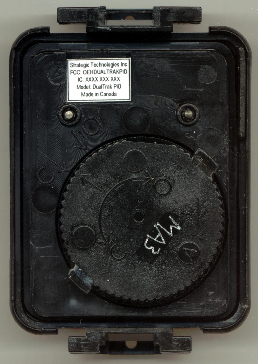
Strategic Technologies Inc. DualTrak PID – Product Photos Figure 1: External Front view assembled with strap Figure 2: External Front view Figure 3: External Rear view Figure 4: External Top view with assembled strap
Internal Photos
Strategic Technologies Inc. DualTrak PID – Product Photos Figure 1: Internal Side view showing assembled unit Figure 2: Internal PCB Top view Figure 3: Internal PCB Rear view
Test Report
EMC Compliance Report Rev 1.1 Strategic Technologies Inc. – DualTrak PID Page 1 of 20 Strategic Technologies, Inc. DualTrak PID Compliance Test Report and Report of Measurements per FCC CFR47 Part 15.203; 15.205; 15.207; 15.231 Revision 1.1 April 29, 2004 Approved by Checked by Robert Stirling, P.Eng.Date Protocol Labs, Abbotsford B.C., Canada FCC Registration Number 96437 Industry Canada Registration Number IC3384 EMC Compliance Report Rev 1.1 Strategic Technologies Inc. – DualTrak PID Page 2 of 20 Index FCC CFR47 Part 15/C Report of Measurements .......................................................................................... 4 FCC CFR47 Part 15 Subpart C Report of Measurements ............................................................................ 6 1. Antenna Requirement ................................................................................................... 6 1.1 Regulation...................................................................................................................... 6 1.2 Result ............................................................................................................................ 6 2. Conducted Emissions Tests ........................................................................................ 6 2.1 Result ............................................................................................................................ 6 3. Periodic Operation Exceeding 15.231(a) ..................................................................... 7 3.1 Regulation...................................................................................................................... 7 3.2 Test Procedures ............................................................................................................8 3.3 Calculation of Field Strength Limits ............................................................................... 8 3.4 Calculation of Average Correction Factor...................................................................... 8 3.5 Result ............................................................................................................................ 9 433.201MHz, Channel A; Low Peak.................................................................................. 10 433.350MHz, Channel A; High Peak ................................................................................. 11 434.473MHz, Channel B; Low Peak.................................................................................. 12 434.635MHz, Channel B; High Peak ................................................................................. 13 4. Duration of Transmission and Minimum Silent Period ........................................... 14 4.1 Regulation.................................................................................................................... 14 4.2 Result .......................................................................................................................... 14 Plot showing the Pulse Duration:....................................................................................... 14 Plot showing the Pulse Period and Silent Period:.............................................................. 15 5. 20dB Bandwidth ......................................................................................................... 16 5.1 Regulation.................................................................................................................... 16 5.2 Calculation of 20dB Bandwidth and Result.................................................................. 16 6. Frequency Tolerance in the 40.66MHz to 40.76MHz Band ...................................... 16 6.1 Regulation.................................................................................................................... 16 6.2 Result .......................................................................................................................... 16 7. Restricted Bands Review ........................................................................................... 17 7.1 Regulation.................................................................................................................... 17 EMC Compliance Report Rev 1.1 Strategic Technologies Inc. – DualTrak PID Page 3 of 20 7.2 Result .......................................................................................................................... 17 Test Setup Photos: ............................................................................................................ 18 EMC Compliance Report Rev 1.1 Strategic Technologies Inc. – DualTrak PID Page 4 of 20 FCC CFR47 Part 15/C Report of Measurements Testing Details TESTED BY: Rob Stirling / David Johanson TEST CONDITIONS:Temperature and Humidity: 7.9 ° C 55% TEST VOLTAGE:120 Vac 60 Hz Test Facilities Protocol Labs 28945 McTavish Rd. Abbotsford BC, Canada, V4X 2E7 FCC Registration Number 96437 Industry Canada Registration Number IC3384 Test Equipment List: EMISSIONS: DeviceModel NumberSerial No.Last Cal.Next Cal AntennaEMCO 3141 Bilog112710/27/0310/27/04 Spectrum Analyzer Hewlett Packard 8566B 2241A02102 11/14/0311/14/04 RF- Preselector Hewlett Packard 85685A 3107A01222 04/10/0304/10/04 Quasi-Peak Adapter Hewlett Packard 85650A 2043A00240 04/13/0304/13/04 TowerRhientech LabsCustomN/AN/A TurntableProtocolCustomN/AN/A EMC Compliance Report Rev 1.1 Strategic Technologies Inc. – DualTrak PID Page 5 of 20 Company Under Test COMPANY:Strategic Technologies Inc. ADDRESS:A102 – 17802 66 th Avenue Surrey, BC V3S 7X1 CONTACT PERSON:Mr. Steve Rosset PHONE NUMBER:604-576-8658 Equipment Under Test THE TEST SYSTEM: EUT:DualTrak Personal Identifier Device. Manufacturer: Strategic Technologies Inc. Part Numbers:DualTrak PID Tag Serial Number:19282 Auxiliary Equipment:3VDC Regulated Power Supply. (Note: this equipment normally uses a 3VDC Lithium Coincell. The Auxiliary power supply was requi…
Text truncated - open the document above for the full version.
Test Setup Photos
EMC Compliance Report Rev 1.0 Strategic Technologies Inc. – DualTrak PID Page 15 of 17 Test Setup Photos: Emission Set Up Front View EMC Compliance Report Rev 1.0 Strategic Technologies Inc. – DualTrak PID Page 16 of 17 Emission Set Up Back View EMC Compliance Report Rev 1.0 Strategic Technologies Inc. – DualTrak PID Page 17 of 17 Emission Set Up Table Top
Contact Information
Applicant
Steve Rosset(Vice President, Technical Operations)
Test Firm
Protocol LabsRobert Stirling
Technical Specifications
| # | Rule Parts | Frequency Range | Power Output |
|---|---|---|---|
| 1 | 15.231(e) | 433.28 MHz - 434.56 MHz | - |
Other Applications from Strategic Technologies Inc.
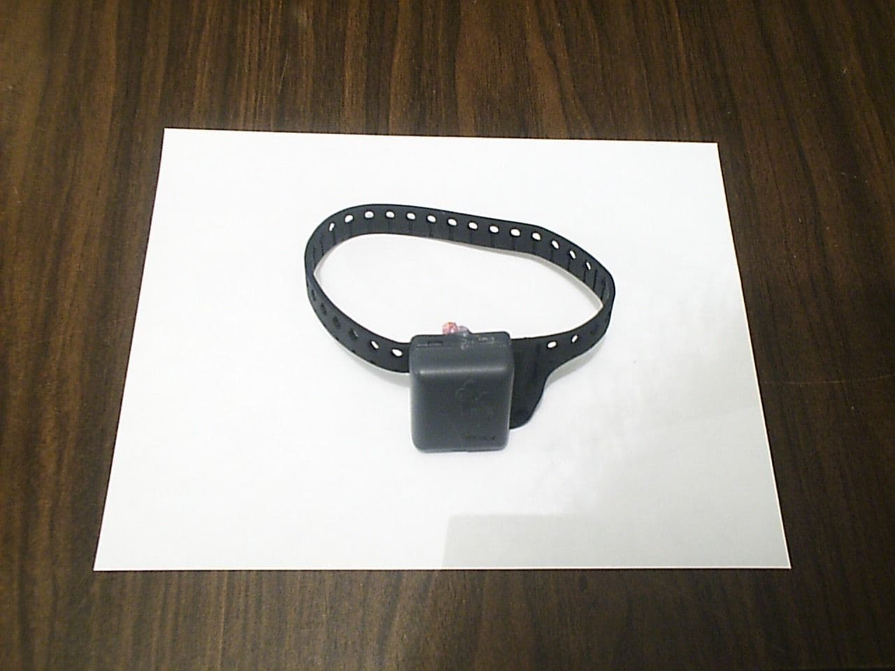
OEHSTISURETRAC
Mar 28, 1999DSC - Part 15 Security/Remote Control Transmitter
Equipment Class
DSC - Part 15 Security/Remote Control Transmitter