OEHSTISURETRAC
Strategic Technologies Inc.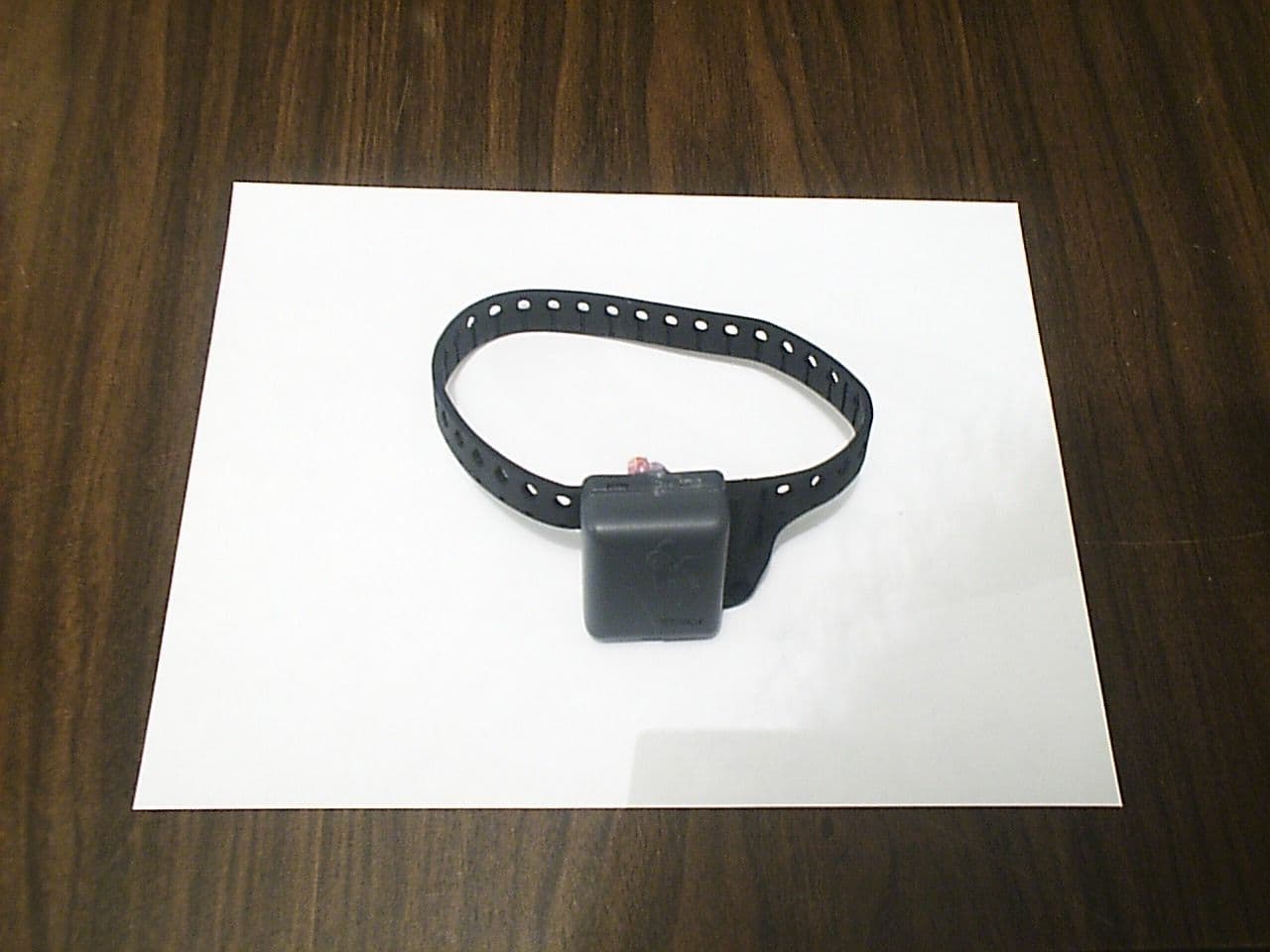
Click to zoom
Application Details
- Equipment Class
- DSC - Part 15 Security/Remote Control Transmitter
- Date of Grant
- Mar 28, 1999
- Application Purpose
- Original Equipment
- Date of Application
- Feb 01, 1999
- Frequency Range
- 433.28000000 - 434.56000000
- Company
- Strategic Technologies Inc.
- Country
- Canada
Documents & Files
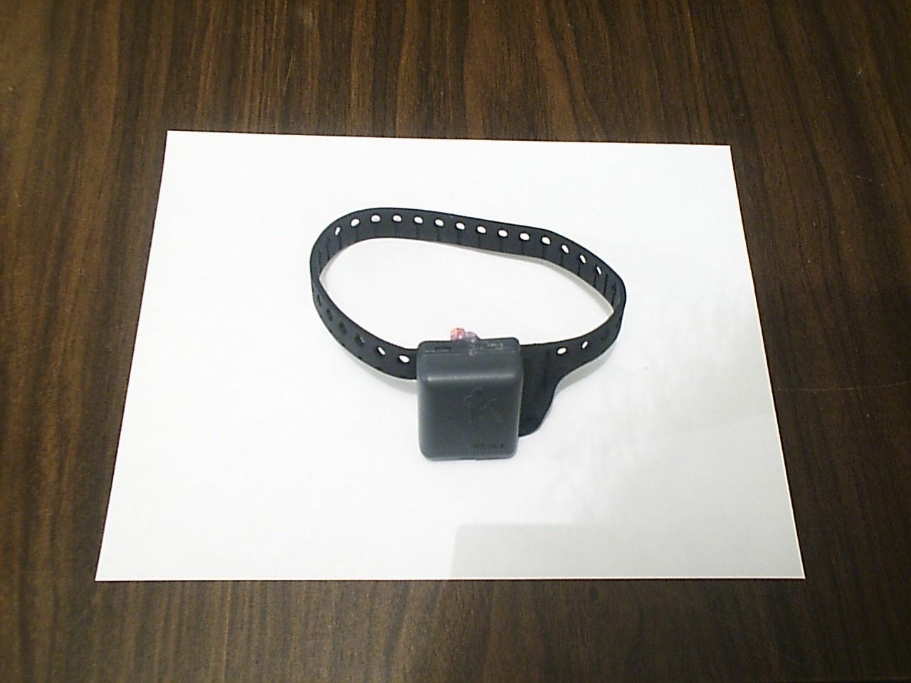
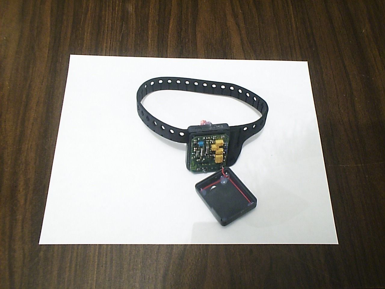
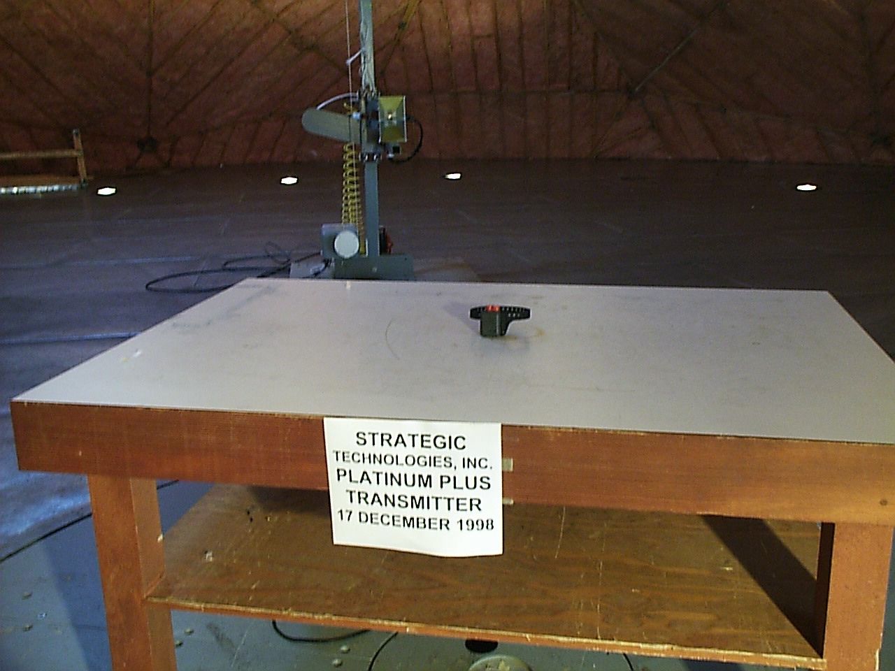
Document Text
Text extracted from the exhibit documents filed with the FCC. Open a document above to read the original.
Users Manual
STRATEGIC Technologies Inc. Ref. Doc. No. R.D.5.3.1I Rev 0.1 Jan 18/1999Page 1 SPECIAL NOTE : This Users Guide is for use with v2.1 of the PRU+ Firmware. See PRU+ Basics on Page 9 for information regarding how to determine the PRU+ Firmware version. Different versions of the PRU+ software may not have the same features described in this manual and / or may function differently than this manual states. FCC STATEMENT: This device complies with Part 15 of the FCC rules. Operation is subject to conditions: (1) This device may not cause harmful interference, and (2) this device must accept interference received, including interference that may cause undesired operation. Changes or modifications not expressly approved by STRATEGIC Technologies Inc. invalidate any approval or warranty applying to the product and can void the user’s authority to operate this equipment. STRATEGIC Technologies Inc. Ref. Doc. No. R.D.5.3.1I Rev 0.1 Jan 18/1999Page 2 Platinum Plus New Features and Enhancements Quick Install Mode This new feature makes installation of the PRU+ quicker and more convenient. The visual display screen on the front of the PRU+ will prompt the installer for each step and guide them through the installation process. For a more detailed description, see page 44. Domestic Violence Deterrent System - more detailed support The PRU+ now has more detailed support for Strategic’s Domestic Violence Deterrent system. The Domestic Violence Deterrent System is designed to provide curfew monitoring for both the offender and the victim. The PRU+ contains a specific setting for the transmitter, in the form of a pendant, which is worn by the victim. This enables the PRU+ to determine if the offender, wearing a transmitter, entered the victim’s area or if the pendant transmitter was activated by the victim. There is also support for an optional panic button that enables the victim to send a panic message to the monitoring center. For a more detailed description, see page 32. Tone Dialling The PRU+ now supports both styles of dialling (tone and pulse). For further details see page 36. A more convenient method to set a Dial Prefix In some situations (ie: hotels and offices)., a dial prefix may be required to enable the PRU+ to dial from that location. An extra digit, such as “9", can be added without necessitating a change of the entire number to be dialled. For a more detailed description, see page 38. Motion Sensor The PRU+ now has the ability to determine if it is being moved. See page ? For more details. Automatic saving of changes All changes to any programmed settings are now automatically saved when they are edited. STRATEGIC Technologies Inc. Ref. Doc. No. R.D.5.3.1I Rev 0.1 Jan 18/1999Page 3 Table Of Contents PRU+ Overview ............................................................................................................................Page 6 Required field equipment for installing and/or removing a unit .......................................Page 6 PRU+ Basics ................................................................................................................................Page 7 Turning the PRU+ on .......................................................................................................Page 7 Turning the PRU+ off .......................................................................................................Page 7 Figure 2 : Front Panel Display......................................................Page 7 PRU+ Indicator Lights and Buttons..................................................................................Page 8 PRU+ Operation (Run Mode)...........................................................................................Page 8 PRU+ Calling the Central Computer ................................................................................Page 9 Call Attempt Error Messages ...............................................................................Page 9 Blind Dial Mode ..................................................................................................Page 10 PID Basics ..................................................................................................................................Page 11 Features .........................................................................................................................Page 11 Resetting the PID ...........................................................................................................Page 11 Figure 2 : Resetting a PID ..........................................................Page 11 LOCK Basics ..............................................................................................................................Page 12 Replacing the Battery .....................................................................................................Page 12 FVU Basics.................................................................................................................................Page 13 Setting up the FVU .........................................................................................................Page 14 Setting the date and time ...............................................................................................Page 14 CMU Basics................................................................................................................................Page 15 Installation ......................................................................................................................Page 15 Removal .........................................................................................................................Page 15 PRU+ Installation Procedures ...................................................................................................Page 16 Active Mode Installation ............................................................................................................Page 17 P…
Text truncated - open the document above for the full version.
Users Manual
STRATEGIC Technologies Inc.LOCK Basics LOCK Basics The LOCK is a device that is carried by the person who installs equipment on participants. The LOCK has two functions that are required during installation. The first function which is activated when you push the PRU+ button, allows access to Special Function Mode / Extended Special Function Mode on the PRU+ (See Page 36 for more information on Special Function Mode and Page 38 for more information on Extended Special Function Mode). The second function which is activated when you push the PID button will reset the strap circuitry on a PID (See Page 11 for more information on resetting the PID). Replacing the Battery The LOCK uses a standard 9V alkaline battery (non-rechargeable). To replace the battery push the two round “buttons” on each side of the LOCK at the same time. This will cause the bottom cover cap to be released. You can then simply replace the battery that is currently in the LOCK. Low Battery Indicator The LOCK will indicate if the battery is low by flashing green / red when any button is pushed. The LOCK may continue to operate for several installations after the light starts flashing. The LOCK STRATEGIC Technologies Inc.FVU Basics FVU Basics The Field Verification Unit (drive-by) is designed to receive signals from the PID while away the participant is away from their area of confinement. The small portable package allows an officer to drive to a site away from the area of confinement and determine if the participant is located in the area. The FVU is supplied with an AC adapter for use at the office and a cigarette lighter car adapter for use while travelling in a vehicle. The FVU will also run off standard AA batteries that are easily replaceable. The FVU is supplied with a standard rubber duck (stubby) antenna (range : 450' / 137m). There is also available (optional) a Mag-Mount antenna that gives the FVU greater range(range : 600' / 183m). The display is backlit so that it is easily read while in no light surroundings. When the FVU is turned on (switch is located on the right side of the FVU) it displays the title screen indicating the current software version (ie: 1.7), as shown below. This title screen will be displayed for several seconds, and the display will then be cleared. The date and time will be displayed next, as shown below. The format for the date is mm/dd and hh:mm. When the FVU receives a signal from a PID it will display the code of the PID and the alarm status on the bottom line, as shown below. The PID code (021) is displayed in the bottom left corner of the display. The alarm status messages are displayed next to the code. “S” indicates a Strap Tamper is present on this transmission. “L” indicates a low PID battery is present on this transmission. SureTrac FVU version 1.7 01/05 12:10 01/05 12:10 021 S L STRATEGIC Technologies Inc.FVU Basics Setting up the FVU 1.Connect the appropriate antenna to the antenna connector on the left side of the FVU. 2a. Batteries: Slide open the battery compartment door on the bottom of the FVU and insert six (6) AA batteries according to the diagram inside the compartment. 2b. AC Wall Adapter Plug the AC adapter cord into the power connector on the left side of the FVU and plug the transformer into a standard 110VAC outlet. 2c. Cigarette Lighter Adapter Plug the cigarette lighter cord into the power connector on the left side of the FVU and plug the other end into an automobile cigarette lighter socket. Setting the date and time To set the date and time, press the clock set button using the tip of a pen or similar object. A flashing cursor will be displayed under the month of the display. Press the back light button to adjust the month. Use the clock set button to move to the day, hour and minute settings and adjust them with the back light button. When done, press the clock set button one more time. The cursor will disappear and the FVU will resume normal operation. STRATEGIC Technologies Inc.CMU Basics CMU Basics The Cellular Module Unit provides the ability to “Actively” monitor participants even if the participant does not have a telephone line (or lives in an area with no telephone coverage). Using the cellular network, the CMU allows the PRU to communicate with the central computer. Once the CMU has been activated by the local cellular company, simply follow the Installation procedures below and the CMU will work seamlessly with the PRU. Installation Place the CMU on a stable surface near the PRU and close to an AC power outlet. Connect the PRU to the CMU by plugging the PRU’s telephone cord into the jack on the CMU. Plug the CMU’s AC power cord into an available 110VAC outlet Activate the CMU by using a pen or other similar object to turn the power switch on. The power switch will illuminate when the unit is active. Proceed with the normal PRU installation instructions. Removal 1.Follow the normal de-installation instructions for the PRU. 2. De-activate the CMU by using a pen or other similar object to turn the power switch off. The power switch will not be illuminated when the unit has been de-activated. 3. Unplug the CMU from the 110VAC outlet. STRATEGIC Technologies Inc.Installation Procedures PRU+ Installation Procedures There are several methods of installation available with the PRU+. The PRU+ can monitor a participant’s compliance to their curfew with or without being connected to a telephone line. The PRU+ communicates with the central monitoring computer using a standard telephone line (Active Mode) and/or may also monitor when no telephone line is available by periodically connecting it to a telephone line (Passive Mode) to download its information. The following pages describe both types of installation in detail. The latest version of the firmware (v2.1) introduces a new style of installation that will drastically simplify the installation of the PRU+ set. Quick Install guides the installer through all necessary criteria to install a PRU+ in the par…
Text truncated - open the document above for the full version.
Users Manual
PRU Installation - Classic Use this method if you are going to use the standard installation technique. 1.Plug in the PRU+: Plug one end of the AC Adapter into a 110 Volt AC Outlet and the other end into the PRU+. The PRU+ will turn on, displaying the title screen. It will then display the date and time screen. The power and charge LED will be lit. The charge LED will go out when the unit is fully charged. 2.Clear Stored Events: Press and hold the PRU+ button on the LOCK until the PRU+ prompts “Please Wait....”. When the display prompts “B=Function Mode” press B button once. The display will prompt “B=Clear Events”. Press B to clear all stored events. The display will read “Events cleared”. 3.Test for RF Signal Strength: Press “A” button twice. When the display prompts “B=Test Mode”, press the “B” button to enter Test Mode. Look at the top line marked “RFStr”. The display will havea value on the top line that indicates the signal strengthof the last transmission of the PID displayed. The value is a representation of the distance the PID is located away from the PRU+. To reduce the range the PRU+ will monitor the participant set the RSSI setting in Extended Special Function Mode to this value minus 15% (approx 30 points). Note: setting this value higher will reduce the size of the area of confinement.. PID Installation 5.Install the Battery: Remove the PID , baseplate, one strap, one locking bar, one locking pin and the battery from the case. Simply place the battery into the PID battery well so that the alignment mark on the battery lines up with the alignment mark on the PID. Rotate the battery counterclockwise until the tabs on the battery slide under the two lock down posts. (See Figure 3 : installing the battery in the PID). Figure 3: Installing the battery in the PID 6.Size the Strap: Attach the wide end of the strap to the PID baseplate. With the baseplate on the outside of the leg, wrap the strap around the participants leg, just above the ankle. Size the strap so that it fits comfortably around the participant’s leg. Cut off any access strap that is above the two hole positions that will fit into the other side of the strap (See Figure 4 : Strap installation) Figure 4 : Strap Installation 7.Install Strap and PID: Replace the baseplate and strap around the leg, and attach the narrow end that has been cut to length to the baseplate. Push the PID onto the baseplate at the strap end. The PID is now hinged to the baseplate. Firmly close the PID and baseplate together by pushing down on the open end. Figure 5 : Attach the PID to the baseplate 8.Install Locking Mechanism: Insert the slider bar under the strap into the hole in the side of the PID (See Figure6 : Slider Bar) so the end of the slider bar isflush with the strap. Press a pin through the holein the strap and into the slider bar. This locks thePID together. Figure 6 : Slider Bar 9.Check Strap Tightness: Check the strap tightness on the side opposite the PID. There should not be a space of more than ½ inch or 1.4 centimetres between the strap and the skin. Installation Completion 10.Test the PID Signal: Watch the PRU+ in test mode, to ensure that the signal from the PID is being received. The PID code number will be displayed and the PRU+ will beep to indicate it has received the signal from the assigned PID. Note: during the first 5 seconds after the PRU+ receives the signal there will be a “+” immediately in front of the PID number. This will disappear after 5 seconds. If the PID signal is not received within 1 minute, remove the PID and check that the battery is properly installed. 11.Reset the PID: When a signal has been received by the PRU+, use the LOCK’s PID button to reset the alarms on the PID. Wait until the next signal from the PID. If the alarms has been properly reset, the PID number will be displayed, with no icons following it. 12.Complete the Installation: On the PRU+, press the A button until “B=Exit” is displayed. Press button B to exit. Connect the phone line to the wall and to the “LINE” jack on the PRU+. The PRU+ will call the Central Computer. When “Call Successful” is displayed, remove the telephone cable from the PRU+. Leave the AC Power adapter attached to the PRU+ but unplug it from the wall outlet. The PRU+ can now be placed inside the participant’s home. 13.Position the PRU+: Remove the PRU+ and AC Adapter. Place the PRU+ in a central location, preferably closer to the participant’s bedroom than their living area, elevated at least three feet / ninety centimetres from the floor. Assure that the PRU+ is plugged into AC power when it reaches the participant’s home (be careful that the AC outlet that the PRU+ is plugged into cannot be switched off with a light switch). Downloading Information inside the PRU+ 1.Connect AC: The information inside the PRU+ should be regularly downloaded (ie once per week / once every two weeks). Connect the AC adapter to a wall outlet. 2.Connect Telephone: Connect the telephone cable to the telephone outlet. The PRU+ should immediately start to call the central computer. 3.Wait for “Call Successful”: The PRU+ should indicate “Call Successful” when the PRU+ has transferred all of the stored information. If the PRU+ does not indicate “Call Successful” the PRU+ needs to call into the CC again. This can most easily be accomplished by removing the AC plug from the wall until the PRU+ indicates “Starting Call..”. Once the PRU+ indicates “Telephone In Use” plug the AC adapter back into the wall outlet. De-Installation / Removal A. If your equipment is monitored by our Monitoring Center:- - Fax the Inactivation Form to the Monitoring Center on the same day that the unit is to be removed from the participant’s residence. B.If you monitor your own equipment:- - Assure the participant ‘s sentence ends on the same day that the unit is removed from the participant’s residence. 1.Connect AC Power & Telephone: Connect AC Power to the PRU+ by plugging the AC adapter into a wall outlet. Con…
Text truncated - open the document above for the full version.
Users Manual
STRATEGIC Technologies Inc.Quick Install Quick Install The Quick Install feature enables the installer to easily setup the PRU+ / PID set and have the PRU+ determine if the setup is completed. The Quick Install feature is designed to prompt the installer for any setup requirements that have not been met. Once all the criteria has been met the unit will automatically call into the Central Computer and pick up it’s final configuration settings. The Quick Install will display different messages depending on what is still required. The PRU+ will scan the list of requirements and prompt for the next one needed. The list is as follows: 1. Telephone Line is present 2. AC is connected 3. PRU+ Case is closed 4. PID has transmitted / PID has been received by PRU+ 5. PID has transmitted with a Strap Severe ok indication 6. PID has transmitted with a Case ok indication 7. PID has transmitted with a Battery ok indication Once these conditions have been met the PRU+ will indicate that everything is ok and will call the Central Computer. If the PRU indicates “Call Successful” the installation is complete. STRATEGIC Technologies Inc.Quick Install Motion Sensor The Platinum Plus Receiver (PRU+) contains a sensor which will report motion if the receiver is moved by the participant once it has been installed. Normal household activities could cause movement such as the receiver being bumped or being moved to clean. When the PRU+ senses motion, it will immediately record a motion event. In order to move the receiver any distance it would be necessary for the participant to disconnect both the AC power and telephone. If the receiver records a Telephone Disconnect, Telephone Connect, AC Disconnect and/or AC Connect event within two (2) minutes before or after an motion event, the motion event will be recorded as an “Alarm Motion”. If there is no Telephone or AC message, the motion event will be recorded as an “..info motion” message. The following examples show various ways the motion is reported and when a motion alarm would be reported: A. An AC or telephone event occurs, then within two minutes a motion event occurs, the receiver will report the following: Event reportedExplanation Alarm No AC- AC was disconnected, no previous motion was recently evident Alarm Motion- motion is sensed within 2 minutes of the AC disconnect. B. A motion event occurs, there was no prior AC or Telephone related event, the receiver will report the following: Event reportedExplanation ..Info Motion- motion was sensed, no previous recent AC or Telephone event. C. Motion occurs, then within 2 minutes an AC or Telephone disconnect occurs, the receiver will report the following: Event reportedExplanation ..Info Motion- motion was sensed, no previous recent AC or Telephone event. Alarm Tel. Disc.- the telephone was disconnected from the receiver Alarm Motion- the telephone disconnect occurred within 2 minutes of the first motion event STRATEGIC Technologies Inc.PRU / PID Preventive Maintenance PRU+ / PID Preventive Maintenance Returned PRU+'s Physical Checks 1.Check all cables for cut's or breakage. 2.Make sure the AC and Telephone cable connectors are firmly attached to their cords and are not broken. Also check that any connector pins are not bent. 3.Check Power Connector Jack at the back of the PRU+. The Power Jack should be flush with the outside case and should not move when pulled upon. The Power Jack should also have one copper pin inside each of the two sections of the connector. 4.Check Telephone Connector Jacks at the back of the PRU+. The Two Telephone Jacks should be aligned with the two holes in the back of the PRU+ and should be clear of any foreign material. Remove any foreign material found if possible. If the foreign material can not be removed send the unit back to STRATEGIC for repair. 5.If a PRU+ is dirty or has any foreign substance on it, wipe the entire PRU+ with a damp cloth. If the dirt is still attached take isopropyl alcohol and rub to remove. If Isopropyl Alcohol is not available, spray the PRU+ lightly with Lysol to disinfect. 6.Check the screw plugs underneath the PRU+ for pry marks or gouges. The screw plugs are located next to the rubber feet at the back of the unit and on the raised ledge at the front of the unit. (See Figure 4 : Underneath a PRU+) Figure 7 : Underneath a PRU+ 7.Check all labels to make sure they haven't been severely scratched or damaged in any way. Send unit back for replacement of any label that shows any sign of damage. Replacement Labels can be obtained from STRATEGIC. 8.Check that the front display is not physically damaged including the label cover. STRATEGIC Technologies Inc.PRU / PID Preventive Maintenance Electrical Checks 1.Plug the unit into the AC Power and make sure that the AC light comes on. If the unit needs charging the Charge Light should come on. Leave the unit plugged into AC until the charge light goes out. This should also be done to all PRU+’s that are stored for longer than one month. The battery inside the PRU+ can be damaged by leaving it in a discharged state. 2.The front display should display the PRU+ Serial Number / PID Code. The Display will then show the current date and time. If any of these numbers are incorrect, Change them to the right values by using Extended Special Function Mode (As Described on Page 38). 3.Using Special Function Mode on a PRU+ enter Test Mode and check the AC and Telephone Disconnect by unplugging the cables from their respective outlets (For more Information concerning Test Mode consult Page 33). Figure 8 : Test Mode Display 4.The stored events should be erased each time the unit is changed from one participant to another. Be careful because once the events have been erased they can never be retrieved. To erase the events, enter Special Function Mode and step through the functions until B=Clear Events appears. Push button B once. The display will then prompt A=** Clear ** Press A to erase the events. Once the events have been …
Text truncated - open the document above for the full version.
Attestation Statements
FCC STATEMENT: This device complies with Part 15 of the FCC rules. Operation is subject to conditions: (1) This device may not cause harmful interference, and (2) this device must accept interference received, including interference that may cause undesired operation. Changes or modifications not expressly approved by STRATEGIC Technologies Inc. invalidate any approval or warranty applying to the product and can void the user’s authority to operate this equipment.
ID Label/Location Info
Label Description: This label will be used for FCC identification. Label Placement: The labels are placed on the bottom of the device enclosure as indicated in the photograph below. Strategic Technologies Inc. FCC ID: OEHSTISURETRAC ISC: XXXX XXX XXX
Schematics
A A CD BC B D 12 3 4 5 6 12 3 4 5 6 Tantalus Systems Corporation (c) Tantalus Systems Corporation. All rights reserved. No part of this publication, or any software included with it may be r eproduced, stored in a retrieval system, or transmitted in any form or by any means including photocopying, electronic, mechanical, recording or otherwise without the prior written permission of th e copyright holder. This document contains proprietary information of Tantalus Systems Corporation. The contents are confidential and any disclosure to persons other than the offic ers, employees, agents or subcontractors of the owner or licensee of this document, without the prior written consent of Tantalus Systems Corp. is strictly prohibited. 3118 Beta AvenueBurnaby, British ColumbiaCanada, V5G 4K4fax: (604) 516-1422 Title: Revision:Doc No.: STI Suretrac Transmitter 03.13C:\SHARED\CONTRACT\STI~1\DESIGN\ARTWORK\RE V Sheet: 1 1 of Printed: 22-Jan-1999 Date: Released by: Rev No. Comments tel: (604) 299-0458 Micro-Controller Core OSC B 1 OSC E 2 NC 3 GND 4 BG OUT 8 PC 7 MOD 6 CNTR 5 RF OUT 9 GND 10 VCC 11 VCC 12 GND 13 GND 14 RES 2 15 RES 1 16 U1RF9901 1 3 4 2 U3ERA-2SM 00.X0 Initial Drafts C1C-0603-100N C2OPEN RF Reference R1 R-0603-1%-243R RF Modulation R5 R-0603-1%-10K0 Driver On L1 I-1008CS-27N C3 C-0603-2P0 TP1 TP3 TP4 L2 I-1008CS-15N C4 C-0603-2P0 C5C-0603-5P0 C6C-0603-5P0 TP6 TP7 L3 OPEN Output Amplifier VCO, PLL & Driver Amp Antenna Match Harmonic Filter ERA Power_Tx 9901 Power_Tx C8 C-0603-470P L4 I-0805ND-68N L5I-0805ND-68N L6 I-0805ND-100N Isolation Pad RC6 17 MCLR/VPP 1 RA0/AN0 2 RA1/AN1 3 RA2/AN2 4 RA3/AN3/VREF 5 RA4/TOCKI 6 RA5/AN4/SS 7 RB3 24 RB4 25 RB5 26 RB6 27 VSS 8 VSS 19 OSC1/CLKIN 9 OSC2/CLKOUT 10 RC5/SDO 16 RC0/T1OSO/T1CKI 11 RC1/T1OSI 12 RC2/CCP1 13 RC3/SCK/SCL 14 RC4/SDI/SDA 15 RB7 28 RC7 18 VDD 20 RB2 23 RB1 22 RB0/INT 21 U4 PIC16C72-20/SS +5.67V Current Draw = 20mA +3V Battery Supply R21 R-0603-1%-51K1 Battery Raw ***Goto Sleep RF Reference R9 R-0603-1%-100K *** Offset 1*** Offset 2 RF Modulation ***Strap Tamper Driver On +5V Switchin g Supply VC 1 FB 2 SHDN 3 GND 4 LBO 8 LBI 7 VIN 6 SW 5 U6LT1307BCMS8 + C16 C-T-10V-100U + C18 C-T-10V-470U R22R-0603-1%-100K C19C-0603-100P + C17 C-T-6V3-10U C20 C-0603-18P C21C-0603-18P ***9901 On ***ERA On ***Strap Tamper Tamper Detection & Release R10R-0603-1%-7K50 +5V_TX Conductive Wrist Strap Battery Raw Q2MMBT3906 ERA Power_Tx 9901 Power_Tx +5V_Tx R23 R-0603-1%-100K ***ERA On ***9901 On R32 R-0603-1%-324K R33 R-0603-1%-1M00 +4.9V 3.6V, 40mA R34R-0805-1%-39R2 C32 C-0603-3N3 C33C-0603-3N3 L12I-1008CS-330N TP11 TP16 TP17 Tamper Release C34 C-1210-470N C27 C-0603-100N C35 C-0603-100N R29R-0603-1%-10K0 R39 R-0603-1%-1M00 R41R-0603-5%-22K C42 C-0603-470P C43 C-0603-47P 430-440MHz, +2dBm G=+16dB, +12dBm CP -0.1dB IL Preliminary: 1dB IL R8 R-0603-5%-3R0 R11R-0603-5%-3R0 R28R-0603-5%-430R 3-5V, 30mA 430-440MHz, +5dBm Short Sleep Sleeping R4R-0603-1%-10K0 L14 I-1812-100U R7 R-0603-1%-1M00 C28 C-0603-390P C36 C-0603-27P C38 C-0603-1N0 TP14 R30OPEN R40 OPEN R38 R-0603-5%-2M0 +5V_Tx Tamper Sense 1 Loop Filter C47 C-0603-47P R45R-0603-5%-51R Tamper Sense 1 C48OPEN 1213 11 U9D MC74HC03 45 6 U9BMC74HC03 R44 R-0603-1%-1M00 C45C-0603-18P C46 C-0603-18P 12 3 VCC 14 GND 7 U9A MC74HC03 910 8 U9C MC74HC03 C40 C-0603-100N R47 R-0603-1%-1K00 +5V_Tx C41 C-0603-1P5 Channel A Battery Raw R53R-0603-5%-2M0 R48R-0603-5%-2M0 +5V_Tx R52 R-0603-1%-100K R26 R-0603-1%-10K0 ***Strap Tamper Sleeping R49R-0603-1%-100K TP39 Tamper Release L11 I-LQH3C100K24 D1 MBR0520L Channel AChannel B Channel B C7 C-0603-10N R2R-0603-5%-2M0 C9 C-0603-10N C24 C-0603-100N Q4 MMBT3906 C25C-0603-100N R6R-0603-1%-100K Battery Raw ***Goto Sleep R86R-0603-5%-0R0 R87R-0603-1%-10K0 C99 C-0603-100N + C116 C-T-10V-470U + C125 C-T-6V3-6U8 01.00 E1 Build 01.X0 Working Changes ***PLL Turbo Charge C23 OPEN + C101 C-T-6V3-6U8 Q6MMBT3906 R50 R-0603-1%-100K Battery Raw R90 R-0603-1%-10K0 Q12 MMBT3904 R89R-0603-5%-2M0 ***Pwr-On R71 R-0603-1%-100K R91 R-0603-1%-10K0 +5V_Tx ***Pwr-On +5V_Tx +5V_Tx Wake Up R96R-0603-1%-511R R93 R-0603-1%-10K0 +5V_Tx Loop Filter_Raw ***PLL Turbo Charge R94 R-0603-1%-1K00 R98R-0603-5%-33K C103C-0603-100N Wake Up +5V_Tx D3 OPEN ***Goto Sleep RB6RB7 RB6RB7 D2 BAV99T 32 1 84 U15A TLC2252CD 56 7 U15B TLC2252CD R36OPEN R37 R-0603-1%-10K0 R92R-0603-1%-10K0 R99 R-0603-1%-13K7 C102 C-0603-100N R100R-0603-1%-576KR101 R-0603-1%-100K R102 R-0603-1%-100K R103R-0603-1%-576K Loop Filter_Raw Loop Filter D5 BAS16T Operating Operating Osc Power Osc Power Osc Power Q11 NDS352P TP9TP18TP19TP20TP43 R104R-0603-1%-100K +5V_TX + C104 C-T-6V3-6U8 R105 R-0603-1%-51K1 02.00 E2 Build 02.X0 Working Changes Brad Kelly R95R-0805-5%-10MR106R-0805-5%-10M Q1NDS352P C105 C-0603-6N8 +5V_Tx R75 R-0603-1%-13K7 *** Offset 1*** Offset 2 P1 STI-PIN P2 STI-PIN Battery - CR2477 P3STI-PINP4STI-PIN P5STI-PIN R107R-0603-5%-2M0 ***Case Tamper R108 R-0603-1%-100K ProductionDiagnosticJumper ***Case Tamper TP13 132 A1STI-ANTENNA X16.79MHz,30ppm,18pF X36.77MHz,30ppm,18pF Q7 NDS351N Q8 MMBT3904 R109R-0603-5%-2M0 ***Case Tamper +5V_Tx Tamper Release Short Sleep Tamper Enable Tamper Enable R110 R-0603-1%-750K Q9 NDS351N TP32 03.00 E3 Build Osc Power Vin 6 Control 1 Vout 4 Bypass 3 GND 2 GND 5 U2TK11235BMCL C10C-0603-10N C11 C-0603-8P0 …
Text truncated - open the document above for the full version.
Contact Information
Applicant
Steve Rosset(Vice President, Technical Operations)
Technical Contact
Acme TestingPaul G Slavens
[email protected]360 595-2785
2002 Valley Highway · Acme, Washington · United States
Non-Technical Contact
Acme TestingDesiree R Patterson
[email protected]360 595-2785
Test Firm
Acme Testing Co.Harry Hodes
Technical Specifications
| # | Rule Parts | Frequency Range | Power Output |
|---|---|---|---|
| 1 | 15C | 433.28 MHz - 434.56 MHz | - |
Other Applications from Strategic Technologies Inc.
OEHDUALTRAKPID
May 02, 2004Dual Trak Personal Identified Device
Equipment Class
DSR - Part 15 Remote Control/Security Device Transceiver