OEOTLSR8208EDG56DTLSR8208EDG56D
Telink Semiconductor (Shanghai) Co., Ltd.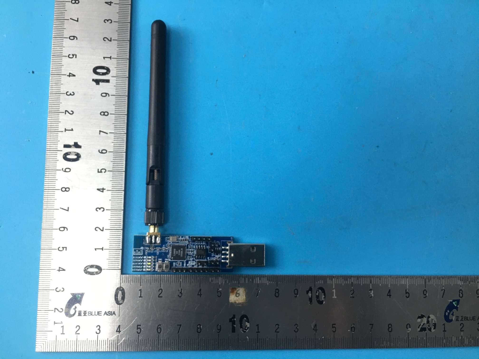
Click to zoom
Application Details
- Equipment Class
- DTS - Digital Transmission System
- Date of Grant
- Jun 16, 2024
- Application Purpose
- Original Equipment
- Date of Application
- Jun 16, 2024
- Equipment Note
- TLSR8208EDG56D
- Frequency Range
- 2402.00000000 - 2480.00000000
- Country
- China
Documents & Files
Document Text
Text extracted from the exhibit documents filed with the FCC. Open a document above to read the original.
Users Manual
Telink DONGLE TLSR8208EDG56D User Manual AN-24040700-E1 Ver.0.1.0 2024/04/07 Keyword Feature;2.4GHz; User manual Brief This is a user manual for Telink TLSR8208EDG56D DONGLE Telink DONGLE TLSR8208EDG56D user manual Telink Confidential and Proprietary 1 Ver.0.1.0 Published by Telink Semiconductor Bldg 3, 1500 Zuchongzhi Rd, Zhangjiang Hi-Tech Park, Shanghai, China © Telink Semiconductor All Right Reserved Legal Disclaimer The information contained in this document is confidential, privileged, and proprietary to Telink Semiconductor (Shanghai) Co, Ltd. and its related entities (“Telink”). The use and dissemination of this document is governed by the confidentiality/non-disclosure/disclaimer statement herein. Information in this document is intended for use by the intended recipient. This document may not be used, disclosed, published, disseminated, copied or distributed to any third party other than the intended recipient without the prior written consent of Telink which may be withheld in Telink’s sole discretion. Under no circumstances may this document be disclosed to a competitor of Telink. Any unauthorized use or disclosure is strictly prohibited. Copyright © 2020 Telink Semiconductor (Shanghai) Co., Ltd. Information For further information on the technology, product and business term, please contact Telink Semiconductor Company (www.telink-semi.com). For sales or technical support, please send email to the address of: [email protected] [email protected] Telink DONGLE TLSR8208EDG56D user manual Telink Confidential and Proprietary 2 Ver.0.1.0 Revision History Version Change Description V0.1.0 Initial release. Telink DONGLE TLSR8208EDG56D user manual Telink Confidential and Proprietary 3 Ver.0.1.0 Table of Contents Revision History ............................................................................................................................................................. 2 Table of Contents .......................................................................................................................................................... 3 1.Product Introduction ............................................................................................................................................... 4 1.1 GENERAL DESCRIPTION ......................................................................................................................................... 4 1.2 KEY FEATURES ................................................................................................................................................... 4 1.2.1 RF Features ............................................................................................................................................. 4 1.2.2 Chip Features .......................................................................................................................................... 4 1.2.3 Power Management Features ................................................................................................................... 4 1.2.4 Bluetooth LE Features .............................................................................................................................. 5 1.3 SUPPLY POWER .................................................................................................................................................. 5 1.4 DOWNLOAD FIRMWARE ........................................................................................................................................ 5 1.5 FUNCTIONS OF EACH MODULE ................................................................................................................................ 5 Telink DONGLE TLSR8208EDG56D user manual Telink Confidential and Proprietary 4 Ver.0.1.0 1.Product Introduction This is a user manual for Telink DONGLE TLSR8208EDG56D. 1.1 General description The Telink DONGLE TLSR8208EDG56D, which is based on Telink TLSR8208E chip. The TLSR8208E supports standards and industrial alliance specifications including Bluetooth low energy (LE). The embedded 2.4 GHz transceiver supports Bluetooth low energy as well as 2.4 GHz operation. 1.2 Key features 1.2.1 RF Features 1.Bluetooth/2.4 GHz RF transceiver in worldwide 2.4 GHz ISM band 2.Bluetooth LE 1 Mbps and 2 Mbps 3. Tx output power: up to +10 dBm 4. 2.4 GHz proprietary 1 Mbps/2 Mbps/250 kbps/500 kbps mode 5. RSSI monitoring with +/-1 dB resolution 6. RX sensitivity: -97 dBm @ Bluetooth LE 1 Mbps mode, -93 dBm @ Bluetooth LE 2 Mbps mode 1.2.2 Chip Features The TLSR8208E integrates a powerful 32-bit MCU, 2.4 GHz ISM radio, 16 KB OTP, 20 KB SRAM(16KB retention), external Flash, 14-bit Aux ADC, PWM, flexible IO interfaces, and other peripheral blocks required for IoT (Internet of Things) and HID (Human Interface Devices) application development. The TLSR8208E also includes multi-stage power management design allowing ultra-low power operation and making it the ideal candidate for power-constraint applications. 1.2.3 Power Management Features 1.Embedded LDO 2.Multiple stage power management to minimize power consumption . RF/Digit core working at 1.2 V 3.Low power consumption: . Whole chip RX mode: 9.1 mA with LDO . Whole chip TX mode @ 0 dBm: 9.5 mA with LDO . Deep sleep with external wakeup (without SRAM retention): 0.55 μ A . Deep sleep with 16 KB SRAM retention: 0.9 μ A . Deep sleep with external wakeup, with 32K RC oscillator on (without SRAM retention): 1.0 μA . Deep sleep with 16 KB SRAM retention, with 32K RC oscillator on: 1.3 μ A Telink DONGLE TLSR8208EDG56D user manual Telink Confidential and Proprietary 5 Ver.0.1.0 1.2.4 Bluetooth LE Features 1.Fully compliant with Bluetooth 5.3, main features supported include Bluetooth LE 1 Mbps and 2 Mbps 1.3 Supply power The TLSR8208EDG56D only supports supply power via USB(5V). As shown in figure 1-1, the marker is the USB port. Power can be supplied when USB is plugged in. Figure 1-1 USB powe…
Text truncated - open the document above for the full version.
Attestation Statements
AttestationStatements (date)2024/05/30 TO: Federal Communications Commission Authorization and Evaluation Division 7435 Oakland Mills Road Columbia, MD 21046, USA RE: Attestation Statements Part 2.911(d)(7) request for (FCC IDOEOTLSR8208EDG56D) (Telink Semiconductor (Shanghai) Co., Ltd.), the undersigned, hereby authorize(Baihetian Innovative Solutions) to act as our designated U.S. agent for service of process, (Telink Semiconductor (Shanghai) Co., Ltd. ) accepts to maintain an agent for no less than one year after the grantee has terminated all marketing and importation or the conclusion of any Commission-related proceeding involving the equipment.(Baihetian Innovative Solutions) accepts the responsibility to act as designated U.S. agent for service of process. Applicant Information: Company name:Telink Semiconductor (Shanghai) Co., Ltd. Contact Name:Xiang Li FRN:0021911706 Address:Bldg 3, No. 1500, Zuchongzhi Rd Zhangjiang Hi-tech Park Shanghai China Telephone No: +862120281118 Email: [email protected] Signature [name] U.S. Agent Information: Company Name:Baihetian Innovative Solutions Address:6837 Chase Rd Dearborn, MI 48126 FRN:0033401605 Contact Name:Kenneth Young Telephone No:313-395-3113 Email:[email protected] Signature [name]
ID Label/Location Info
Model No: TLSR8208EDG56D FCC ID: OEOTLSR8208EDG56D
Internal Photos
Product Name :TLSR8208EDG56D AppendixB:photographsofEUT
RF Exposure Info
SARevaluation ProductName: TLSR8208EDG56D FCCID: OEOTLSR8208EDG56D TestStandard: KDB447498D04GeneralRFExposure Guidancev01 Accordingto447498D04InterimGeneralRFExposureGuidancev01 StandaloneSARtestexclusionconsiderations UnlessspecificallyrequiredbythepublishedRFexposureKDBprocedures,standalone1-ghead orbodyand10-gextremitySARevaluationforgeneralpopulationexposureconditions,by measurementornumericalsimulation,isnotrequiredwhenthecorrespondingSARExclusion Thresholdcondition,listedbelow,issatisfied. CalculatedResultandLimit(WORSECASEISASBELOW) BLE Directional antennaGain (Numeric) PeakOutput Power(dBm) PeakOutput Power(mW) Limit(mW/cm²) TestResult 3dBi(1.995)7.429 5.532 (2402) 3060Compiles ERP=7.429+3-2.15=6.728mW<3060mW/cm²
Test Report
承认书 SPECIFICATION FOR APPROVAL Customer: Customer’s part number: Product description: 2.4G rubber duck Antenna Uni Link’s part number: KXWX-2.4G-Z Issue Date: 201911/07 Note: 2400-2500MHz,SMA male Customer Use Customer's authorized signature Remarks Full approved Conditional approved Rejected 一、产品参数 型 号 KXWX-433E-4 主要技术指标 频率范围(MHz) 2400-2500±5MHZ 频带宽度(MHz) 10 电压驻波比 ≤1.5 增益(dBi) 3 最大功率(W) 50 输入阻抗(Ω) 50 极化形式 垂直极化 天线尺寸(mm) 110+/-5 电缆长度(mm) 接口形式 SMA MALE Model Main Technical Specifications Frequency Range(MHz) 2400-2500±5 Bandwidth(MHz) 10 VSWR ≤1.5 Gain(dBi) 3 Max Input power(W) 50 Input Impedance(Ω) 50 Polarization Type Vertical Antenna Size(mm) 110+/-5 Line Length﹙mm﹚ Connector Type SMA MALE 二、产品规格 (Specifications) 1.电气测试 ( Electrical Characteristic ) ITEM 项目 TEST CONDITION 测试环境 SPECIFICATION 规格 1 电压驻波比 VSWR Using PROTEK A333 networking analyzer to measure Antenna S1 VSWR characteristics 使用PROTEK A333网路分析仪测试天线 S1之电压驻波比参数 PIC 1 2 阻抗 Smith Chart Using PROTEK A333 networking analyzer to measure Antenna S1 Smith Chart characteristics 使用PROTEK A333网路分析仪测试天线 S1之史密斯阻抗参数 PIC 2 3 增益响应 Gain Response Using PROTEK A333 networking analyzer to measure Antenna S1 Gain Response characteristics 使用PROTEK A333网路分析仪测试天线 S1之史密斯阻抗参数 2. 机械性能(MECHANICAL CHARACTERISTICS) 1 摇摆测试 BENDING TEST Put load 120g at the end of the wire, fixed joints, swaying test at an angle of 60 degrees , test features after 1000 times 放离接头30CM的线端上荷重120g,固 定接头后进行摇摆测试,左右角度各60 度,1000次后测试特性. No sign of damage 2 强度测试 STRENG TEST 15 pounds of static load applied to the bottom of the actinomycetes end for one minute. 一个15磅之静负荷施加放线端底部持续 一分钟. No sign of damage 3 拉力测试 PULLING FORCE Pull test with a tension meter between connector and wire 用拉力计接头及线材间进行拉力测试. No sign of damage 4 振动测试 VIBRATION TEST the X-axis direction for 120 minutes, and the Y-axis direction 120 minutes, the Z-axis direction 240 minutes as vibration testing of 1.1mm amplitude and 33.30Hz/sec of frequency 以1.10mm和振幅和33.30Hz/sec振动频率 以X轴方向振动120分钟,Y轴方向振动 120分钟,Z轴方向振动240分钟. No sign of damage 3. 耐久性测试(DURABILITY) 1 盐雾试验 SAIT SPRAY TEST 盐水喷雾试验:依GB1266-86标准 蒸馏水:一次蒸馏 PH6.5~7 喷雾量:1.4me80cm²/h 压缩空气压力:1Kgf/ cm² 试验相对度:98° 温度:45°~47° 压力温度:35° 测试时间:96hr 所有规格变华范 围初始值30% All characteristic range is 30% of the initial value 2 高温试验 HEAT TEST 在50 +/- 2 °C环境中放96小时,再放在正 常环境中30分钟后进行测试 50 +/- 2 °C for 96 hours, after keep in normal condition for 30mim the to test. 3 温试验 HUMIDITY TEST 在40+2°C 90-95%RH环境中放96小时, 再放在正常环境中30分钟后进行测试 40+2°C 90-95%RH for 96hours, after keep in normal condition for 30mim the to test. 4 低温试验 COLD TEST 在-40+2°C 环境中放96小时,再置放正常 环境中30分钟后进行测试 -40+2°C for 96hours, after keep in normal condition for 30mim the to test. PIC 1
Test Report
Website: www.cblueasia.com Tel: +86-755-23059481 Email: [email protected] The test report is effective only with both signature and specialized stamp and The result(s) shown in this report refer only to the sample(s) tested. Without written approval of BlueAsia, this report can’t be reproduced except in full. The results described in this report do not represent the quality or characteristics of the sampled batch, nor do they represent any similar or identical products that are not explicitly stated. Test Report Applicant : Telink Semiconductor (Shanghai) Co., Ltd. Address : Bldg 3, No. 1500, Zuchongzhi Rd,Zhangjiang Hi-tech Park,Shanghai,China. Product Name : TLSR8208EDG56D Brand Mark : TELINK Model : TLSR8208EDG56D FCC ID : OEOTLSR8208EDG56D Report Number : BLA-EMC-202404-A4701 Date of Receipt : 2024.04.23 Date of Test : 2024.04.23 to 2024.04.29 Test Standard : 47 CFR Part 15, Subpart C 15.247 Test Result : Pass Compiled by: Review by: Approved by: Issued Date: 2024.04.29 BlueAsia of Technical Services(Shenzhen) Co.,Ltd. Address: Building C, No. 107, Shihuan Road, Shiyan Sub-District, Baoan District, Shenzhen, Guangdong Province, China Report No.: BLA-EMC-202404-A4702 Page 2 of 69 BlueAsia of Technical Services (Shenzhen) Co.,Ltd. Tel: +86-755-23059481 Email: [email protected] www.cblueasia.com Table of Contents 1 General information ............................................................................................................................................... 4 1.1 General information ......................................................................................................................................... 4 1.2 General description of EUT ............................................................................................................................. 4 2 Test summary ......................................................................................................................................................... 5 3 Test Configuration .................................................................................................................................................. 6 3.1 Test mode ........................................................................................................................................................ 6 3.2 Operation Frequency each of channel ............................................................................................................ 7 3.3 Test channel ..................................................................................................................................................... 7 3.4 Configuration diagram of EUT ......................................................................................................................... 7 3.5 Auxiliary equipment ......................................................................................................................................... 8 3.6 Test environment ............................................................................................................................................. 8 4 Laboratory information .......................................................................................................................................... 9 4.1 Laboratory and accreditations ......................................................................................................................... 9 4.2 Measurement uncertainty ................................................................................................................................ 9 5 Test equipment ..................................................................................................................................................... 10 6 Test result .............................................................................................................................................................. 11 6.1 Antenna requirement ..................................................................................................................................... 11 6.2 Conducted emissions at AC power line (150 kHz-30 MHz) ........................................................................... 12 6.3 Conducted peak output Power ...................................................................................................................... 16 6.4 Minimum 6dB bandwidth ............................................................................................................................... 17 6.5 Power spectrum density ................................................................................................................................ 18 6.6 Conducted Band Edges Measurement .......................................................................................................... 19 6.7 Conducted spurious emissions ...................................................................................................................... 20 6.8 Radiated spurious emissions ......................................................................................................................... 21 6.9 Radiated emissions which fall in the restricted bands ................................................................................... 32 7 Appendix A ............................................................................................................................................................ 39 Appendix B: photographs of test setup ..................................................................................................................... 67 Appendix C: photographs of EUT ............................................................................................................................... 69 Report No.: BLA-EMC-202404-A4702 Page 3 of 69 BlueAsia of Technical Services (Shenzhen) Co.,Ltd. Tel: +86-755-23059481 Email: [email protected] …
Text truncated - open the document above for the full version.
Test Report
Report No.: BLA-EMC-202404-A4702 Page 31 of 69 BlueAsia of Technical Services (Shenzhen) Co.,Ltd. Tel: +86-755-23059481 Email: [email protected] www.cblueasia.com [Test mode: TX High channel]; [Polarity: Vertical] Test Result: Pass Report No.: BLA-EMC-202404-A4702 Page 32 of 69 BlueAsia of Technical Services (Shenzhen) Co.,Ltd. Tel: +86-755-23059481 Email: [email protected] www.cblueasia.com 6.9 Radiated emissions which fall in the restricted bands Test Standard 47 CFR Part 15, Subpart C 15.247 Test Method ANSI C63.10 (2013) Section 6.10.5 Test Mode (Pre-Scan) TX Test Mode (Final Test) TX 6.9.1 Limit Frequency(MHz) Field strength(microvolts/meter) Measurement distance(meters) 0.009-0.490 2400/F(kHz) 300 0.490-1.705 24000/F(kHz) 30 1.705-30.0 30 30 30-88 100 3 88-216 150 3 216-960 200 3 Above 960 500 3 Remark: The emission limits shown in the above table are based on measurements employing a CISPR quasi-peak detector except for the frequency bands 9-90kHz, 110-490kHz and above 1000 MHz. Radiated emission limits in these three bands are based on measurements employing an average detector, the peak field strength of any emission shall not exceed the maximum permitted average limits specified above by more than 20 dB under any condition of modulation. Report No.: BLA-EMC-202404-A4702 Page 33 of 69 BlueAsia of Technical Services (Shenzhen) Co.,Ltd. Tel: +86-755-23059481 Email: [email protected] www.cblueasia.com 6.9.2 Test setup Below 1GHz: 30MHz-1GHz: Above 1GHz: Report No.: BLA-EMC-202404-A4702 Page 34 of 69 BlueAsia of Technical Services (Shenzhen) Co.,Ltd. Tel: +86-755-23059481 Email: [email protected] www.cblueasia.com 6.9.3 Procedure a) For below 1GHz, the EUT was placed on the top of a rotating table 0.8 meters above the ground at a 3 or 10 meter semi-anechoic chamber. The table was rotated 360 degrees to determine the position of the highest radiation. b) For above 1GHz, the EUT was placed on the top of a rotating table 1.5 meters above the ground at a 3 meter fully-anechoic chamber. The table was rotated 360 degrees to determine the position of the highest radiation. c) The EUT was set 3 or 10 meters away from the interference-receiving antenna, which was mounted on the top of a variable-height antenna tower. d) The antenna height is varied from one meter to four meters above the ground to determine the maximum value of the field strength. Both horizontal and vertical polarizations of the antenna are set to make the measurement. e) For each suspected emission, the EUT was arranged to its worst case and then the antenna was tuned to heights from 1 meter to 4 meters (for the test frequency of below 30MHz, the antenna was tuned to heights 1 meter) and the rotatable table was turned from 0 degrees to 360 degrees to find the maximum reading. f) The test-receiver system was set to Peak Detect Function and Specified Bandwidth with Maximum Hold Mode. g) If the emission level of the EUT in peak mode was 10dB lower than the limit specified, then testing could be stopped and the peak values of the EUT would be reported. Otherwise the emissions that did not have 10dB margin would be re-tested one by one using peak, quasi-peak or average method as specified and then reported in a data sheet. h) Test the EUT in the lowest channel, the middle channel, the highest channel. i) The radiation measurements are performed in X, Y, Z axis positioning for Transmitting mode, and found the X axis positioning which it is the worst case. j) Repeat above procedures until all frequencies measured was complete. Note 1: Level (dBuV) = Reading (dBuV) + Factor (dB/m) Note 2: For frequencies above 1GHz, the field strength limits are based on average limits. However, the peak field strength of any emission shall not exceed the maximum permitted average limits specified above by more than 20 dB under any condition of modulation. For the emissions whose peak level is lower than the average limit, only the peak measurement is shown in the report. Report No.: BLA-EMC-202404-A4702 Page 35 of 69 BlueAsia of Technical Services (Shenzhen) Co.,Ltd. Tel: +86-755-23059481 Email: [email protected] www.cblueasia.com 6.9.4 Test data Remark: During the test, pre-scan the BLE1M/BLE2M mode, and found the BLE1M mode which it is worse case. [Test mode: TX low channel]; [Polarity: Horizontal] Test Result: Pass Report No.: BLA-EMC-202404-A4702 Page 36 of 69 BlueAsia of Technical Services (Shenzhen) Co.,Ltd. Tel: +86-755-23059481 Email: [email protected] www.cblueasia.com [Test mode:TX low channel]; [Polarity: Vertical] Test Result: Pass Report No.: BLA-EMC-202404-A4702 Page 37 of 69 BlueAsia of Technical Services (Shenzhen) Co.,Ltd. Tel: +86-755-23059481 Email: [email protected] www.cblueasia.com [Test mode: TX High channel]; [Polarity: Horizontal] Test Result: Pass Report No.: BLA-EMC-202404-A4702 Page 38 of 69 BlueAsia of Technical Services (Shenzhen) Co.,Ltd. Tel: +86-755-23059481 Email: [email protected] www.cblueasia.com [Test mode:TX High channel]; [Polarity: Vertical] Test Result: Pass Report No.: BLA-EMC-202404-A4702 Page 39 of 69 BlueAsia of Technical Services (Shenzhen) Co.,Ltd. Tel: +86-755-23059481 Email: [email protected] www.cblueasia.com 7 Appendix A Maximum Conducted Output Power Condition Mode Frequency (MHz) Antenna Conducted Power (dBm) Limit (dBm) Verdict NVNT BLE 1M 2402 Ant1 7.429 30 Pass NVNT BLE 1M 2442 Ant1 7.383 30 Pass NVNT BLE 1M 2480 Ant1 6.4 30 Pass NVNT BLE 2M 2402 Ant1 7.376 30 Pass NVNT BLE 2M 2442 Ant1 7.333 30 Pass NVNT BLE 2M 2480 Ant1 6.37 30 Pass Power NVNT BLE 1M 2402MHz Ant1 Power NVNT BLE 1M 2442MHz Ant1 Report No.: BLA-EMC-202404-A4702 Page 40 of 69 BlueAsia of Technical Services (Shenzhen) Co.,Ltd. Tel: +86-755-23059481 Email: [email protected] www.cblueasia.com Power NVNT BLE 1M 2480MHz Ant1 Power NVNT BLE 2M 2402MHz Ant1 Report No.: BLA-EMC-202404-A4702 Page 41 of 69 BlueAsia of Technical Services (Shenzhen) Co.,Ltd. Tel: +86-755-230594…
Text truncated - open the document above for the full version.
Test Setup Photos
Product Name :TLSR8208EDG56D ConductedemissionsatACpowerline(150kHz-30MHz) RadiatedEmissions(30MHz-1GHz) RadiatedEmissions(above1GHz)
Contact Information
Applicant
Xiang Li
Test Firm
BlueAsia of Technical Services (Shenzhen)Blue Zheng
[email protected]+86 755-23059481-815
Technical Specifications
| # | Rule Parts | Frequency Range | Power Output |
|---|---|---|---|
| 1 | 15C | 2.40 GHz - 2.48 GHz | 5.53 mW |
Other Applications from Telink Semiconductor (Shanghai) Co., Ltd.
OEOTL3228XDG96D
Jul 14, 2026TL3228XDG96D
Equipment Class
DTS - Digital Transmission System
OEOTL3228XDK96D
Jun 01, 2026TL3228XDK96D
Equipment Class
DTS - Digital Transmission SystemOEOM3228AMRM0
Apr 14, 2026ML3228A-GAIA-M3-PE11
Equipment Class
DTS - Digital Transmission System
OEOTLSR8208EDK56D
Jun 16, 2024TLSR8208EDK56D
Equipment Class
DTS - Digital Transmission System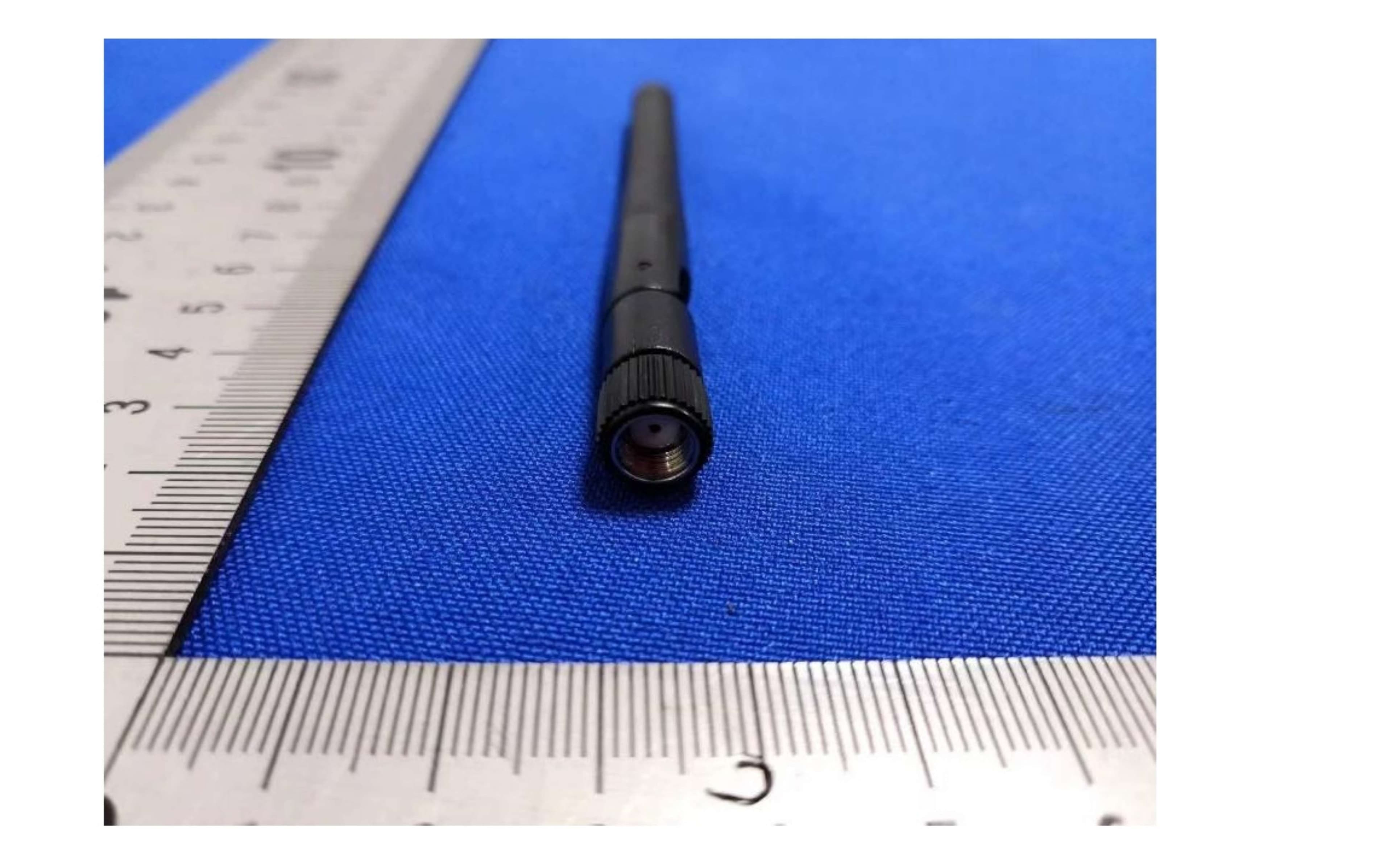
OEOTLSRSOCSG80R-1
Jan 14, 2024Telink RF Dongle-V1
Equipment Class
DTS - Digital Transmission System