OEUHPA460M250WPower Series 1, 250W, 450-470MHZ RF Power Amplifie
TRL Technologies, Inc.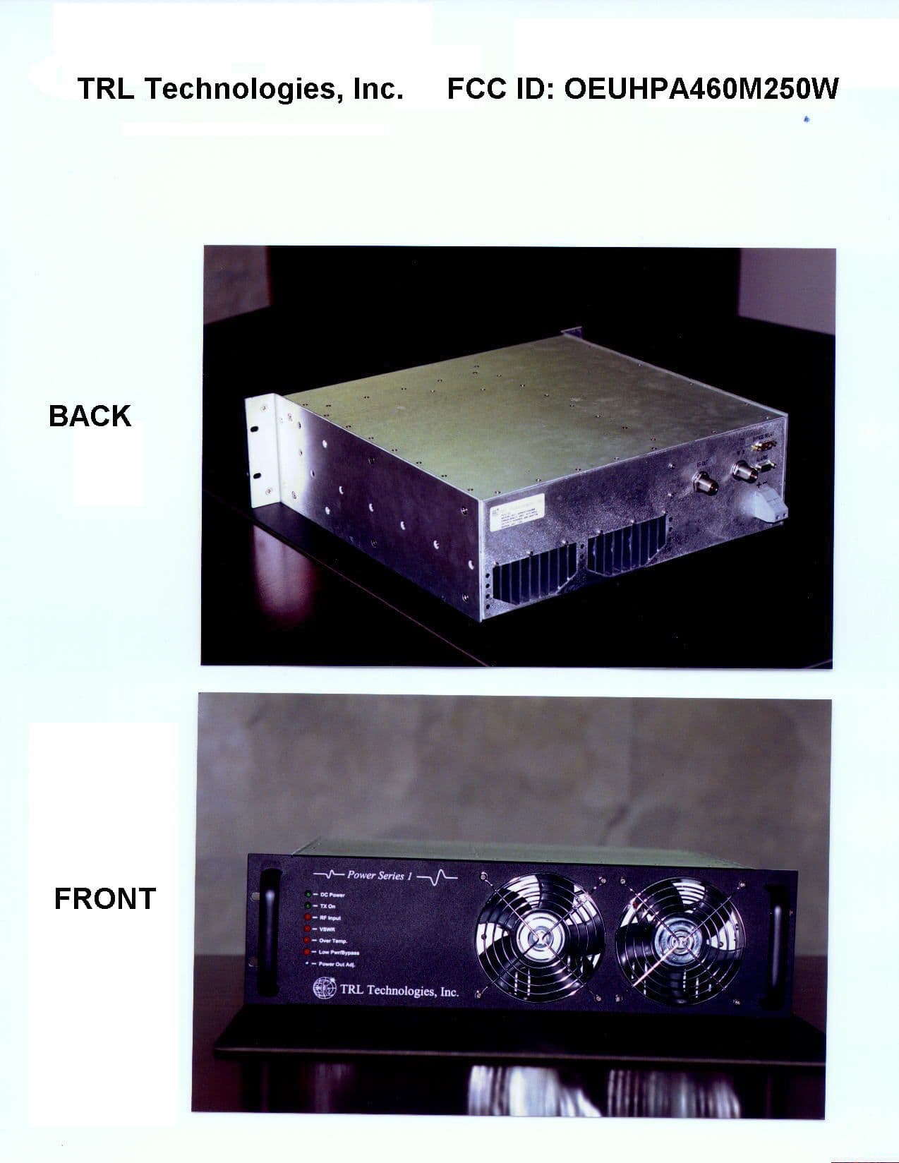
Click to zoom
Application Details
- Equipment Class
- AMP - Amplifier
- Date of Grant
- Apr 05, 1999
- Application Purpose
- Original Equipment
- Date of Application
- Feb 08, 1999
- Equipment Note
- Power Series 1, 250W, 450-470MHZ RF Power Amplifie
- Frequency Range
- 450.00000000 - 470.00000000
- Company
- TRL Technologies, Inc.
- Country
- United States
Documents & Files
Document Text
Text extracted from the exhibit documents filed with the FCC. Open a document above to read the original.
Users Manual
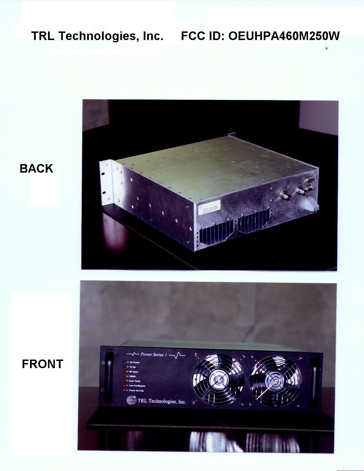
TRL TECHNOLOGIES, INC.FCC ID: OEUHPA460M250W PAGE 1 OF 2 POWER SERIES 1 250W 450-470MHZ RF POWER AMPLIFIER USER MANUAL 1. GENERAL DESCRIPTION The Power Series 1 250W, 450-470MHz Power Amplifier is a high power amplifier (PA) that incorporates LDMOS technology to provide high efficiency and rugged operation. It is developed for paging or trunking application. The PA features various alarms and protection circuitry, Automatic Level Control (ALC) and cooling fans. 2. INSTALLATION Make sure the PA’s output port is appropriately terminated before applying any RF input signal. Connect the RF input signal to the PA’s input port labeled RF IN. Connect the PA’s output port labeled RF OUT to the optional RF Bypass Relay Module or an antenna. Connect a DC power supply source to the connector labeled + -. Apply the required DC voltage (26-28V, 810W). After going through an initialization state, the PA’s DC POWER LED (green) and RF INPUT LED (red) should be on. Apply the RF input signal (25-50W, 450-470MHZ). RF INPUT LED should turn off. TX ON LED (green) should turn on. The PA is now transmitting. Monitor the RF output. Adjust the RF output level, via the Power Out Adj pot from the front panel for 250W. 3. SPECIFICATIONS Electrical Frequency Range:450-470 MHz Output Power:250 Watts (max) RF Output Power Dynamic Range:3dB (min) (125 Watts) ALC Settling Time:100ms max to within ± 1dB of final value Input Power:25 Watts (min) 35 Watts (nominal) 50 Watts (max) Input Return Loss:-14.0 dB (max) Harmonics & Spurious:-70dBc (max) Stability:Under 3:1 VSWR DC Supply Voltage:26-28 V Input DC Power:810 Watts (maximum) TRL TECHNOLOGIES, INC.FCC ID: OEUHPA460M250W PAGE 2 OF 2 RF Load VSWR:Full power at better than 2:1 VSWR Environmental Operating Temp:-30 to 45°C Humidity:0-95% relative humidity, no condensing Operating Altitude:0-12,000 feet Mechanical Cooling Fan:Internal fan, front to rear
ID Label/Location Info
TRL TECHNOLOGIES, INC.FCC ID: OEUHPA460M250W ID LABEL LOCATION S ER IAL N O .: 10 0 O U TP U T P O W E R : 2 5 0 W ATTS FREQUENC Y: 450 - 470 M Hz M ODEL NO.: A250070406B FCC ID: BYPASS RELAY R F O U TR F IN + - ALARM TRL TECHNOLOGIES, INC.FCC ID: OEUHPA460M250W ID LABEL SERIAL NO.: 100 OUTPUT POWER: 250 WATTS FREQUENCY: 450 - 470 M Hz MODEL NO.: A250070406B FCC ID:
ID Label/Location Info
TRL TECHNOLOGIES, INC.FCC ID: OEUHPA460M250W PAGE 1 OF 1 FCC ID: OEUHPA460M250W MODEL NO.: A250070406B FREQUENCY: 450 - 470 MHz OUTPUT POWER: 250 WATTS SERIAL NO: 2000 BYPAS S RELAY RF OUTRF IN + - ALARM SERIAL NO: 2000 OUTPUT POWER: 250 WATTS FREQUENCY: 450 - 470 M Hz M ODEL NO.: A250070406B FCC ID: OEUHPA460M 250W
Operational Description
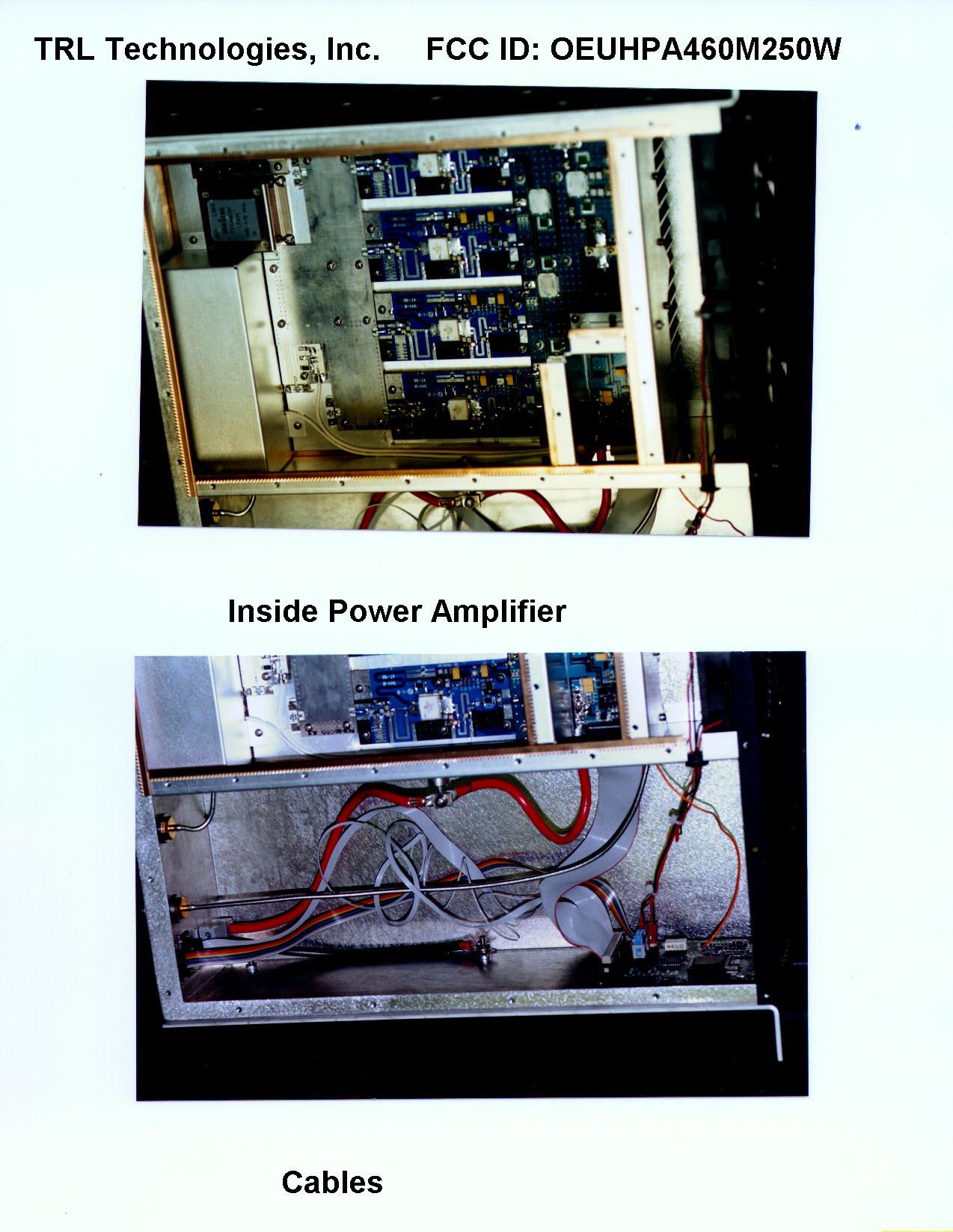
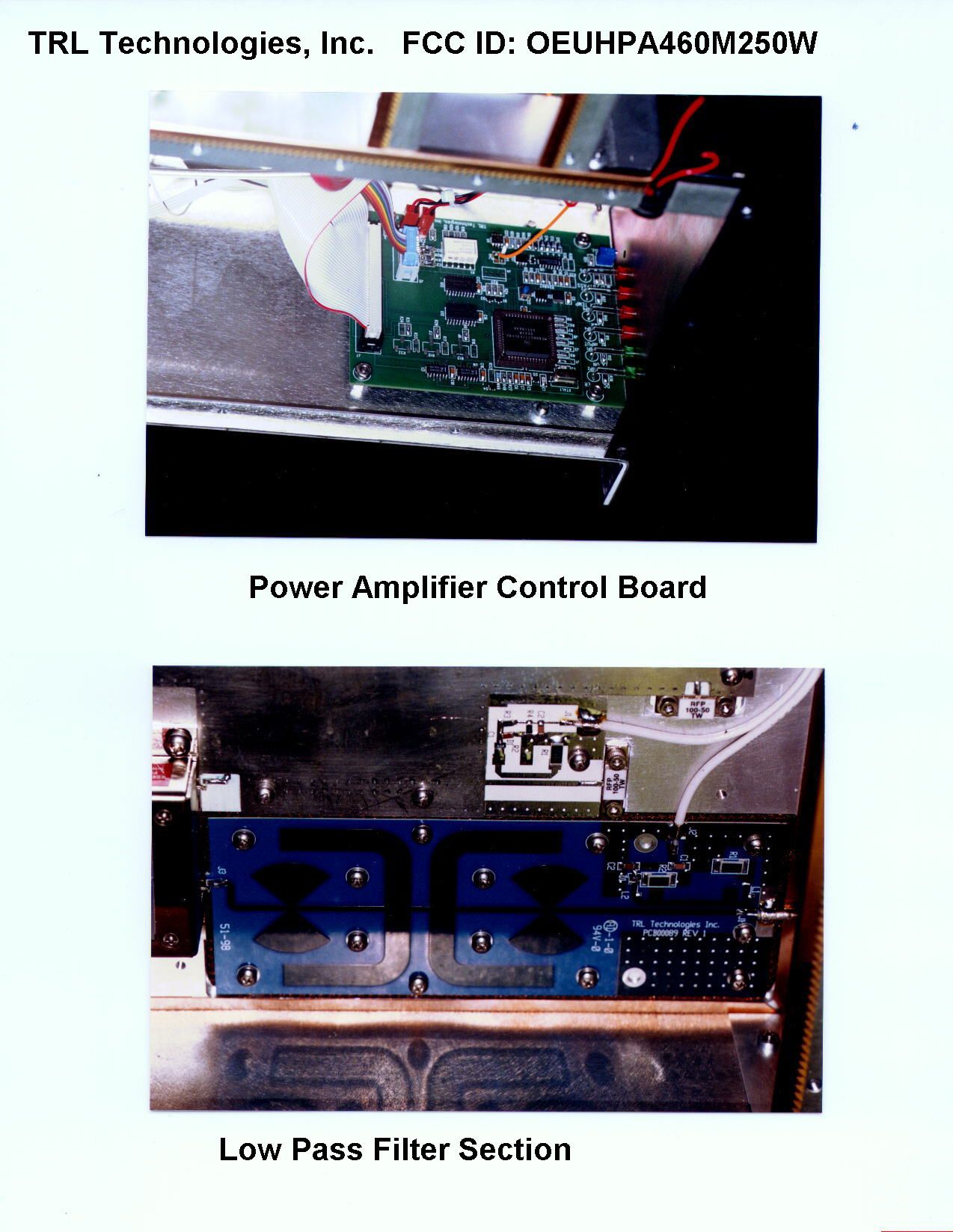
TRL TECHNOLOGIES, INC.FCC ID: OEUHPA460M250W PAGE 1 OF 4 OPERATIONAL DESCRIPTION 1. DESCRIPTION a) Individual Stages The Power Series 1 250W Power Amplifier is divided into the following sections: • Driver Stage: includes attenuation network and intermediate power amplification. The attenuation level is varied via an AGC line. A 30W LDMOS power transistor amplifies the RF signal to an intermediate level. The RF signal then goes through several 3dB hybrid splitters. • Final Stage: consists of 4 100W LDMOS power transistors that further amplify the RF signal to a final level before it gets recombined at the output. • Strip Line Combiner • Circulator: provides protection for the PA. • Lowpass filter: suppresses the harmonic spur at the PA output. • PA Control: contains input signals, microprocessor and output signals sections. b) Overall Lineup The RF input is fed through an attenuation network before being routed to a driver amp. The driver amp’s output is then passed through a series of 3dB hybrid splitters/combiners to have the signal split into 4 equally signals. These 4 output signals are then fed to 4 separate final amps. A strip line combiner is used to combine all 4 signals. The final result is passed through a circulator and then a low pass filter before going out to the PA’s output port. Refer to the PA Lineup Diagram. There are sensors and couplers placed through out the PA to monitor the PA’s input level, forward and reflected power output levels, as well as the ambient and heat sink temperature. There is also coupler to detect any final amps failure. These sensor and coupler voltages are utilized by the on-board HC11 microprocessor to provide various PA alarm and protection. Refer to the PA Control Diagram. 2. FEATURES The 250W Power Series 1 PA provides numerous alarm monitor and protection features. a) Fold Back Mode The PA will go to the Fold Back Mode and reduce its power by 3dB (125W) when • Load VSWR is between 2:1 to 3:1 • Ambient temperature is between 45 to 60°C b) Bypass Mode The Bypass Mode is available when the PA is used in conjunction with an optional relay box. The PA will automatically switch to the Bypass Mode and take itself out of the system’s lineup when any of the following conditions is true: • Input power is greater than 50 Watts TRL TECHNOLOGIES, INC.FCC ID: OEUHPA460M250W PAGE 2 OF 4 • Any final amp pallets fail • Ambient temperature is greater than 60°C • Heat sink temperature is greater than 90°C • Load reflection is greater than 3:1 VSWR • DC supply voltage is less than 22V or greater than 30V • Output power is less than 125W c) Alarm Indicators Note: When the PA is used without the optional RF Bypass Relay Module, the Low Pwr/Bypass LED represents a low power output condition. Otherwise, the LED indicates whether the PA is operated in the Bypass Mode. AlarmsLED StatusCondition DC PowerSolid Green LED Flashing Off Between 25V-28V Greater than 28V but less than 30V or Greater than 22V but less than 25V Less than 22V or Greater than 30V or No power at all TX OnSolid Green LED Off PA is transmitting PA is not transmitting RF InputSolid Red LED Flashing Off No input power Over/Under limit Input power is within limit High VSWR Solid Red LED Off Greater than 2:1 VSWR No alarm Over TempSolid Red LED Flashing Off Ambient Temp is greater than 60°C or Heat sink Temp is greater than 90°C Ambient Temp is greater than 45°C but less than 60°C No alarm Low Pwr /Bypass Solid Red LED Off PA is being bypassed or power output is below 125W PA is in operation Table 1. Alarms 3. INTERFACE SIGNALS Pin #Signals 1Low output power/Bypass (0V-no fault, 5V-fault) 2Over temperature (0V-no fault, 5V-fault) 3Input Power (0V-no fault, 5V-fault) 4Form C relay, NC 5Form C relay, NO 6Ground 7VSWR (0V-no fault, 5V-fault) 8External Reset 9Form C relay, COMMON TRL TECHNOLOGIES, INC.FCC ID: OEUHPA460M250W PAGE 3 OF 4 Table 2. DB9 Alarms Out Connector Alarms out connector provides external monitor and control capabilities. Pin #Signals 1Power Supply 26.5V 2Ground 3TTL Relay Input 4NC 5NC 6Power Supply 26.5V 7Ground 8TTL Relay Output 9NC Table 3. DB9 Relay Bypass Connector INPUT V_RF IN V_FWD V_RFL V_DUMP LOAD DC VOLTAGE HEAT SINK TEMP AMBIENT TEMP OUTPUT DC POWER TX ON RF INPUT VSWR OVER TEMP HEAT SINK TEMP AMBIENT TEMP PWR OUT ADJUST CONTROL FIGURE 1. PA CONTROL DIAGRAM TRL TECHNOLOGIES, INC. FCC ID: OEUHPA460M250W PAGE 4 OF 4 FINAL TEMP SENSOR LPF V_FWD V_ DUMP LOAD AGC AMP2AMP3 AMP SPLITTER AMP1 SPLITTER STRIPLINE COMBINER SIGNAL OUTV_FWDV_RFLHEAT SINK TEMPV_DUMP LOADDC VOLTAGEAMBIENT TEMP RF IN RF OUT LPF AMP4 V_RF IN V_ DUMP LOAD AGC AMP2AMP3 ATTENUATOR AMP DRIVER SPLITTER SPLITTER HEAT SINK TEMP V_RFL AMP1 STRIPLINE COMBINER SIGNAL OUTV_FWDV_RFLHEAT SINK TEMPV_DUMP LOADDC VOLTAGEAMBIENT TEMP RF IN RF OUT V_FWD CIRCULATOR FIGURE 2. PA LINEUP DIAGRAM
Parts List/Tune Up Info
TRL TECHNOLOGIES, INC. FCC ID: OEUHPA460M250W PART LIST Driver Amp ItemDescriptionPart #Reference 1Temperature SensorLM50BU12 2Positive Voltage Regulator, Fixed, 15V, 3AMC78T15CTU1 3Positive Voltage Regulator, Fixed, +5V, 3AMC78T05CTU8 4Pin Diode, High PowerMA4P4006FD2, D3, D4, D5 5Coupler, Anaren, 90 Deg. Hybrid11303-3H1, H2, H3, H4 6Diode, Detector, HP, HSM2800HSM2800D1 Final Amp ItemDescriptionPart #Reference 1Diode, Zener, 30V1SMB5936BT3D1 2LDMOS Power Transistor, 100 WattXRF187SQ1 3Regulator, 15VLM78L15U1 Combiner ItemDescriptionPart #Reference 1Diode, Detector, HP, HSMS2800HSMS2800D1 Control Board ItemDescriptionPart #Reference 1 Diode, Dual Zener, 5.6VMMBZ5V6ALT1 D1,D2,D3 2Diode, Zener, 12VMMBZ5242BLD4 3D/A ConverterMAX534U2 4Dual ComparatorLM293DU17 5 Hex, Non InverterMC74HC241ADW U12,U13 6MCUMC68HC711E9CFN2U1 7Dual OP AMP, High CurrentMC33076DU4 8Quad OP AMPMC33204DU3,U9 9Serial InterfaceDS14C232CMU8 10Undervolt SenseMC34164D-5U6 11Precision Reference Voltage, 5VLM4040DAIM3-5.0D5 12 XTAL 8MHZ AS-8.000-18-SMD XTAL1 LPF ItemDescriptionPart #Reference 1Diode, Detector, HP, HSMS2800HSMS2800D1 Circulator Load ItemDescriptionPart #Reference 1Diode, Detector, HP, HSMS2800HSMS2800D1 2Thermistor, 10K10KRT1 Final Assembly ItemDescriptionPart #Reference 1Positive Voltage Regulator 15V, Fixed, 3AMC78T15CTU1 2Positive Voltage Regulator 5V, Fixed, 3AMC78T05CTU8 3Diode70HFR60 4Circulator 440-470MHz 5LDMOS Power Transistor, 30 WattMRF182Q1 PAGE 1 OF 1
Parts List/Tune Up Info
TRL TECHNOLOGIES, INC.FCC ID: OEUHPA460M250W PAGE 1 OF 1 TUNE UP PROCEDURE The PA’s power out is factory set at 250W. The following power adjustment procedure is provided for reference or verification purpose: • Connect the PA’s input port to a RF source. • Connect the PA’s output port to a 50Ohm, 250W load. • Connect the PA’s DC input to a 20A DC voltage source. • Apply a 27VDC. • Apply a RF frequency between 450-470MHZ and amplitude between 25 to 50W . • Adjust the power out adjust pot located on the front panel for 250W. DC SUPPLY RF SOURCE LOAD COUPLER POWER METER PA
Schematics
TRL TECHNOLOGIES, INC.FCC ID: OEUHPA460M250W DRIVER AMP SCHEMATICSPAGE 5 OF 7
Schematics
TRL TECHNOLOGIES, INC. FCC ID: OEUHPA460M250W CIRCULATOR LOAD SCHEMATICS PAGE 1 OF 7
Schematics
TRL TECHNOLOGIES, INC. FCC ID: OEUHPA460M250W CONTROL BOARD, SIGNALS IN SCHEMATICS PAGE 2 OF 7
Schematics
TRL TECHNOLOGIES, INC. FCC ID: OEUHPA460M250W CONTROL BOARD, MICROPROCESSOR SCHEMATICS PAGE 3 OF 7
Schematics
TRL TECHNOLOGIES, INC. FCC ID: OEUHPA460M250W CONTROL BOARD, SIGNALS OUT SCHEMATICS PAGE 4 OF 7
Schematics
TRL TECHNOLOGIES, INC. FCC ID: OEUHPA460M250W FINAL AMP SCHEMATICS PAGE 6 OF 7
Schematics
TRL TECHNOLOGIES, INC. FCC ID: OEUHPA460M250W LPF SCHEMATICS PAGE 7 OF 7
Test Report
TRL TECHNOLOGIES, INC. FCC ID: OEUHPA460M250W SIGNAL GENERATOR HP8648E LNA GRF5064 CIR ATTENUATOR HPF SPECTRUM ANALYZER HP8561E DUT Conducted Spurious Measurement Test Setup The Signal generator supplies a low RF level that is amplified, by the LNA, to a suitable inputRF level to the PA.The HPF provides the necessary dynamic level for the input to the spectrum analyzer.measurement.
Test Report
TRL TECHNOLOGIES, INC. FCC ID: OEUHPA460M250W SUMARY SHEET FOR CONDUCTED SPURIOUS EMISSIONS TEST 1. Test Setup 2. Test Data DUT250W, 450-470MHZ RF Power Amplifier ManufacturerTRL Technologies, Inc. Model #A250070406B S/N000 Test DateFebruary 8, 1999 Rated Power250 Watts Measured Power250 Watts Test Results: FREQ INMETER READING CABLE/PADS & FILTER LOSSES TOTALFCC LIMIT MARGIN MHzdBmdBdBmdBmdB 920-56.83-32.2-24.63-1311.63 1380-65.67-32.4-33.27-1320.27 1840-66.67-32.7-33.97-1320.97 2300-63.83-32.9-30.93-1317.93 2760-73.33-33.2-40.13-1327.13 3220-71.83-32.5-39.33-1326.33 3680-68.17-31.3-36.87-1323.87 4140-73.33-29.4-43.93-1330.93 4600-73.67-53.5-20.17-137.17 Conclusion: All data is within FCC specification 3. Test Equipment Equipment NameManufacturerModel #Serial # LNAOPHIR RFGRF50641006 Power MeterHP438A2743A04697 Power SensorHP8481B3318A08142 Power SensorHP8482B2703A03328 Signal GeneratorHP8648E3537A02176 Spectrum AnalyzerHP8561E3626A01558 SIGNAL GENERATOR HP8648E LNA GRF5064 CIR ATTENUATOR HPF SPECTRUM ANALYZE R HP8561E DUT
Test Report
TRL TECHNOLOGIES, INC.FCC ID: OEUHPA460M250W 2 ND HARMONIC SPUR CONDUCTED SPUR DATAPAGE 1 OF 9
Test Report
TRL TECHNOLOGIES, INC.FCC ID: OEUHPA460M250W 8 TH HARMONIC SPUR CONDUCTED SPUR DATAPAGE 3 OF 9
Test Report
TRL TECHNOLOGIES, INC.FCC ID: OEUHPA460M250W 4 TH HARMONIC SPUR CONDUCTED SPUR DATAPAGE 3 OF 9
Test Report
TRL TECHNOLOGIES, INC.FCC ID: OEUHPA460M250W 5 TH HARMONIC SPUR CONDUCTED SPUR DATAPAGE 4 OF 9
Test Report
TRL TECHNOLOGIES, INC.FCC ID: OEUHPA460M250W 6 TH HARMONIC SPUR CONDUCTED SPUR DATAPAGE 5 OF 9
Test Report
TRL TECHNOLOGIES, INC.FCC ID: OEUHPA460M250W 7 TH HARMONIC SPUR CONDUCTED SPUR DATAPAGE 6 OF 9
Test Report
TRL TECHNOLOGIES, INC.FCC ID: OEUHPA460M250W 8 TH HARMONIC SPUR CONDUCTED SPUR DATAPAGE 7 OF 9
Test Report
TRL TECHNOLOGIES, INC.FCC ID: OEUHPA460M250W 9 TH HARMONIC SPUR CONDUCTED SPUR DATAPAGE 8 OF 9
Test Report
TRL TECHNOLOGIES, INC.FCC ID: OEUHPA460M250W 10 TH HARMONIC SPUR CONDUCTED SPUR DATAPAGE 9 OF 9
Contact Information
Applicant
Hiep Lam(Electrical Engineer)
Test Firm
Elite Electronic Engineering Co.Daniel Crowder
Technical Specifications
| # | Rule Parts | Frequency Range | Power Output | Emission | Tolerance |
|---|---|---|---|---|---|
| 4 | 9 | 450 MHz - 470 MHz | 250 W | F3E | Amp |
Other Applications from TRL Technologies, Inc.

OEUB8001900-1C
Jul 05, 2005Wireless In-Vehicle Cellular Signal Enhancer
Equipment Class
AMP - Amplifier
OEUB851-1A
Jun 09, 2005iDEN Wireless Compensator
Equipment Class
AMP - Amplifier
OEUBDA1900-2
Oct 24, 2004In-Home Cellular Signal Enhancer
Equipment Class
PCB - PCS Licensed Transmitter
OEUB8001900-1A
Sep 21, 2004Wireless In-Vehicle Cellular Signal Enhancer
Equipment Class
PCB - PCS Licensed Transmitter
OEUB8001900-1
Aug 15, 2004Wireless In-Vehicle Cellular Signal Enhancer
Equipment Class
PCB - PCS Licensed Transmitter