OEUPA882M180WBase station RF Power Amplifier
TRL Technologies, Inc.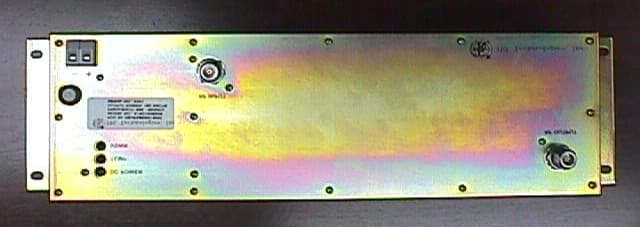
Click to zoom
Application Details
- Equipment Class
- AMP - Amplifier
- Date of Grant
- Jun 08, 1999
- Application Purpose
- Original Equipment
- Date of Application
- Mar 17, 1999
- Equipment Note
- Base station RF Power Amplifier
- Frequency Range
- 869.00000000 - 894.00000000
- Company
- TRL Technologies, Inc.
- Country
- United States
Documents & Files
Document Text
Text extracted from the exhibit documents filed with the FCC. Open a document above to read the original.
Users Manual
TRL TECHNOLOGIES, INC.FCC ID: OEUPA882M180W PAGE 1 OF 2 RF IN RF OUT 180W 869-894MHZ RF POWER AMPLIFIER USER MANUAL 1. GENERAL DESCRIPTION The 180W 869-894MHz Power Amplifier is a high power amplifier (PA) that incorporates LDMOS technology to provide high efficiency and rugged operation. The PA features a compact housing, alarm display LEDs and cooling fan. 2. INSTALLATION Figure 1. Front Display and Connections • Connect the PA’s RF IN port to a RF source. • Terminate the PA’s RF OUT port with a 180W 50Ohm load. • Connect a DC power supply source to the terminal block labeled + -. • Turn on the DC power supply and set for 26V. The PA’s DC POWER LED and cooling fan should be on. • Turn on the RF signal. Monitor the input and output power. Increase the RF input level gradually until 180W is obtained at the PA’s RF OUT port. The RF input level should remain less than 20W. 3. SPECIFICATIONS Electrical Frequency Range869-894 MHz Output Power180 Watts max ALC Settling Time100ms max to within ± 1dB of final value Input Power20 Watts max - + DC POWER TEMP VSWR FUSE TRL TECHNOLOGIES, INC.FCC ID: OEUPA882M180W PAGE 2 OF 2 Input Return Loss-10 dB Harmonics & SpuriousBetter than -70dBc StabilityLess than 3:1 VSWR DC Supply Voltage26 V ± 0.5 V Input DC Power520 Watts RF Load VSWRFull power at better than 2:1 VSWR Environmental Operating Temp:-30 to 45 ° C Humidity:0-95% relative humidity, no condensing Operating Altitude0-12,000 feet Mechanical CoolingSingle external fan, forced air along the sides
External Photos
TRL TECHNOLOGIES, INC.FCC ID: OEUPA882M180W PAGE 1 OF 2 FRONT BACK
ID Label/Location Info
TRL TECHNOLOGIES, INC.FCC ID: OEUPA882M180W PAGE 1 OF 1 SERIAL N O : 2000 O U TPU T PO W ER: 180 W ATTS FREQ U EN C Y: 869 - 894M Hz M O D EL N O .: A180100882B F C C ID : O E U P A 8 8 2 M 1 8 0 W DC POW ER TEM P VSW R + _ RF INPUT RF OUTPUT FCC ID: O EU PA882M 180W MODEL NO.: A180100882B FR EQ U EN C Y: 869 - 894M Hz OUTPUT POW ER: 180 W ATTS SERIAL NO: 2000
Internal Photos
TRL TECHNOLOGIES, INC.FCC ID: OEUPA882M180W PAGE 2 OF 2
Operational Description
TRL TECHNOLOGIES, INC.FCC ID: OEUPA882M180W PAGE 1 OF 2 OPERATIONAL DESCRIPTION 1. DESCRIPTION a) Individual Stages The Power Amplifier is divided into the following sections: • Splitter Stage: includes DC supply regulation, display LEDs, splitter and temperature sensor. • Amplification Stage: consists of two 125W final amplifier pallets. • Combiner Stage: consists of VSWR monitor circuitry, combiner, circulator and low pass filter. b) Overall Lineup The RF input is fed to a 3dB splitter and amplified by 2 final PA pallets. The 2 signals are then recombined and routed to a circulator and then a low pass filter before going out to the PA’s output port. A temperature sensor locating on the driver board monitors the PA’s heat sink temperature. Temp LED display will turn on when the heat sink temperature is exceeded 65°C. The PA’s Output VSWR level is monitored at the circulator load. VSWR LED display will turn on when the output VSWR is approximately 3:1. SignalsLEDCondition DC PowerGreenDC power is on VSWRRedGreater or equal to 3:1 VSWR at the output TempRed Ambient Temp is at least 65°C Table 1. LED Display TRL TECHNOLOGIES, INC. FCC ID: OEUPA882M180W PAGE 2 OF 2 FINAL TEMP SENSOR LPF V_ DUMP LOAD AGC AMP1 STRIPLINE COMBINER V_FWDV_RFL RF IN RF OUT AMP2 DRIVER SPLITTER TEMP VSWR LEDSDC POWERVSWRTEMP RF OUT CIRCULATOR
Parts List/Tune Up Info
TRL TECHNOLOGIES, INC. FCC ID: OEUPA882M180W PART LIST Splitter ItemDescriptionPart # Reference 1Temperature SensorLM35DU4 2Transistor, NPNMMBT3904Q1-2 3Splitter, Quadrature, SMTS03A888N1H1 4Diode, SchottkyHSMS2800D1 5Dual OP-AMPMC33172DU3 6Regulator, 5VMC78T05CTU1 7Regulator, 15VMC78T15CTU2 Final Amp ItemDescriptionPart # Reference 1RF TransistorPTF10020U3 2Regulator, 15V78L15ACMU1 Combiner/Circulator/ LPF ItemDescriptionPart # Reference 1Coupler, QuadratureRFP-915-90-400-201H1 2Diode, SchottkyHSMS2800D1-2 3Circulator, 869-894MHZ 200WDF1193FIL1 PAGE 1 OF 1
Parts List/Tune Up Info
TRL TECHNOLOGIES, INC.FCC ID: OEUPA882M180W PAGE 1 OF 1 TUNE UP PROCEDURE 1. Equipments • Directional coupler • RF load • DC power supply • Power meter 2. Tuning Procedure • Connect the PA’s input port to a RF source. • Terminate the PA’s output port with a 50Ohm, 180W load. • Connect the PA’s DC input to a DC voltage source (520W). • Turn on the DC supply and set for 26VDC. • Apply a RF frequency between 869-894MHZ. Monitor input and output power. Slowly increase the input amplitude until a 180W is reached at the output. The input level should remain less than 20W. DC SUPPLY RF SOURCE LOAD COUPLER POWER METER PA COUPLER COUPLER POWER METER
Schematics
TRL TECHNOLOGIES, INC. FCC ID: OEUPA882M180W PAGE 1 OF 4
Schematics
TRL TECHNOLOGIES, INC. FCC ID: OEUPA882M180W PAGE 2 OF 4
Schematics
TRL TECHNOLOGIES, INC. OEUPA882M180W PAGE 3 OF 4
Schematics
TRL TECHNOLOGIES, INC. FCC ID: OEUPA882M180W PAGE 4 OF 4
Test Report
TRL TECHNOLOGIES, INC.OEUPA882M180W Page 1 of 3 1.0 TEST SETUP The PA’s frequency was set to 881.5MHz and FM modulated with a 3 kHz 50% duty cycle square wave at a 5kHz deviation. The output power was set to 180W. 2.0 RESULTS In accordance with paragraph 22.917 (d) the peak power of any emission shall be attenuated below the unmodulated carrier power (P) in accordance with the following: (1) On any frequency removed from the carrier frequency by more than 20kHz but not more than 45kHz: At least 26dB. (2) On any frequency removed from the carrier frequency by more than 45kHz but not more than 90kHz: At least 45dB. (3) On any frequency removed from the carrier frequency by more than 45kHz, up to the first multiple of the carrier frequency: at least 60dB or 43 + 10log(P)dB, whichever is the lesser attenuation. The occupied bandwidth measurement results were plotted in figure 1 and 2. The limits are referenced to the power measured from the unmodulated carrier. As can be seen from the data, the sideband emissions measured at the output were similar to the sideband emissions measured from the input. TRL TECHNOLOGIES, INC.OEUPA882M180W Page 2 of 3 Figure 1. Input Spectrum TRL TECHNOLOGIES, INC.OEUPA882M180W Page 3 of 3 Figure 2. Output Spectrum
Contact Information
Applicant
Hiep Lam(Electrical Engineer)
Test Firm
Elite Electronic Engineering Co.Daniel Crowder
Technical Specifications
| # | Rule Parts | Frequency Range | Power Output | Emission | Tolerance |
|---|---|---|---|---|---|
| 2 | 22H | 869 MHz - 894 MHz | 180 W | F8W | Amp |
Other Applications from TRL Technologies, Inc.

OEUB8001900-1C
Jul 05, 2005Wireless In-Vehicle Cellular Signal Enhancer
Equipment Class
AMP - Amplifier
OEUB851-1A
Jun 09, 2005iDEN Wireless Compensator
Equipment Class
AMP - Amplifier
OEUBDA1900-2
Oct 24, 2004In-Home Cellular Signal Enhancer
Equipment Class
PCB - PCS Licensed Transmitter
OEUB8001900-1A
Sep 21, 2004Wireless In-Vehicle Cellular Signal Enhancer
Equipment Class
PCB - PCS Licensed Transmitter
OEUB8001900-1
Aug 15, 2004Wireless In-Vehicle Cellular Signal Enhancer
Equipment Class
PCB - PCS Licensed Transmitter