OEUPA882M180WS2Base Station
TRL Technologies, Inc.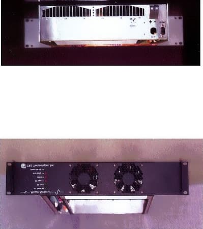
Click to zoom
Application Details
- Equipment Class
- AMP - Amplifier
- Date of Grant
- Aug 21, 2000
- Application Purpose
- Original Equipment
- Date of Application
- Feb 01, 2000
- Equipment Note
- Base Station
- Frequency Range
- 869.00000000 - 894.00000000
- Company
- TRL Technologies, Inc.
- Country
- United States
Documents & Files
Document Text
Text extracted from the exhibit documents filed with the FCC. Open a document above to read the original.
Users Manual
TRL TECHNOLOGIES, INC.FCC ID: OEUPA882M180WS2 PAGE 1 OF 2 POWER SERIES II 180W 869-894MHZ RF POWER AMPLIFIER USER MANUAL 1. GENERAL DESCRIPTION The Power Series II 180W, 869-894MHz Power Amplifier is a high power amplifier (PA) that incorporates LDMOS technology to provide high efficiency and rugged operation. It is developed for cellular application. The PA features various alarms and protection circuitry, Automatic Level Control (ALC) and cooling fans. 2. INSTALLATION Note: Make sure the PA’s output port is appropriately terminated before applying any RF input signal. Connect the RF input signal to the PA’s input port labeled RF IN. Connect the PA’s output port labeled RF OUT to a RF load or an antenna. Connect a DC power supply source to the terminal block labeled + -. Apply the required 26VDC @ 20A voltage. After going through an initialization state, the PA’s DC POWER LED (green) and RF INPUT LED (red) should be on. Apply and then slowly increase the RF input signal (20W max, 869-894MHZ). Monitor the RF output. Continue increasing the RF input level until 180W is reached at the RF output port. RF INPUT LED should turn off. TX ON LED (green) should turn on. The PA is now transmitting. No other adjustment is necessary. 3. SPECIFICATIONS Electrical Frequency Range:869-894 MHz Output Power:180 Watts (max) ALC Settling Time:100ms max to within ± 1dB of final value Input Power:20 Watts (max) Input Return Loss:-10.0 dB (max) Harmonics & Spurious:-70dBc (max) EMI:FCC Specifications Stability:Under 3:1 VSWR DC Supply Voltage:26-28 V Input DC Power:600 Watts (maximum) RF Load VSWR:Full power at better than 2:1 VSWR Fold Back Condition:Load 2:1-3:1 VSWR: fold back by 3dB (Po=90W) TRL TECHNOLOGIES, INC.FCC ID: OEUHPA460M250W PAGE 2 OF 2 Over temperature range: +50 to +60°C fold back by 3dB (Po=90W) DC supply voltage: below +26V full power until ALC=5V Shutdown condition: Input Power:Input power greater than 20 Watts Dump Load:Final pallet fails Over Temperature:Ambient temperature greater than +60°C Heat sink temperature greater than +90°C Load VSWR:Greater than 3:1 VSWR DC Supply Voltage:Less than 22V or greater than 30V RF Output Power Control:Output power is adjustable from 20 to 180W through front-panel mounted -10-turn pot Alarms and Indicators: DC PWR ON, Green LED:ON:between 25-28V Flash:between 22-25V or 28-30V OFF:less than 22V or greater than 30V TX ON, Green LED:ON, power amplifier is functional RF INPUT, Red LED:ON:No RF input power Flash:RF input is Over/Under specification High VSWR, Red LED:ON:greater than 2:1 VSWR Over Temp, Red LED:Flash: Ambient temp between +50 to +60°C ON: Ambient temp greater than +60°C ON:Heat sink temp greater than +90°C Connectors: RF in/out:N type-Female DC:Terminal block 9-pin DSUB femalePin #Connection 1Low Output Power/BYPASS (0V-no fault, 5V-fault) 2 Over Temperature (0V-no fault, 5V-fault) 3 Input Power (0V-no fault, 5V-fault) 4 NC (FORM_C Relay) 5 NO (FORM_C Relay) 6 GROUND (Ground) 7 VSWR (0V-no fault, 5V-fault) 8 External Reset 9 COMMON Environmental Operating Temp:-30 to 45°C Mechanical Cooling Fan:Internal fan, forced air front to rear
External Photos
TRL TECHNOLOGIES, INC.FCC ID: OEUPA882M180WS2 PAGE 1 OF 2 External, Front and Back, without Cover TRL TECHNOLOGIES, INC.FCC ID: OEUPA882M180WS2 PAGE 2 OF 2 External, Back, with Cover
ID Label/Location Info
TRL TECHNOLOGIES, INC. FCC ID: OEU882M180WS2 PAGE 1 OF 2 SERIAL NO: 2000 FCC ID: OEUPA882M180WS2MODEL NO.: A180032882B FREQUENCY: 869 - 894 MHz TRL TECHNOLOGIES, INC TRL TECHNOLOGIES, INC.FCC ID: OEU882M180WS2 PAGE 2 OF 2 .500 1.750 TRL TECHNOLOGIES, INC. FCC ID: OEUPA882M180WS2 SERIAL NO.: MODEL NO.: A180320882B FREQUENCY: 869-894 MHz
Internal Photos
TRL TECHNOLOGIES, INCFCC ID: OEUPA882M180WS2 PAGE 1 OF 2 Internal and Control Board TRL TECHNOLOGIES, INCFCC ID: OEUPA882M180WS2 PAGE 2 OF 2 Internal
Operational Description
TRL TECHNOLOGIES, INC.FCC ID: OEUPA882M180WS2 Page 1 of 4 OPERATIONAL DESCRIPTION 1. DESCRIPTION a) Individual Stages The Power Amplifier is divided into the following sections: • Splitter / Driver Stage: divides into DC and RF sections. DC section covers DC supply regulation, display LEDs. RF section includes attenuators, RF splitters, RF input detector circuit and driver amplification. • Amplification Stage: consists of two final amplifier pallets. • Combiner Stage: consists of power monitor circuitries, combiner, circulator and low pass filter. • PA Control: contains input signals, microprocessor and output signals sections. b) Overall Lineup The RF input is attenuated, split and routed to an input-power-detection circuit and a variable attenuator. The signal is further attenuated, amplified and passed to another splitter. The result is then fed to 2 final power amplifier pallets, combined and routed to a circulator and then a low pass filter before going out to the PA’s output port. There are sensors and couplers placed through out the PA to monitor the PA’s input level, forward and reflected power output levels, as well as the ambient and heat sink temperature. These sensor and coupler voltages are utilized by the on-board HC11 microprocessor to provide various PA alarm and protection. 2. FEATURES The 180W Power Series II PA provides numerous alarm monitor and protection features. a) Fold Back Mode The PA will go to the Fold Back Mode and reduce its power by 3dB (90W) when • Load VSWR is between 2:1 to 3:1 • Ambient temperature is between 45 to 60°C b) Alarm Indicators AlarmsLED StatusCondition DC PowerSolid Green LED Flashing Off Between 25V-28V Between 22-25V or 28V-30V Less than 22V or Greater than 30V or No power at all TX OnSolid Green LED Off PA is transmitting PA is not transmitting RF InputSolid Red LED Flashing Off No input power Over/Under limit specification Input power is within limit High VSWRSolid Red LED Off Greater than 2:1 VSWR No alarm Over TempSolid Red LED Flashing Off Ambient Temp is greater than 60°C or Heat sink Temp is greater than 90°C Ambient Temp is between 45 to 60°C No alarm Table 1. Alarms 3. ALARM CONNECTOR TRL TECHNOLOGIES, INC.FCC ID: OEUPA882M180WS2 Page 2 of 4 Pin #Signals 1Forward Power (0V-no fault, 5V-fault) 2Over temperature (0V-no fault, 5V-fault) 3Input Power (0V-no fault, 5V-fault) 4Relay (5V) 5Ground 6VSWR (0V-no fault, 5V-fault) 7External Reset 8Relay NC 9Relay COMMON 10Relay NO Table 2. DB9 Alarms Connector TRL TECHNOLOGIES, INC. FCC ID: OEUPA882M180WS2 Page 3 of 4 INPUT FROM DRIVERFORWARD_POWERREVERSE_POWERHS_TEMPAMBIENT_TEMP_VINPUT_PWR_DET_VDUMP_LOADPA_CONTROLREG_15V5VPS_VOLTAGEPS_VOLTAGEINPUT FROM FRONT PANELPWR OUT ADJUST OUTPUT TO FRONT PANEL LEDSDC PWRTX ONRF INPUTVSWROVER TEMPOUTPUT TO 9-PIN DB ON BACKHEAT SINK TEMPFWD PWRRELAY CONTROL SIGNALS5VDC FAN VOLTAGE FIGURE 1. PA CONTROL DIAGRAM PA CONTROL TRL TECHNOLOGIES, INC. FCC ID: OEUPA882M180WS2 Page 4 of 4 To Alarm LEDs To Alarm Connector To Control Board Control Board AMPs AMPs Attenuator Splitter Attenuators Combiner Splitter Circulator LPF RFIN RF OUT Driver / DC Board Combiner Board To Power In Detector FIGURE 2. PA BLOCK DIAGRAM
Parts List/Tune Up Info
TRL TECHNOLOGIES, INC. FCC ID: OEUPA882M180WS2 PCB Assembly, Driver/Splitter ItemQtyDescriptionMan. Part # Reference 11Temperature SensorLM50BU12 21Coupler, 90 Deg. HybridS03A888N1H1 31Coupler, 90 Deg. HybridSLC-090UH2 41Diode, DetectorHSM2800D1 51Attenuation, Variable, AV104-12U2 61RF GainRF2108U6 PCB Assembly, PTF10020 Pallet ItemQtyDescriptionMan. Part # Reference 11Ericsson LDMOS PTF10020, 125 WattPTF10020Q1 21REGULATOR, 15VLM78L15U1 PCB Assembly, Combiner ItemQtyDescriptionMan. Part # Reference 13Diode, DetectorHSMS2800D2, D3, D16 21Temp SensorLM35DTU1 PCB Assembly,Control/LED ItemQtyDescriptionMan. Part #Reference 1 3Diode, Dual Zener, 5.6VMMBZ5V6ALT1 D1,D2,D3 2 1IC, D/A ConvertorMAX534ACEE U2 3 1IC, HEX, Non-InvertorMC74HC241ADW U13 4 1IC, Micro-ProcessorMC68HC711E9CFN2 U1 5 1IC, Dual OP AMPMC33172D U5 6 2IC, Quad OP AMPMC33204D U3,U9 7 1IC, Serial InterfaceDS14C232CM U8 8 1IC, Unde-voltage SensenMC34164D-5 U6 9 1Precision Reference Voltage, 5VLM4040DAIM3-5.0D5 10 1XTAL, 8MHZ AS-8.000-18-SMD XTAL1 Page 1 of 1
Parts List/Tune Up Info
TRL TECHNOLOGIES, INC.FCC ID: OEUPA882M180WS2 PAGE 1 OF 1 TUNE UP PROCEDURE All necessary tuning is performed before the PA is shipped. The following power adjustment procedure is provided for reference or verification purpose: • Connect the PA’s input port to a RF source. • Connect the PA’s output port to a 50Ohm, 180W load. • Connect the PA’s DC input to a DC supply. Turn the supply on and Set for 26V @ 20A. • Adjust R48, power adjust pot, on the control board for 3V. • Apply a RF signal between 869-894MHZ and set it to the appropriate amplitude. • Adjust R3, input detector voltage pot, on the driver board. Set it for 1.5V. • Adjust R79, forward detector pot, on the combiner board for 180W at the output. Measure its resistance at the center pin. • Adjust R80, reverse detector pot, on the combiner board. Monitor its resistance at the center pin. Set it to the same resistance value as of R79.
Schematics
TRL TECHNOLOGIES, INC. FCC ID: OEUPA882M180WS2 PAGE 1 OF 5 TRL TECHNOLOGIES, INC. OEUPA882M180WS2 PAGE 2 of 5 TRL TECHNOLOGIES, INC. FCC ID: OEUPA882M180WS2 PAGE 3 of 5 TRL TECHNOLOGIES, INC. FCC ID: OEUPA880M180WS2 PAGE 4 of 5 TRL TECHNOLOGIES, INC. FCC ID: OEUPA882M180WS2 PAGE 5 of 5
Test Report
TRL TECHNOLOGIES, INC.FCC ID: OEUPA882M180WS2 TRL TECHNOLOGIES, INC.FCC ID: OEUPA882M180WS2 ENGINEERING TEST REPORT NO. 22443 ADMINISTRATIVE DATA AND SUMMARY OF TESTS DESCRIPTION OF TEST ITEM : 180 Watt Amplifier for single channel operation MODEL NO: A180320882B SERIAL NO: None Assigned FCC ID: OEUPA882M180WS2 MANUFACTURER: TRL Technologies, Inc. APPLICABLE SPECIFICATIONS: FCC Parts 2 and 22 QUANTITY OF ITEMS TESTED: One (1) TEST PERFORMED BY: ELITE ELECTRONIC ENGINEERING COMPANY Radio Interference Consultants Downers Grove, Illinois 60515 DATES TESTED: February 3, 2000 PERSONNEL (OPERATORS, OBSERVERS, AND CO-ORDINATORS): CUSTOMER: Hiep Lam of TRL Technologies was present for all testing. ELITE ELECTRONIC: Daniel E. Crowder ELITE JOB NO.: 28475 ABSTRACT: The Model No. A180320882B, 180 Watt Amplifier complies with the occupied bandwidth and spurious radiated emissions requirements in FCC PART 22. See test results and data pages for more details. TRL TECHNOLOGIES, INC.FCC ID: OEUPA882M180WS2 TRL TECHNOLOGIES, INC.FCC ID: OEUPA882M180WS2 ENGINEERING TEST REPORT NO. 22443 MEASUREMENT OF RF INTERFERENCE FROM A MODEL NO. A180320882B 180 WATT AMPLIFIER 1.0 INTRODUCTION: 1.1 DESCRIPTION OF TEST ITEM: This report present the results of the radio interference measurements were performed on a 180 Watt Amplifier for single channel cellular applications, Model No. A180320882B,(hereinafter referred to as the test item). No serial number was assigned to the test item. The tests were performed for TRL Technologies of Hoffman Estates, Illinois. 1.2 PURPOSE: The test series was performed to determine if the test item meets the occupied bandwidth and spurious radiated emissions requirements of the FCC Part 22 for 869-894MHz Amplifiers. 1.3 DEVIATIONS, ADDITIONS AND EXCLUSIONS: There were no deviations, additions to, or exclusions from the test specification during this test series. 1.4 APPLICABLE DOCUMENTS: The following documents of the exact issue designated form part of this document to the extent specified herein: Federal Communications commission "Code of Federal Regulations", Title 47, Part 22 Federal communications Commission "Code of Federal Regulations", Title 47, Part 2 ANSI C63.4-1992, "American National Standard for Methods of Measurement of Radio-Noise Emissions from Low-Voltage Electrical and Electronic Equipment in the Range of 9 kHz to 40 GHz" 1.5 SUBCONTRACTOR IDENTIFICATION: This series of tests was performed by the Elite Electronic Engineering Company, radio interference consultants of Downers Grove, Illinois. 1 TRL TECHNOLOGIES, INC.FCC ID: OEUPA882M180WS2 ENGINEERING TEST REPORT NO. 22443 2.0 TEST ITEM SETUP AND OPERATION: 2.1 SETUP: The test item was powered with 26VDC from a power supply. An input signal from a Hewlett Packard model 8648C signal generator (used in conjunction with a Hewlett Packard 8111A function generator) was fed into an Ophir model GRF5064 RF power amplifier. The 15 Watt output of the Ophir amplifier was used to drive the test item. The level of the input signal was adjusted until the power output was at the maximum level. 2.2 MODULATION: The test signal was frequency modulated (FM) with a 6.5 kHz audio tone at 12.0kHz deviation which is a typical modulation for 869-894MHz radio services. 2.3 FREQUENCY SELECTION: A single frequency in the center of the frequency band was selected. The specific test frequencies are designated as follows: Modulation Frequency Type (MHz)_____ FM 881.5 3.0 TEST EOUIPMENT: A list of the test equipment used can be found on Table 1. All equipment was calibrated per the instruction manuals supplied by the manufacturer. 4.0 REQUIREMENTS, PROCEDURES AND RESULTS: 4.1 OCCUPIED BANDWIDTH MEASUREMENTS: 4. 1. 1 REQUIREMENTS: In accordance with Paragraph 22.917(b), the peak power of any emission shall be attenuated below the 2 TRL TECHNOLOGIES, INC.FCC ID: OEUPA882M180WS2 ENGINEERING TEST REPORT NO. 22443 Unmodulated carrier power(P)in accordance with the following schedule: (1)On any frequency removed from the carrier frequency by more than 20kHz but not more than 45kHz: At least 26 dB. (2)On any frequency removed from the carrier frequency by more than 45kHz, up to the first multiple of the carrier frequency: at least 60dB or 43 + 10log (P) dB, whichever is the lesser attenuation. 4.1.2 PROCEDURES: (a) The input signal was set to 881.5MHz. The input signal level was adjusted to provide the maximum level at the test item output. (b) The input signal was FM modulated. (c) A spectrum analyzer was connected to the output of the test item. With a bandwidth of the spectrum analyzer set to 1kHz, the output of the test item was measured and recorded. (d) The input signal from the driving amplifier was measured with the spectrum analyzer and recorded over the same frequency range. 4.1.3 RESULTS: The plots of the occupied bandwidth measured with the FM modulation of the carrier are presented on data pages 101 through 105. The limits, shown on the plots, are referenced to the power measured from the unmodulated carrier. As can be seen from the data, the test item output met the occupied bandwidth requirements with the FM modulation of the carrier. The sideband emissions measured at the test item output were similar to the sideband emissions measured from the input signals. 4.2 FIELD STRENGTH OF SPURIOUS EMISSIONS: 4.2.1 REQUIREMENTS: In accordance with Paragraph 22.917, 3 TRL TECHNOLOGIES, INC.FCC ID: OEUPA882M180WS2 ENGINEERING TEST REPORT NO. 22443 on any frequency removed from the assigned frequency by more than 250 percent of the authorized bandwidth: by at least 43 + 10 log(P)dB. This requirement translates to a field strength limit of -13dBm (ERP). The emissions shall be measured from 3OMHz up to the 10th harmonic of the fundamental frequency. 4.2.2 PROCEDURES : The radiated tests were performed in a 32ft. x 20ft. x 18ft. hybrid ferrite-tile/anechoic absorber lined test chamber. With the exception of the floor, the reflective surfaces of the shield…
Text truncated - open the document above for the full version.
Test Report
TRL TECHNOLOGIES, INC.FCC ID: OEUPA882M180WS2 TRL TECHNOLOGIES, INC.FCC ID: OEUPA882M180WS2 TRL TECHNOLOGIES, INC.FCC ID: OEUPA882M180WS2 TRL TECHNOLOGIES, INC.FCC ID: OEUPA882M180WS2
Test Report
TRL TECHNOLOGIES, INC.FCC ID: OEUPA882M180WS2 TRL TECHNOLOGIES, INC.FCC ID: OEUPA882M180WS2 TRL TECHNOLOGIES, INC.FCC ID: OEUPA882M180WS2 TRL TECHNOLOGIES, INC.FCC ID: OEUPA882M180WS2
Test Report
TRL TECHNOLOGIES, INC . FCC ID: OEUPA882M180WS2 PAGE 1 OF 4 SIGNAL GENERATOR HP8648C DRIVER CIR ATTENUATOR SPECTRUM ANALYZER HP8561E DUT Occupied Bandwidth Measurement Test Setup The Signal generator supplies a low RF level that is amplified, by the driver, to a suitable input RF levelto the PA.The PA output is set to 180W.The RF signal is external modulated with output signal from the function generator FUNCTION GENERATOR HP8111A TRL TECHNOLOGIES, INC.FCC ID: OEUPA882M180WS2 PAGE 2 OF 4 1.0 TEST SETUP The PA’s frequency was set to 881.5MHz and FM modulated with a 3 kHz 50% duty cycle square wave at a 5kHz deviation. The output power was set to 180W. 2.0 RESULTS In accordance with paragraph 22.917 (d) the peak power of any emission shall be attenuated below the unmodulated carrier power (P) in accordance with the following: (1) On any frequency removed from the carrier frequency by more than 20kHz but not more than 45kHz: At least 26dB. (2) On any frequency removed from the carrier frequency by more than 45kHz but not more than 90kHz: At least 45dB. (3) On any frequency removed from the carrier frequency by more than 45kHz, up to the first multiple of the carrier frequency: at least 60dB or 43 + 10log(P)dB, whichever is the lesser attenuation. The occupied bandwidth measurement results were plotted in figure 1 and 2. The limits are referenced to the power measured from the unmodulated carrier. As can be seen from the data, the sideband emissions measured at the output were similar to the sideband emissions measured from the input. TRL TECHNOLOGIES, INC.FCC ID: OEUPA882M180WS2 PAGE 3 OF 4 Figure 1. Input Spectrum TRL TECHNOLOGIES, INC.FCC ID: OEUPA882M180WS2 PAGE 4 OF 4 Figure 2. Output Spectrum
Test Report
TRL TECHNOLOGIES, INC . FCC ID: OEUPA882M180WS2 PAGE 1 OF 4 SIGNAL GENERATOR HP8648C DRIVER CIR ATTENUATOR SPECTRUM ANALYZER HP8562E DUT Conducted Spurious Measurement Test Setup The Signal generator supplies a low RF level that is amplified, by the driver, to a suitable input RF level to the PA.The PA output is set to 180W.The attenuation level is 60dB.The conducted spurious emissions were measured up to 10 th harmonic. TRL TECHNOLOGIES, INC.FCC ID: OEUPA882M180WS2 PAGE 2 OF 4 TRL TECHNOLOGIES, INC.FCC ID: OEUPA882M180WS2 PAGE 3 OF 4 TRL TECHNOLOGIES, INC.FCC ID: OEUPA882M180WS2 PAGE 4 OF 4
Test Report
TRL TECHNOLOGIES, INC.FCC ID: OEUPA882M180WS2 This is to reply to your email correspondence reference number 14801, 731 reference number EA96680, FCC ID OEUPA882M180WS2 1. We are requesting that the spurious, radiated, conducted and occupied bandwidth tests at 20W input to be waived due to the fact that the PA is designed so that the input RF level to the driver gain stage always remains constant. In other words, the PA’s overall RF characteristic will not change with the input level’s variation. As show in block diagram below, the variable RF signal at the PA input is always padded down to a fixed level before feeding to AMP1. This is done using a combination of resistive attenuator (1), voltage variable attenuator (2) and resistive network attenuator (3). The resistive attenuator (1) is varied from 5, 10, 15 or 20dB depending on the customer’s input level. The voltage variable attenuator (2), which controlled by the microprocessor, is then used to fine tune the RF signal to a fixed level expected at AMP1 input. The result is the same RF signal will be passing through the entire gain lineup every time, independence of the PA input. 2. A copy of the occupied bandwidth with digital input file is uploaded as Test Report: occupied bandwidth data. Note that the same copy was also uploaded earlier under Add Attachment as part of the submitted data. 3. Intermodulation test is not required for the PA since it is operated as a single channel system. TRL TECHNOLOGIES, INC. FCC ID: OEUPA882M180WS2 To Alarm LEDs To Alarm Connector To Control Board Control Board AMPs AMPs Attenuator Splitter Attenuators Combiner Splitter Circulator LPF RFIN RF OUT Driver / DC Board Combiner Board T o P ow e r In D etecto r PA BLOCK DIAGRAM 1 2 3 1 Fixed Input
Test Report
TRL TECHNOLOGIES, INC . FCC ID: OEUPA882M180WS2 PAGE 1 OF 4 SIGNAL GENERATOR HP8648C DRIVER CIR ATTENUATOR SPECTRUM ANALYZER HP8561E DUT Occupied Bandwidth Measurement Test Setup The Signal generator supplies a low RF level that is amplified, by the driver, to a suitable input RF level to the PA. The PA output is set to 180W. The RF signal is external modulated with output signal from the function generator FUNCTION GENERATOR HP 8 111A TRL TECHNOLOGIES, INC . FCC ID: OEUPA882M180WS2 Page 2 of 4 1.0 TEST SETUP The PA’s frequency was set to 881.5MHz and FM modulated with a 3 kHz 50% duty cycle square wave at a 5kHz deviation. The output power was set to 180W. 2.0 RESULTS In accordance with paragraph 22.917 (d) the peak power of any emission shall be attenuated below the unmodulated carrier power (P) in accordance with the following: (1) On any frequency removed from the carrier frequency by more than 20kHz but not more than 45kHz: At least 26dB. (2) On any frequency removed from the carrier frequency by more than 45kHz but not more than 90kHz: At least 45dB. (3) On any frequency removed from the carrier frequency by more than 45kHz, up to the first multiple of the carrier frequency: at least 60dB or 43 + 10log(P)dB, whichever is the lesser attenuation. The occupied bandwidth measurement results were plotted in figure 1 and 2. The limits are referenced to the power measured from the unmodulated carrier. As can be seen from the data, the sideband emissions measured at the output were similar to the sideband emissions measured from the input. TRL TECHNOLOGIES, INC FCC ID: OEUPA882M180WS2 PAGE 3 OF 4 Figure 1. Input Spectrum TRL TECHNOLOGIES, INC FCC ID: OEUPA882M180WS2 PAGE 4 OF 4 Figure 2. Output Spectrum
Contact Information
Applicant
Hiep Lam(Electrical Engineer)
Test Firm
Elite Electronic Engineering Co.Daniel Crowder
Technical Specifications
| # | Rule Parts | Frequency Range | Power Output | Emission |
|---|---|---|---|---|
| 4 | 22 | 869 MHz - 894 MHz | 180 W | F3E |
Other Applications from TRL Technologies, Inc.

OEUB8001900-1C
Jul 05, 2005Wireless In-Vehicle Cellular Signal Enhancer
Equipment Class
AMP - Amplifier
OEUB851-1A
Jun 09, 2005iDEN Wireless Compensator
Equipment Class
AMP - Amplifier
OEUBDA1900-2
Oct 24, 2004In-Home Cellular Signal Enhancer
Equipment Class
PCB - PCS Licensed Transmitter
OEUB8001900-1A
Sep 21, 2004Wireless In-Vehicle Cellular Signal Enhancer
Equipment Class
PCB - PCS Licensed Transmitter
OEUB8001900-1
Aug 15, 2004Wireless In-Vehicle Cellular Signal Enhancer
Equipment Class
PCB - PCS Licensed Transmitter