OEUPA936M125W
TRL Technologies, Inc.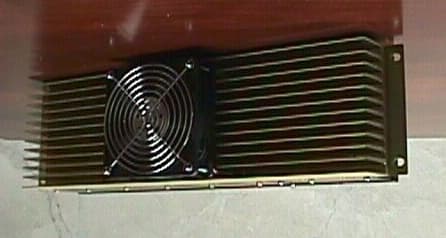
Click to zoom
Application Details
- Equipment Class
- AMP - Amplifier
- Date of Grant
- Aug 09, 1999
- Application Purpose
- Original Equipment
- Date of Application
- May 13, 1999
- Frequency Range
- 928.00000000 - 944.00000000
- Company
- TRL Technologies, Inc.
- Country
- United States
Documents & Files
Document Text
Text extracted from the exhibit documents filed with the FCC. Open a document above to read the original.
Users Manual
TRL TECHNOLOGIES, INC.FCC ID: OEUPA936M125W PAGE 1 OF 2 RF IN RF OUT 125W 928-944MHZ RF POWER AMPLIFIER MODEL # A125310960B USER MANUAL 1. GENERAL DESCRIPTION The 125W 928-944MHz Power Amplifier incorporates LDMOS technology to provide high efficiency and rugged operation. The PA features a compact housing, alarm display LEDs and cooling fan. 2. INSTALLATION Note: DO NOT operate the PA unless all RF connections are secured and properly terminated. Figure 1. Front Display and Connections The PA’s power out is set in the factory for 125W at a selected customer frequency. There is no adjustment required. The following procedure is for reference purpose only. • Connect the PA’s RF IN port to a RF source. • Properly terminate the PA’s RF OUT port with a 125W 50Ohm load. • Connect a DC power supply source to the terminal block labeled + -. • Turn on the DC power supply and set for 26V @ 18A. The PA’s DC POWER LED and cooling fan should be on. • Set RF source’s frequency within the range of 928 to 944 MHz. Turn on the RF signal. Adjust the RF input level for 125W at the output port. The input RF level should remain below or equal to 20dBm. 3. SPECIFICATIONS Model #A125310936B - + DC POWER TEMP VSWR FUSE TRL TECHNOLOGIES, INC.FCC ID: OEUPA936M125W PAGE 2 OF 2 FCC ID OEUPA936M125W Electrical Frequency Range928-944 MHz Output Power125 Watts ALC Settling Time100ms max to within ± 1dB of final value Input Power20 dBm max Input Return Loss-10 dB Harmonics & SpuriousAt least -70dBc StabilityLess than 3:1 VSWR DC Supply Voltage26 V ± 0.5 V Input DC Power468 Watts RF Load VSWRFull power at better than 2:1 VSWR Environmental Operating Temp:-30 to 45 ° C Humidity:0-95% relative humidity, no condensing Operating Altitude0-12,000 feet Mechanical CoolingSingle external fan, forced air along the sides
External Photos
TRL TECHNOLOGIES, INC.FCC ID: OEUPA936M125W PAGE 1 OF 1 FRONT BACK
ID Label/Location Info
TRL TECHNOLOGIES, INC.FCC ID: OEU PA936M125W PAGE 1 OF 1 S ER IAL NO : 2000 O U TP U T P O W E R : 125 W ATTS FR EQ UENC Y: 928-944 M Hz M O DEL NO .: A125310936B FC C ID: O EU PA936M 125W DC POW ER TE M P VS W R + _ RF INPUT RF OUTPUT FC C ID : O E U PA9 36M 1 25W M O D E L N O .: A1 25 3109 36B FR E Q U E N C Y: 92 8-944 M H z O U TP U T P O W E R : 12 5 W ATTS S E R IAL N O : 20 00
Internal Photos
TRL TECHNOLOGIES, INC.FCC ID: OEUPA936M125W PAGE 1 OF 2 PA UNIT DC / SPLITTER / TEMP MONITOR TRL TECHNOLOGIES, INC.FCC ID: OEUPA936M125W PAGE 2 OF 2 FINAL PA MODULES COMBINER / CIRCULATOR / LP FILTER
Operational Description
TRL TECHNOLOGIES, INC.FCC ID: OEUPA936M125W PAGE 1 OF 2 OPERATIONAL DESCRIPTION 1. DESCRIPTION a) Individual Stages The Power Amplifier is divided into the following sections: • Splitter Stage: includes DC supply, display LEDs, driver, temperature sensor and 2-way hybrid splitter. • Amplification Stage: consists of two 100W final amplifier modules. • Combiner Stage: consists of VSWR monitor circuitry, hybrid combiner, circulator and low pass filter. b) Overall Lineup The input RF is padded down and fed to a MMIC gain block before getting amplified by a RF power transistor that has adjustable gain. This intermediate amplified RF signal goes through a 2-way hybrid splitter and then amplified again by 2 final PA modules. The resultant signals are recombined and routed to a circulator and then a low pass filter before going out to the PA’s output port. A temperature sensor locating on the driver board monitors the PA’s heat sink temperature. Temp LED display will turn on when the heat sink temperature is exceeded 65°C. The PA’s Output VSWR level is monitored at the circulator load. VSWR LED display will turn on when the output VSWR is approximately 3:1. SignalsLEDCondition DC PowerGreenDC power is on VSWRRedGreater or equal to 3:1 VSWR at the output TempRed Ambient Temp is at least 65°C Table 1. LED Display TRL TECHNOLOGIES, INC. FCC ID: OEUPA936M125W PAGE 2 OF 2 V_ DUMP LOAD V_FWDV_RFL FINAL TEMP SENSOR LPF V_ DUMP LOAD AMP1 COMBINER LED DISPLAYDC POWERTEMPVSWR RF IN RF OUT AMP AMP4 ATTENUATOR DRIVER SPLITTER TEMP VSWR AMP1 RF OUT CIRCULATOR
Parts List/Tune Up Info
TRL TECHNOLOGIES, INCFCC ID:OEUPA936M125W 125 W,928-944MHZ, POWER AMPLIFIER Splitter ItemDescriptionReferencePart # 1Hybrid QuadratureH1S03888N1 2Transistor, NPNQ1-2MMBT3904LT1 3Regulator, 5VDCU1MC78T05CT 4Regulator, 15VDCU2MC78T15CT 5OPAMPU3MC33172D 6Temp SensorU4LM35DM 8MMICU5SNA-586 9RF MODULE, 16WU6MHW916 Final Amplifier Module ItemDescriptionReferencePart # 1LDMOS RF Power TransistorQ1XRF187S 2Regulator, Fixed, 15V U1LM78L15A Combiner/Circ/LowPassFilter ItemDescriptionReferencePart # 1Circulator 925-960MHz 125WFIL1DDF1211 2Hybrid QuadratureH1RFP-915-90-400-201 3Diode, SchottkyD2HSMS2800 Page 1 of 1
Parts List/Tune Up Info
TRL TECHNOLOGIES, INC.FCC ID: OEUPA936M125W PAGE 1 OF 1 TUNE UP PROCEDURE This tuning procedure is for reference purpose only. The PA is set in the factory to 125W at a determine customer frequency. There is no adjustment needed. 1. Equipments • Directional coupler • RF load • DC power supply • Power meter 2. Tuning Procedure • Connect the PA’s input port to a RF source. • Terminate the PA’s output port with a 50Ohm, 125W load. • Connect the PA’s DC input to a DC voltage source (capable of supply up to 18A @ 26V). • Turn on the DC supply and set for 26VDC @ 18A. • Apply a RF signal to the input port at a level that will produce 125W at the output port. The input level should be less than or equal to 20dBm. DC SUPPLY RF SOURCE LOAD COUPLER POWER METER PA COUPLER COUPLER POWER METER
Schematics
TRL TECHNOLOGIES, INC. FCC ID: OEUPA936M125W PAGE 1 OF 4 TRL TECHNOLOGIES, INC. FCC ID: OEUPA936M125W PAGE 2 OF 4 TRL TECHNOLOGIES, INC. FCC ID: OEUPA936M125W PAGE 3 OF 4 TRL TECHNOLOGIES, INC. FCC ID: OEUPA936M125W PAGE 4 OF 4
Test Report
ENGINEERING TEST REPORT NO. 21661 ADMINISTRATIVE DATA AND SUMMARY OF TESTS DESCRIPTION OF TEST ITEM: 125 Watt Amplifier for single channel operation MODEL NO: A125310936B SERIAL NO: N/A FCC ID: OEUHPA460M250W MANUFACTURER: TRL Technologies APPLICABLE SPECIFICATIONS: FCC Parts 2 and 90 QUANTITY OF ITEMS TESTED: One (1) TEST PERFORMED BY: ELITE ELECTRONIC ENGINEERING COMPANY Radio Interference Consultants Downers Grove, Illinois 60515 DATES TESTED: May 3, 1999 PERSONNEL (OPERATORS, OBSERVERS, AND CO-ORDINATORS): CUSTOMER: Hiep Lam and Ken Cao of TRL Technologies personnel were present for all testing. ELITE ELECTRONIC: Daniel E. Crowder ELITE JOB NO.: 27694 ABSTRACT: The Model No. A125310936B, 125 Watt Amplifier complies with the occupied bandwidth and spurious radiated emissions requirements in FCC PART 90. See test results and data pages for more details. ENGINEERING TEST REPORT NO. 21661 TABLE OF CONTENTS PARAGRAPH DESCRIPTION OF CONTENTS PAGE NO. 1.0 INTRODUCTION1 1.1 DESCRIPTION OF TEST ITEM1 1.2 PURPOSE1 1.3 DEVIATIONS, ADDITIONS AND EXCLUSIONS1 1.4 APPLICABLE DOCUMENTS1 1.5 SUBCONTRACTOR IDENTIFICATION1 2.0 TEST ITEM SETUP AND OPERATION2 2.1 SETUP2 2.2 MODULATION2 2.3 FREQUENCY SELECTION2 3.0 TEST EQUIPMENT2 4.0 REQUIREMENTS, PROCEDURES AND RESULTS2 4.1 OCCUPIED BANDWIDTH MEASUREMENTS2 4.1.1 REQUIREMENTS2 4.1.2 PROCEDURES3 4.1.3 RESULTS3 4.2 FIELD STRENGTH OF SPURIOUS EMISSIONS4 4.2 1 REQUIREMENTS4 4.2.2 PROCEDURES4 4.2.3 RESULTS 4.3 SPURIOUS EMISSIONS AT ANTENNA TERMINALS 6 4.3.1 REQUIREMENTS 6 4.3.2 PROCEDURES 6 4.3.3 RESULTS 6 5.0 CONCLUSION7 6.0 CERTIFICATION7 TABLE I - EQUIPMENT LIST8 ENGINEERING TEST REPORT NO. 21661 1 MEASUREMENT OF RF INTERFERENCE FROM A MODEL NO. A125310936B 125 WATT AMPLIFIER 1.0 INTRODUCTION: 1.1 DESCRIPTION OF TEST ITEM: This report present the results of the radio interference measurements were performed on a 125 Watt Amplifier for single channel paging applications, Model No. A125310936B, Serial No. N/A, (hereinafter referred to as the test item). The tests were performed for TRL Technologies of Hoffman Estates, Illinois. 1.2 PURPOSE: The test series was performed to determine if the test item meets the occupied bandwidth, spurious emissions at antenna terminals and spurious radiated emissions requirements of the FCC Part 90 for 928-944MHz Amplifiers. 1.3 DEVIATIONS, ADDITIONS AND EXCLUSIONS: There were no deviations, additions to, or exclusions from the test specification during this test series. 1.4 APPLICABLE DOCUMENTS: The following documents of the exact issue designated form part of this document to the extent specified herein: -Federal Communications Commission "Code of Federal Regulations", Title 47, Part 90 - Federal Communications Commission "Code of Federal Regulations", Title 47, Part 2 - ANSI C63.4-1992, "American National Standard for Methods of Measurement of Radio- Noise Emissions from Low-Voltage Electrical and Electronic Equipment in the Range of 9 kHz to 40 GHz" 1.5 SUBCONTRACTOR IDENTIFICATION: This series of tests was performed by the Elite Electronic Engineering Company, radio interference consultants of Downers Grove, Illinois. 2.0 TEST ITEM SETUP AND OPERATION: 2.1 SETUP: The test item was powered with 26VDC from a power supply. ENGINEERING TEST REPORT NO. 21661 2 An input signal from a Hewlett Packard model 8648C signal generator (used in conjunction with a Hewlett Packard 8111A function generator) was fed into a Ophir model GRF5064 RF power amplifier. The 35 Watt output of the Ophir amplifier was used to drive the test item. The level of the input signal was adjusted until the power output was at the maximum level. 2.2 MODULATION: The test signal was frequency modulated (FM) with a 3.5 kHz audio tone at 14.0kHz deviation which is a typical modulation for 928-944MHz radio services. 2.3 FREQUENCY SELECTION: A single frequency in the center of the frequency band was selected. The specific test frequencies are designated as follows: ModulationFrequency Type (MHz) FM936.0 3.0 TEST EQUIPMENT: A list of the test equipment used can be found on Table I. All equipment was calibrated per the instruction manuals supplied by the manufacturer. 4.0 REQUIREMENTS, PROCEDURES AND RESULTS: 4.1 OCCUPIED BANDWIDTH MEASUREMENTS: 4.1.1 REQUIREMENTS: In accordance with Paragraph 90.209(b)(5), the maximum authorized bandwidth shall be 20kHz for operations in the bands 902MHz to 928MHz. In accordance with paragraph 90.210(b), the peak power of any emission shall be attenuated below the unmodulated carrier power (P) in accordance with the following schedule: (1)On any frequency removed from the assigned frequency by more than 50 percent but not more than 100 percent of the authorized bandwidth: At least 25 dB. ENGINEERING TEST REPORT NO. 21661 3 (2)On any frequency removed from the assigned frequency by more than 100 percent but not more than 250 percent of the authorized bandwidth: At least 35 dB. (3)On any frequency removed from the assigned frequency by more than 250 percent: At least 43 + 10log (P) dB. 4.1.2 PROCEDURES: (a)The input signal was set to 936.0MHz. The input signal level was adjusted to provide the maximum level at the test item output. (b)The input signal was FM modulated. (c)A spectrum analyzer was connected to the output of the test item. With a bandwidth of the spectrum analyzer set to 1kHz, the output of the test item was measured and recorded. (d)The input signal from the signal generator was measured with the spectrum analyzer and recorded over the same frequency range. 4.1.3 RESULTS: The plots of the occupied bandwidth measured with the FM modulation of the carrier are presented on data pages 101 through 103. The limits, shown on the plots, are referenced to the power measured from the unmodulated carrier. As can be seen from the data, the test item output met the occupied bandwidth requirements with the FM modulation of the carrier. The sideband emissions measured at the test item output were similar to the sideband emissions me…
Text truncated - open the document above for the full version.
Test Report
TRL TECHNOLOGIES, INC.FCC ID: OEUPA936M125W Page 1 of 7 OCCUPIED BANDWIDTH COMPARISION WITH A DIGITAL SIGNAL 1. TEST SETUP The PA’s frequency was set to 936MHz and FM modulated with a 3 kHz 50% duty cycle square wave at a 5kHz deviation. The output power was set to 125W. 2. RESULTS Occupied bandwidth was measured at the input and output of the PA with reference to the unmodulated carrier. As can be seen from figure 1 and 2, the input and output occupied bandwidth is identical. TRL TECHNOLOGIES, INC.FCC ID: OEUPA936M125W Page 2 of 7 ANTENNA TERMINAL SPURIOUS EMISSIONS 1. TEST SETUP The PA’s frequency was set to 936MHz and FM modulated with a 3 kHz 50% duty cycle square wave at a 5kHz deviation. The output power was set to 125W. 2. RESULTS In accordance with paragraph 90.209 (b), the mean power of emissions must be attenuated below the mean power of the unmodulated carrier (P) on any frequency removed from the assigned frequency by more than 250% of the authorized bandwidth: At least 43 + 10log(P) or –13dBm The antenna terminal spurious emissions were measured up to 10 th harmonic and plotted in figure 3, 4 and 5. TRL TECHNOLOGIES, INC.FCC ID: OEUPA936M125W Page 3 of 7 Figure 1 . Occupied Bandwidth, Input TRL TECHNOLOGIES, INC.FCC ID: OEUPA936M125W Page 4 of 7 Figure 2. Occupied Bandwidth, Output TRL TECHNOLOGIES, INC.FCC ID: OEUPA936M125W Page 5 of 7 Figure 4. Antenna Terminal Spurious Emissions, 30-1000 MHz -13 dBm TRL TECHNOLOGIES, INC.FCC ID: OEUPA936M125W Page 6 of 7 Figure 4. Antenna Terminal Spurious Emissions, 1000-2000 MHz -13 dBm TRL TECHNOLOGIES, INC.FCC ID: OEUPA936M125W Page 7 of 7 Figure. 5 Antenna Terminal Spurious Emissions, 2000-10000 MHz -13 dBm
Contact Information
Applicant
Hiep Lam(Electrical Engineer)
Test Firm
Elite Electronic Engineering Co.Daniel Crowder
Technical Specifications
| # | Rule Parts | Frequency Range | Power Output | Emission |
|---|---|---|---|---|
| 4 | 9 | 928 MHz - 944 MHz | 125 W | F3E |
Other Applications from TRL Technologies, Inc.

OEUB8001900-1C
Jul 05, 2005Wireless In-Vehicle Cellular Signal Enhancer
Equipment Class
AMP - Amplifier
OEUB851-1A
Jun 09, 2005iDEN Wireless Compensator
Equipment Class
AMP - Amplifier
OEUBDA1900-2
Oct 24, 2004In-Home Cellular Signal Enhancer
Equipment Class
PCB - PCS Licensed Transmitter
OEUB8001900-1A
Sep 21, 2004Wireless In-Vehicle Cellular Signal Enhancer
Equipment Class
PCB - PCS Licensed Transmitter
OEUB8001900-1
Aug 15, 2004Wireless In-Vehicle Cellular Signal Enhancer
Equipment Class
PCB - PCS Licensed Transmitter