OF8-AXO21Medical telemetry transmitter
Life Sensing Instruments, Inc.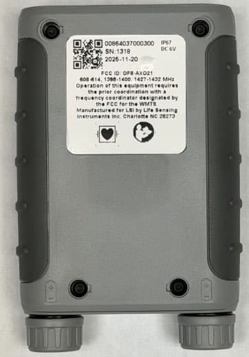
Click to zoom
Application Details
- Equipment Class
- TNB - Licensed Non-Broadcast Station Transmitter
- Date of Grant
- Aug 31, 2026
- Application Purpose
- Original Equipment
- Equipment Note
- Medical telemetry transmitter
- Frequency Range
- 603.30000000 - 613.70000000
- Country
- United States
Documents & Files
Document Text
Text extracted from the exhibit documents filed with the FCC. Open a document above to read the original.
Users Manual
Life Sensing Instruments, Inc. | CONFIDENTIAL pg. 1 AxisO 2 Transmitter Setup and Assembly Instructions Life Sensing Instruments, Inc. Life Sensing Instruments, Inc. | CONFIDENTIAL pg. 2 AxisO 2 Transmitter: Overview The AxisO 2 Transmitter is a component of a wireless medical patient-monitoring system designed to acquire and transmit electrocardiogram (ECG) physiological and pulse oximetry (SpO2) data to a telemetry receiver via a set of internal antennas. The AxisO 2 Transmitter is internally powered by (4) AAA batteries. AxisO 2 Transmitter: Setup & Assembly Instructions Insert the Batteries Unscrew each battery cap by grasping the battery cap and turning it counterclockwise until the cap has been full removed. Insert (2) AAA batteries into each battery well following the battery direction indicator on the back of the transmitter. Repeat the above instructions for the battery caps but rotate the battery cap clockwise to tighten. Power on the Transmitter Press and hold the button for (2) seconds to power on or off the transmitter. The transmitter will make an audible beep to indicate the transmitter is powering on or off. The Power Button’s LED will flash Purple to indicate the transmitter has a communication link with the Nexus Telemetry Receiver. Power down the Transmitter Press and hold the button for (2) seconds to power on or off the transmitter. System Disassembly Instructions • Power down the transmitter. • Remove the (4) batteries following the instructions above. • Rotate the battery caps clockwise to tighten. Life Sensing Instruments, Inc. | CONFIDENTIAL pg. 3 AxisO 2 Transmitter: Disassembly Instructions (Unit) 1. Power down the unit by removing the batteries. 2. Remove the four screws on the back of the AxisO 2 Transmitter housing using a Torx bit. 3. Gently lift the housing cover. Be careful not to tear the antennas that are glued to the cover. 4. Gently disconnect both antennas using a plastic pry tool. 5. Disconnect the ECG flex by lifting the latch on the CN2 connector and gently sliding the flex upward. 6. Disconnect the keypad pigtail by lifting the latch on the CN3 connector and gently sliding the flex downward. 7. Desolder the four wires attached to the PCB. 8. Remove the four screws securing the PCB. 9. Gently lift the PCB from the top side. 10. Disconnect the LCD on the rear of the PCB by lifting the latch. 11. Once the board is free, remove it from the housing.
Users Manual
Life Sensing Instruments, Inc. | CONFIDENTIAL Pg. 1 AXISO 2 TRANSMITTER Operator’s Manual Life Sensing Instruments, Inc. December 16, 2025 Life Sensing Instruments, Inc. | CONFIDENTIAL Pg. 2 AxisO 2 Transmitter Overview The AxisO 2 Transmitter is a component of a wireless medical patient-monitoring system designed to acquire and transmit electrocardiogram (ECG) and pulse oximetry (SpO 2 ) data to a telemetry receiver. The receiver forwards the data to a central monitoring station for display, trending, and analysis by healthcare professionals. The AxisO 2 uses four patient lead wires connected to disposable ECG electrodes to derive three ECG channels. The analog ECG signals are digitized, processed, and transmitted wirelessly using the Wireless Medical Telemetry Service (WMTS) frequency bands. In addition to ECG, the AxisO 2 supports pulse oximetry monitoring through an external Nonin XPOD module. The XPOD collects photoplethysmography (PPG) data via a compatible Nonin sensor and communicates the calculated SpO₂ and pulse rate values digitally to the AxisO 2 . AxisO 2 Keypad/Buttons The keypad provides a protective cover for the LCD, contains the assigned TrensCenter Channel Number, and has (4) buttons: • POWER BUTTON: o This button has a dual functionality – the button is used for powering the transmitter and displays high-level status information. o Power Functionality: Press and hold the button for (2) seconds to power on or off the transmitter. The transmitter will make an audible beep to indicate the transmitter is powering on or off. o Status Functionality: When the PMT is powered on, the Power Button will be illuminated with different colors to indicate the transmitter’s status: Orange: Transmitter is powered on without an active communication link with the Nexus Telemetry Receiver. To resolve, ensure that the transmitter is in the pre-defined wireless range and confirm that the Nexus Telemetry Receiver is powered on. Purple: Transmitter is powered on with an active communication link with the Nexus Telemetry Receiver. Blue: Transmitter is powered on with an active communication link with the Nexus Telemetry Receiver, and the transmitter has been admitted to TrensCenter software. Red: Transmitter has reached a state of low battery. Replace batteries to resolve. o Main Screen Functionality: Press this button to navigate to the Main Screen. Note: The Main Screen only displays when the Transmitter is admitted to TrensCenter. • VIEW BUTTON: o Lead Off Functionality: Press this button to navigate to the View Screen which displays the connection status of each ECG electrode. A Green Checkmark indicates that the electrode is connected. A Red X indicates that the electrode is disconnected. Note: This button only has functionality when the transmitter is admitted to TrensCenter. • STATUS BUTTON: o This button is used to access the Status Screen for support purposes. • REMOTE RECORD BUTTON: o Press and hold this button for (1) second to store a “Remote” Event in TrensCenter. Note: This button only has functionality when the transmitter is admitted to TrensCenter. AxisO 2 Display Overview The display has three modes of operation that are designed to maximize battery life. • Active Mode: The LCD is turned on and at full brightness. This mode is initiated when the keypad buttons are pressed, or the transmitter is powered on. Active Mode uses the most current and impacts battery life. • Inactive Mode: The LCD is turned on but has dimmed the brightness level due to inactivity. • Sleep Mode: The LCD is turned off due to inactivity. Sleep Mode uses the least amount of current and increases battery life. The display is configured to display Status Indicators at the top of all screens. Examples of Status Indicators include Channel Number, Filter/Monitor, Pacer, Remote Record, Primary/Auxiliary, Battery Strength, and Signal Strength. Life Sensing Instruments, Inc. | CONFIDENTIAL Pg. 3 The Main Screen displays the patient’s Heart Rate, SpO 2 %, and Pulse Rate (as determined and reported by TrensCenter) and the patient’s configured Target Heart Rate Range. Instructions for Use Insert the Batteries Unscrew each battery cap by grasping the battery cap and turning it counterclockwise until the cap has been full removed. Insert (2) AAA batteries into each battery well following the battery direction indicator on the back of the transmitter. Repeat the above instructions for the battery caps but rotate the battery cap clockwise to tighten. CAUTION: MAKE SURE THE BATTERIES ARE INSTALLED CORRECTLY. IF THE BATTERIES ARE INSTALLED INCORRECTLY, THE TRANSMITTER WILL NOT FUNCTION. CAUTION: MAKE SURE THAT THE BATTERY CAP IS TIGHT. IF THE CAP IS NOT TIGHTENED PROPERLY, THE TRANSMITTER SIGNAL MAY BE INTERMITTENT, AND THE WATERPROOFING SEAL MAY NOT SEAL WHICH MAY DAMAGE TO THE TRANSMITTER. Power on the Transmitter Press and hold the button for (2) seconds to power on or off the transmitter. The transmitter will make an audible beep to indicate the transmitter is powering on or off. The Power Button’s LED will flash Purple to indicate the transmitter has a communication link with the Nexus Telemetry Receiver. Connect the Lead Wires & Electrodes The patient lead wires have a color-coded connector that plugs into a corresponding color-coded transmitter connector. When inserting the lead wires, insert the connector until the cables fit firmly into the transmitter. CAUTION: ONLY USE THE LEAD WIRES SUPPLIED BY LSI FOR OPTIMAL PERFORMANCE. Gently abrade the electrode sites with an alcohol prep pad until slight redness is observed. Dry the site before applying the electrodes. Attach the electrodes to the patient on the prepared sites. Apply pressure to the outer edges of the electrode, not the center. Applying pressure to the center may cause the electrode conductive jelly to ooze out, resulting in a loose electrode. Attach the electrodes to the lead wires. For optimum monitoring, the electrodes should be placed in th…
Text truncated - open the document above for the full version.
External Photos
Life Sensing Instruments, Inc. | CONFIDENTIAL AxisO 2 Transmitter: External Photos Front: Back: Top: Bottom:
ID Label/Location Info
Life Sensing Instruments, Inc. | CONFIDENTIAL AxisO 2 Transmitter: FCC Label Label Size: 1.5” H x 1.5” W Life Sensing Instruments, Inc. | CONFIDENTIAL AxisO 2 Transmitter: FCC Label Location Label is applied on rear of housing
Internal Photos
Life Sensing Instruments, Inc. | CONFIDENTIAL AxisO 2 Transmitter: Internal Photos Life Sensing Instruments, Inc. | CONFIDENTIAL
RF Exposure Info
REVISED RADIO FREQUENCY EXPOSURE REPORT TO 111600-15 FOR THE AxisO2 Transmitter Report No.: 111600-15A Date of issue: May 8, 2026 PREPARED FOR: Alejandro Melchor Life Sensing Instruments, Inc. 2102 Cambridge Beltway Drive, Suite A1 Charlotte NC, 28273 PREPARED BY: S. Yamamoto CKC Laboratories, Inc. 5046 Sierra Pines Drive Mariposa, CA 95338 The test data contained in this report documents the observed testing parameters pertaining to and are relevant for only the sample equipment tested in the agreed upon operational mode(s) and configuration(s) as identified herein. Compliance assessment remains the client’s responsibility. This report may not be used to claim product endorsement by A2LA or any government agencies. This test report has been authorized for release under quality control from CKC Laboratories, Inc. Steve Behm Director of Quality Assurance & Engineering Services CKC Laboratories, Inc. Page 2 of 13 Report No: 111600-15A Purpose: To demonstrate compliance with United States, Canada, Australia, New Zealand, European Union and/or United Kingdom RF Exposure requirements for Portable equipment (devices used ≤20cm from the body) with power output below exemption levels or Mobile equipment (devices used >20cm from the body) where Maximum Permissible Exposure (MPE) Calculations apply. Device and Antenna Operating Configuration: Device operating at maximum output power with continuous transmission of modulated data. Method: This equipment is evaluated in accordance with the guidelines set forth in 47 CFR 1.1310, KDB 447498 & ANSI C95.1 for the US, Health Canada Safety Code 6 & RSS 102 for Canada, ARPANSA RPS S-1 for AU & NZ and EN 62479 or EN 62311 for EU and UK. Other Considerations: Report considers stand-alone equipment configurations only. RF Exposure limits are calculated at the mid-point of each operating band. The Device does NOT transmit simultaneously. Referenced Test Reports: The following test reports were referenced in conjunction with this assessment: 111600-7 Decision Rule: Outcome of RF exposure assessment is listed in the comment section(s) below as a binary statement for simple acceptance rule according to ILAC-G8 (2019). Designation Information: Location *NIST CB# FCC Canada Canyon Park, Bothell, WA US0103 US1024 3082C Brea, CA 3082D Fremont, CA 3082B Mariposa, CA 3082A Revision History Original: Testing of the AxisO2 Transmitter to Radio Frequency Exposure. Revision A: To update US/FCC Exemption data. Page 3 of 13 Report No: 111600-15A RF Exposure Portable Equipment Assessment Exemption Calculations (Single Transmitter, Stand Alone) US/FCC Exemption Power Reported is: ☒ Peak ☐ Average Limit Used is: ☒ General Population ☐ Occupational Exposure Criteria: 47 CFR 1.1307(b)(3)(i) Criteria B Operating Band MHz Power dBm Ant Type/Gain dBi EIRP dBm Sep. Dist mm Exemption Limit Comment dBm mW 608.300MHz to 613.700MHz 5.77 Dipole Flex Film / 0 5.77 5 13.7 23.5 Pass Power Reported is: ☒ Peak ☐ Average Limit Used is: ☒ General Population ☐ Occupational Exposure Criteria: 47 CFR 1.1307(b)(3)(i) Criteria B Operating Band MHz Power dBm Ant Type/Gain dBi EIRP dBm Sep. Dist mm Exemption Limit Comment dBm mW 1395.300MHz to 1399.650MHz 7.47 Dipole Flex Film / 0 7.47 5 8.7 7.4 Pass Power Reported is: ☒ Peak ☐ Average Limit Used is: ☒ General Population ☐ Occupational Exposure Criteria: 47 CFR 1.1307(b)(3)(i) Criteria B Operating Band MHz Power dBm Ant Type/Gain dBi EIRP dBm Sep. Dist mm Exemption Limit Comment dBm mW 1427.300MHz to 1431.800MHz 5.17 Dipole Flex Film / 0 5.17 5 8.5 7.1 Pass Page 4 of 13 Report No: 111600-15A Summary: Exemptions: Equipment demonstrating compliance by portable RF exposure exemption have been evaluated, without further testing, for use under either portable or mobile RF exposure configurations. Additional configurations including collocation or simultaneous transmission with other transmitters (including necessary separation distances) are subject to further assessment. Certain exemption criteria may define specific separation distances. It is assumed that the manufacturer shall design the equipment such that these minimum separation distance is met. MPE Calculation Results: Equipment demonstrating compliance with MPE calculations have been evaluated, without further testing, for use under mobile RF exposure configurations as identified herein. Additional configurations including collocation or simultaneous transmission with other transmitters (including necessary separation distances) are subject to further assessment. It is assumed that the manufacturer shall design the equipment such that the minimum separation distance of 20cm (or greater, as listed above) is met or that the manufacturer provides a protection guide (e.g. installation instructions) to the end user such that the antenna(s) may be installed in accordance with the manufacturer’s instructions in such a manor to maintain the minimum separation distance. General Comments: The absorption and distribution of Electromagnetic energy in the body is a very complex phenomena that depends on the mass, shape and physiological condition of the body; the orientation of the body with respect to the fields; and, the electrical properties of the body and the environment. Variables that may play a substantial role in possible biological effects are those that characterize the environment (including but not limited to: ambient temperature, air velocity, relative humidity and body insulation); and those that characterize the individual (including but not limited to: age, gender, activity level and existing debilitation or disease). Because innumerable factors may interact to determine specific biological effects of exposure to electromagnetic fields, any protection guide should consider both intended and unintended operational environments and provide guidance for installation and use of the equipment such that proper separation distances can be maintained. (ANSI C95.1) Page 5 of 13 Report No: 111600-15A APP…
Text truncated - open the document above for the full version.
Test Report
AXISO 2 TRANSMITTER Unlicensed Transmitters: Approved Antennas List This list addresses antenna identification requirements for unlicensed rules where general antenna information is required (e.g. 15.209, 15.231). Manufacturer Antenna Description Type Length (mm) Width (mm) Other Info Connector Type Notes Life Sensing Instruments Inc. AxisO2 Upper Antenna: LSI0814 Dipole Flex Film Antenna Dipole 49.27 65.73 0.1mm Thick UFL 1 Life Sensing Instruments Inc. AxisO2 Lower Antenna: LSI0813 Dipole Flex Film Antenna Dipole 30.22 65.73 0.1mm Thick UFL 1 Notes: 1. Antenna is integrated into the device and can only be serviced by authorized personnel.
Test Report
This report contains a total of 80 pages and may be reproduced in full only. Partial reproduction may only be done with the written consent of CKC Laboratories, Inc. Life Sensing Instruments, Inc. EMC TEST REPORT FOR AxisO2 Transmitter Tested to The Following Standards: SpecLimit: FCC Part 95 SUBPART H Report No.: 111600-7 Date of issue: March 17, 2026 This test report bears the accreditation symbol indicating that the testing performed herein meets the test and reporting requirements of ISO/IEC 17025 under the applicable scope of testing for CKC Laboratories, Inc. We strive to create long-term, trust based relationships by providing sound, adaptive, customer first testing services. We embrace each of our customers’ unique EMC challenges, not as an interruption to set processes, but rather as the reason we are in business. Test Certificate # 803.01 Page 2 of 80 Report No.: 111600-7 TABLE OF CONTENTS Administrative Information .......................................................................................................................... 3 Test Report Information ............................................................................................................................................ 3 Report Authorization ................................................................................................................................................. 3 Test Facility Information ............................................................................................................................................ 4 Software Versions ...................................................................................................................................................... 4 Site Registration & Accreditation Information .......................................................................................................... 4 Summary of Results ................................................................................................................................................... 5 Standard / Specification: FCC Part 95 Subpart H ................................................................................................... 5 Modifications During Testing ..................................................................................................................................... 5 Conditions During Testing ......................................................................................................................................... 5 Equipment Under Test (EUT) ..................................................................................................................................... 6 General Product Information .................................................................................................................................... 7 FCC Part 95 Subpart H ................................................................................................................................. 14 95.2369 WMTS Field Strength Limits ...................................................................................................................... 14 2.1049 20dB Bandwidth .......................................................................................................................................... 24 95.2379(a)/95.2379(b) WMTS Unwanted Emissions Limits .................................................................................... 29 95.2365 WMTS frequency accuracy ........................................................................................................................ 74 Supplemental Information .......................................................................................................................... 79 Measurement Uncertainty ...................................................................................................................................... 79 Emissions Test Details .............................................................................................................................................. 79 Page 3 of 80 Report No.: 111600-7 . Administrative Information Test Report Information REPORT PREPARED FOR: REPORT PREPARED BY: Life Sensing Instruments, Inc. 2102 Cambridge Beltway Drive, Suite A1 Charlotte, NC 28273 Viviana Prado CKC Laboratories, Inc. 5046 Sierra Pines Drive Mariposa, CA 95338 Representatives: Karen Whipkey - F-Squared Laboratories Alejandro Melchor - Life Sensing Instruments, Inc. Project Number: 111600 Customer Reference Number: 7133 DATE OF EQUIPMENT RECEIPT: January 19, 2026 DATE(S) OF TESTING: January 20, 22, and 23, 2026 and February 3, 5, 6, 10, and 11, 2026 Report Authorization The test data contained in this report documents the observed testing parameters pertaining to and are relevant for only the equipment provided by the client, tested in the agreed upon operational mode(s) and configuration(s) as identified herein. Compliance assessment remains the client’s responsibility. This report may not be used to claim product endorsement by A2LA or any government agencies. This test report has been authorized for release under quality control from CKC Laboratories, Inc. . Steve Behm Director of Quality Assurance & Engineering Services CKC Laboratories, Inc. Page 4 of 80 Report No.: 111600-7 Test Facility Information Our laboratories are configured to effectively test a wide variety of product types. CKC utilizes first class test equipment, anechoic chambers, data acquisition and information services to create accurate, repeatable and affordable test results. TEST LOCATION(S): CKC Laboratories, Inc. 110 North Olinda Place Brea, CA 92823 Software Versions CKC Laboratories Proprietary Software Version EMITest Emissions 5.03.20 EMITest Immunity 5.03.10 Site Registration & Accreditation Information Location *NIST CB # FCC Canada Japan Canyon Park, Bothell, WA US0103 US1024 3082C A-0136 Brea, CA US0103 US1024 3082D A-0136 …
Text truncated - open the document above for the full version.
Contact Information
Applicant
Korey Sixbury(President)
[email protected]Fax: 866-654-2542
Technical Contact
Life Sensing Instruments, Inc.Korey Sixbury
[email protected]Fax: (866) 554-2542
2102-A1 Cambridge Beltway Dr. · Charlotte, North Carolina, 28273 · United States
Test Firm
CKC Laboratories, Inc.Steve Behm
[email protected]Fax: 866 779 9776
Technical Specifications
| # | Rule Parts | Frequency Range | Power Output | Emission | Tolerance |
|---|---|---|---|---|---|
| 1 | 95H | 603.3 MHz - 613.7 MHz | 3.70 mW | 54KF1D | 10ppm |
| 2 | 95H | 1.40 GHz - 1.40 GHz | 2.20 mW | 54KF1D | 10ppm |
| 3 | 95H | 1.43 GHz - 1.43 GHz | 1.20 mW | 54KF1D | 10ppm |
Other Applications from Life Sensing Instruments, Inc.
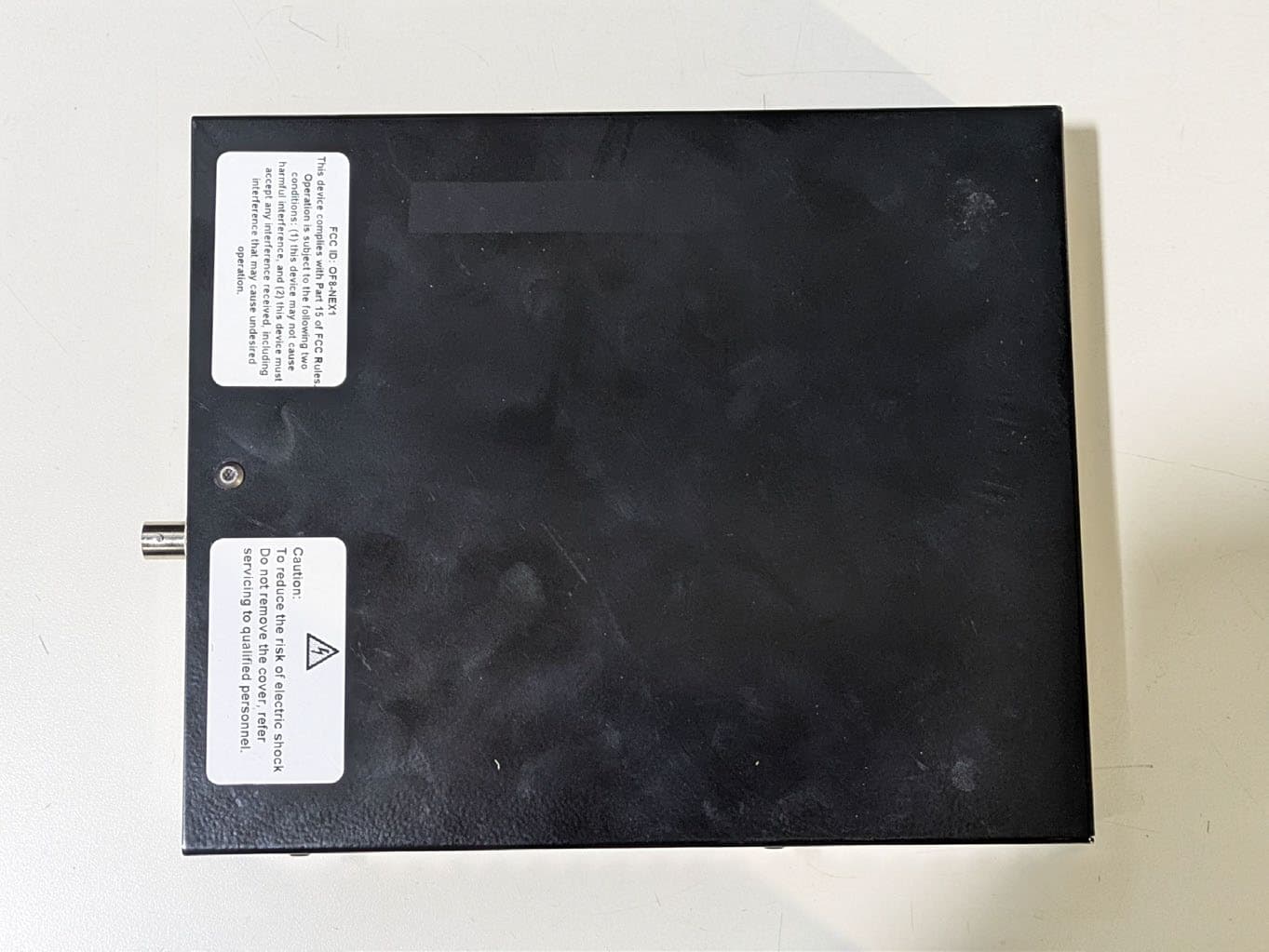
OF8-NEX1
Aug 31, 2026Medical telemetry receiver
Equipment Class
DSS - Part 15 Spread Spectrum Transmitter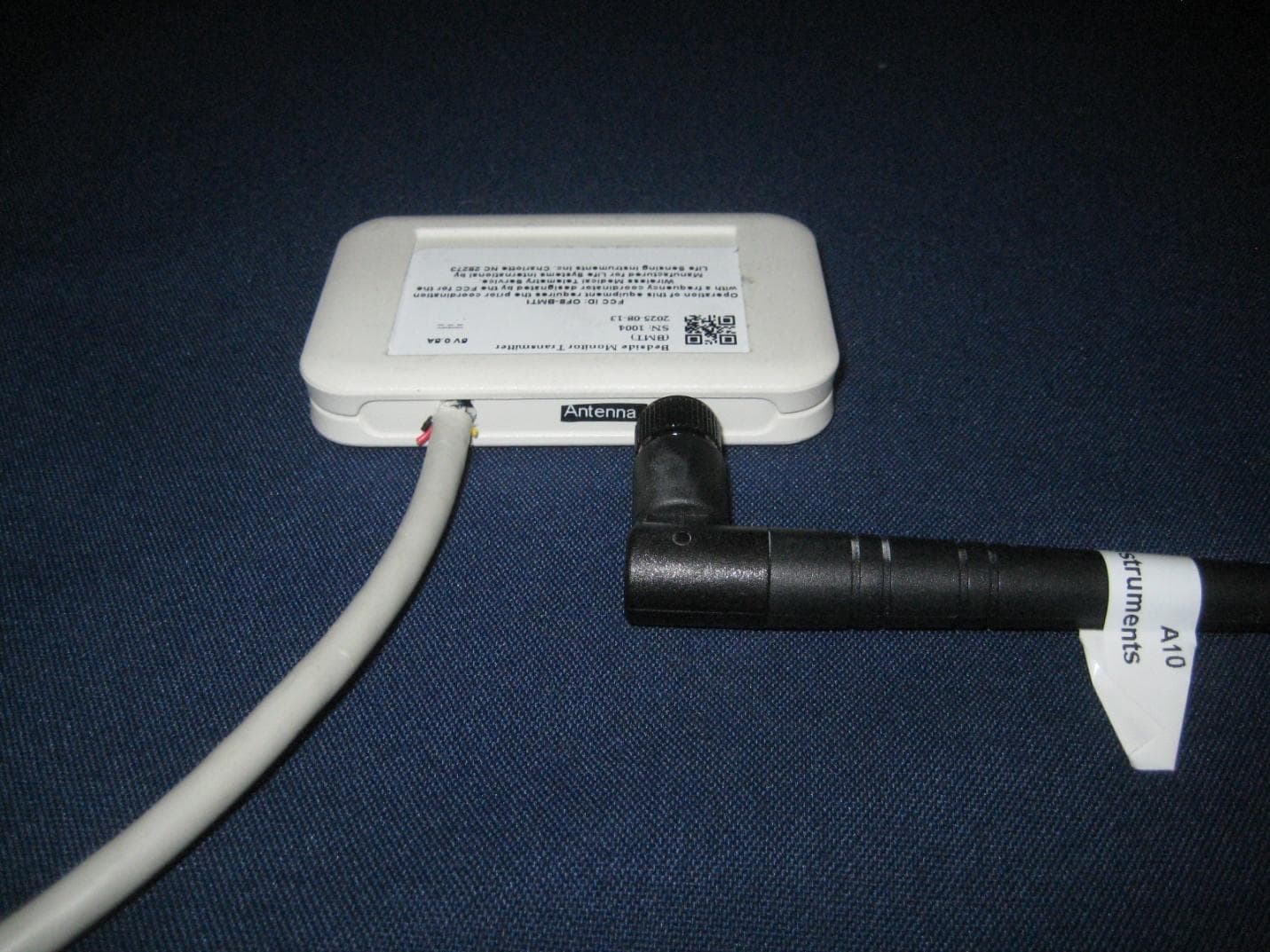
OF8-BMT1
Aug 31, 2026Bedside Wireless Transmitter
Equipment Class
TNB - Licensed Non-Broadcast Station Transmitter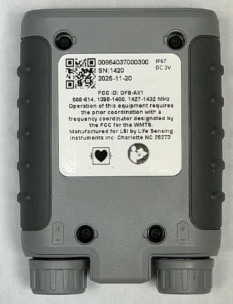
OF8-AX1
Aug 31, 2026Medical telemetry transmitter
Equipment Class
TNB - Licensed Non-Broadcast Station Transmitter
OF8-TM8B
Jan 30, 2003TM8B Dual ECG Transmitter
Equipment Class
TNT - Licensed Non-Broadcast Transmitter Worn on Body